
Related Manuals for ABB Terra 360 CE


Summary of Contents for ABB Terra 360 CE
- Page 1 Operation and installation manual Terra 360/180/60 CE © Copyright ABB. All rights reserved...
- Page 2 Copyright All rights to copyrights, registered trademarks, and trademarks reside with their respective owners. ® Copyright ABB E-mobility B.V.. All rights reserved. 9AKK108467A6398-EN | 002...
-
Page 3: Table Of Contents
Contents Contents About this document................9 Function of this document...................... 9 Disclaimer............................9 Target group..........................9 Revision history..........................9 Language.............................9 Illustrations..........................9 Units of measurement......................10 Typographical conventions....................10 How to use this document.....................10 1.10 General symbols and signal words used in the document..........10 1.11 Manufacturer and contact data.....................11 1.12... - Page 4 Contents 3.3.5 Block diagram - Terra 60 CC and CJ/C..............28 Overview............................30 3.4.1 Overview of the system..................30 3.4.2 Overview of the Terra 60, outside................ 31 3.4.3 Overview of the Terra 60, inside................32 3.4.4 Overview of the Terra 60, air inlet/outlet and filter locations....... 33 3.4.5 Overview of the Terra 180, outside..............34 3.4.6...
- Page 5 Contents Unpacking..........................55 4.2.1 Unpacking procedure..................... 55 4.2.2 Do a check of the transport sensors..............56 Installation..................57 General installation procedure....................57 Site preparation........................57 5.2.1 Prepare the site......................57 5.2.2 Control the space and airflow around the cabinet...........58 Prepare the foundation......................58 5.3.1 Prepare the foundation - general procedure.............
- Page 6 Contents Operation....................79 Prepare before use........................79 Charge session......................... 79 6.2.1 Charge an EV......................79 6.2.2 Start a charge session....................79 6.2.3 Stop a charge session....................80 Energize the EVSE........................80 Remove condensation from the cabinet................81 Local service portal operations.....................81 6.5.1 Start the local service portal.................81 6.5.2 Set the configuration parameters...............
- Page 7 Contents 10.4 Transport specifications......................97 10.5 Required tools for installation....................97 10.6 Required parts for installation....................98 10.7 Torque specifications......................98 10.8 Ambient conditions.........................99 10.9 Tilt sensor specifications.......................99 10.9.1 General specifications................... 99 10.9.2 Wire specifications....................99 10.9.3 Wiring diagram for the tilt sensors..............100 10.10 Cable management system specifications...............101 10.11...
- Page 8 Contents 10.18 Power consumption......................124 10.18.1 General specifications..................124 10.18.2 Terra 360......................... 124 10.18.3 Terra 180......................... 124 10.18.4 Terra 60........................124 10.19 Cooling system specifications.................... 124 10.20 External residual current device specifications...............125 10.20.1 External residual current device (Terra 360)............ 125 10.20.2 External residual current device (Terra 180)............
-
Page 9: About This Document
EVSE. Disclaimer ABB E-mobility B.V. shall not be liable for any damages, losses, costs or expenses resulting from the improper handling of the EVSE, in particular resulting from non- compliance with the instructions of this document and other applicable regulations and standards (e.g. -
Page 10: Units Of Measurement
About this document Units of measurement SI units of measurement (metric system) are used. If necessary, the document shows other units between parentheses () or in separate columns in tables. Typographical conventions The lists and steps in procedures have numbers (123) or letters (abc) if the sequence is important. -
Page 11: Manufacturer And Contact Data
Electrotechnical expertise is required, according to the local rules. Alternating current supply Note: It is possible that not all symbols or signal words are present in this document. 1.11 Manufacturer and contact data Manufacturer ABB E-mobility B.V. Heertjeslaan 6 2629 JG Delft The Netherlands 9AKK108467A6398-EN | 002... -
Page 12: Abbreviations
About this document Contact data ABB E-mobility B.V. in your country can give you support on the EVSE. You can find the contact data here: https://new.abb.com/ev-charging 1.12 Abbreviations Abbreviation Definition Alternating current BESS Battery energy storage system Controller area network... -
Page 13: Orientation Agreements
About this document Term Definition Local rules All rules that apply to the EVSE during the entire lifecy- cle of the EVSE. The local rules also include the national laws and regulations Open charge point proto- Open standard for communication with charge sta- tions Owner Legal owner of the EVSE... -
Page 14: Safety
Improper operation (in breach of the technical requirements or specifications or manuals of the product), negligence or repairs carried out by the Owner (or any third party not authorized by ABB). • Non-compliance with the applicable safety regulations or other legal standards by other parties than ABB. -
Page 15: Responsibilities For The Owner
Safety Responsibilities for the owner The owner is the person who runs the EVSE for commercial or business purposes for itself or leaves it to a third party for use. During operation the owner bears legal responsibility for the protection of the user, other employees or third parties, which includes the following: •... -
Page 16: Personal Protective Equipment
Safety Personal protective equipment Symbol Description Protective clothing Safety gloves Safety shoes Safety glasses Safety instructions during transport Preliminary requirements • Installation engineer • • Make sure that the hoisting equipment or forklift truck can lift the EVSE safely. Take into account the mass and the center of gravity of the EVSE. •... -
Page 17: Safety Instructions For Use
Safety • Make sure that there is no voltage on the AC input cables during the complete installation procedure. • Keep unqualified personnel at a safe distance during installation. • Only use electrical wires of sufficient gauge and insulation to handle the rated current and voltage demand. -
Page 18: Signs On The Evse
Safety conductors and connected to the equipment grounding terminal or lead on the product. • Make sure that the connections to the EVSE comply with all applicable local rules. 2.11 Signs on the EVSE Symbol Description General risk Hazardous voltage that gives risk of electrocution Risk of pinching or crushing of body parts Rotating parts that can cause a risk of entrapment Hot surface that gives risk of burn injuries... -
Page 19: Cyber Security
The manufacturer (ABB E-mobility B.V.) and its affiliates are not liable for damages and/or losses related to such security breaches, any unauthorized access, interference, intrusion, leakage and/or theft of data or information. -
Page 20: Description
2629 JG Delft, IP54 VDE - XXXXxxxx XX-XXXXX x Class X xxx. xx The Nederlands XX-XXXXX x MADE IN ITALY www.abb.com Manufacturer EVSE rating Serial number Address of the manufacturer Part number of the EVSE CE mark Production date Barcode with the serial number of... - Page 21 Description Danger: General risk • If you use the EVSE in any other way than described in the related documents, you can cause death, injury and damage. • Use the EVSE only as intended. 9AKK108467A6398-EN | 002...
-
Page 22: Working Principles
Description Working principles 3.3.1 Block diagram - Terra 360 9AKK108467A6398-EN | 002... - Page 23 Description Fused manual switch Power bridge Auxiliary fuse switch Power module Auxiliary residual-current device EMC filter AC surge-protection device Auxiliary transformer LED strip power supply Overcurrent protection device Auxiliary power supply DC contactor Power supply for the cooling unit Shunt current (liquid cooled cables) Charge protocol interface Heater...
-
Page 24: Terra 360 - 2 Outlets, 25 Percent
Description 3.3.2 Terra 360 - 2 outlets, 25 percent AC MC1 LD Fused manual switch Charge protocol interface Interlink contactor Cabinet controller board AC contactor Touchscreen Power bridge Charge cable Power module Upstream Leakage detect DC contactor MC1 Upstream magnetic circuit breaker Colours Description Control bus... -
Page 25: Terra 360 - 2 Outlets, 50 Percent
Description 3.3.3 Terra 360 - 2 outlets, 50 percent AC MC1 LD Fused manual switch Charge protocol interface Interlink contactor Cabinet controller board AC contactor Touchscreen Power bridge Charge cable Power module Upstream Leakage detect DC contactor MC1 Upstream magnetic circuit breaker Colours Description Control bus... -
Page 26: Block Diagram - Terra 180
Description 3.3.4 Block diagram - Terra 180 9AKK108467A6398-EN | 002... - Page 27 Description Fused manual switch Power bridge Auxiliary fuse switch Power module Auxiliary residual-current device EMC filter AC surge-protection device Auxiliary transformer LED strip power supply Overcurrent protection device Auxiliary power supply DC contactor Power supply for the cooling unit Shunt current (liquid cooled cables) Charge protocol interface Heater...
-
Page 28: Block Diagram - Terra 60 Cc And Cj/C
Description 3.3.5 Block diagram - Terra 60 CC and CJ/C 9AKK108467A6398-EN | 002... - Page 29 Description Fused manual switch Auxiliary transformer RFID Overcurrent protection device Auxiliary residual-current device DC contactor AC surge-protection device Shunt current LED strip power supply DC charge protocol interface Auxiliary power supply Insulation monitor interface Heater Meter reading unit LED strip Cabinet controller board DC fuse Touchscreen display...
-
Page 30: Overview
Description Overview 3.4.1 Overview of the system AC input cable Parking space Power distribution board Front of the EVSE EV charge cable EVSE Part Function The EV of which the batteries need to be charged EVSE Refer to section 3.4.2. Parking space Location for the EV during the charge session AC input cable... -
Page 31: Overview Of The Terra 60, Outside
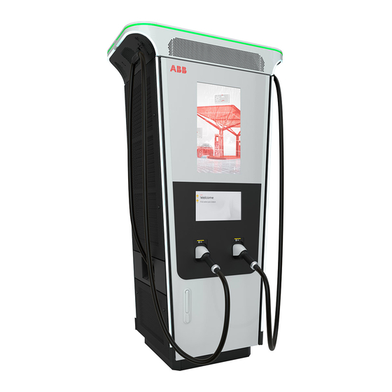
Description 3.4.2 Overview of the Terra 60, outside Removable base Meter display Bottom left door Payment terminal Type plate Type 2 socket Top left door EV charge cable with fuel label Cable management system (CMS) EN17186 marking Antenna Front door Advertisement screen Bottom right door Touchscreen... -
Page 32: Overview Of The Terra 60, Inside
Description 3.4.3 Overview of the Terra 60, inside Power modules MID Meters for MRU Acoustic baffle Core control board Cable gland plate CPI outlet 1 and 2 PE busbar Power bridge Main AC switch Fuse, CT and surge protection for Auxiliary power supply breaker DC outlet 2 AC surge protection device... -
Page 33: Overview Of The Terra 60, Air Inlet/Outlet And Filter Locations
Description Part Function Fuse, CT and Surge Protection for DC To provide current readings and surge Outlet 1 & 2 protection DC outlet 1 and 2 To provide DC output power AC relay To connect or disconnect a power mod- ules group (from 1 to 4) 3.4.4 Overview of the Terra 60, air inlet/outlet and filter locations... -
Page 34: Overview Of The Terra 180, Outside
Description 3.4.5 Overview of the Terra 180, outside Removable base Meter display Bottom left door Payment terminal Type plate EV charge cable with fuel label Top left door EN17186 marking Cable management system (CMS) Front door Antenna Bottom right door Advertisement screen Rear door Touchscreen... -
Page 35: Overview Of The Evse, Inside
Description 3.4.6 Overview of the Terra 180, inside Power modules MID Meters for MRU Acoustic baffle Core control board Cable gland plate CPI outlet 1 and 2 PE busbar Fuse, CT and surge protection for Main AC switch DC outlet 2 Auxiliary power supply breaker Fuse, CT and surge protection for AC surge protection device... -
Page 36: Overview Of The Terra 180, Air Inlet/Outlet And Filter Locations
Description Part Function Fuse, CT and Surge Protection for DC To provide current readings and surge Outlet 1 & 2 protection DC outlet 1 and 2 To provide DC output power Cooling fan To control the internal temperature AC relay To connect or disconnect a power mod- ules group (from 1 to 4) 3.4.7... -
Page 37: Overview Of The Terra 360, Outside
Description 3.4.8 Overview of the Terra 360, outside Removable base Meter display Bottom left door Payment terminal Type plate EV charge cable with fuel label Top left door EN17186 marking Cable management system (CMS) Front door Antenna Bottom right door Advertisement screen Rear door Touchscreen... -
Page 38: Overview Of The Terra 360, Inside
Description 3.4.9 Overview of the Terra 360, inside 7 10 1 8 11 2 9 12 3 Power modules MID Meters for MRU Acoustic baffle Core control board Cable gland plate CPI outlet 1 and 2 PE busbar Power bridge Main AC switch Fuse, CT and surge protection for Auxiliary power supply breaker... -
Page 39: Overview Of The Terra 360, Air Inlet/Outlet And Filter Locations
Description Part Function Fuse, CT and Surge Protection for DC To provide current readings and surge Outlet 1 & 2 protection DC outlet 1 and 2 To provide DC output power Cooling fan To control the internal temperature AC relay To connect or disconnect a power mod- ules group (from 1 to 4) 3.4.10... -
Page 40: Overview Of The Cable Management System
Description 3.4.11 Overview of the cable management system Cable clamp Gland Wheel 3.4.12 Overview of the locations of the lifting points Preseries Eye bolt 9AKK108467A6398-EN | 002... -
Page 41: Authorization To Charge
OCPP. Payment terminal The touchscreen guides the user how to use the payment terminal. Note: • To use and adjust the settings of the payment terminal, you require the ABB Payment Web tool. 9AKK108467A6398-EN | 002... -
Page 42: Options
Description Options 3.7.1 EV charge cable, CCS 1 The manufacturer can deliver the EVSE with CCS 1 connectors on the EV charge cables. For the current rating specifications, refer to section 10.2. For the cable length specifications, refer to section 10.11. 3.7.2 EV charge cable, CCS 2 The manufacturer can deliver the EVSE with CCS 2 connectors on the EV charge... -
Page 43: Socket, Type 2
Description 3.7.3 Socket, Type 2 3.7.4 EV charge cable, CHAdeMO The manufacturer can deliver the EVSE with CHAdeMO connectors on the EV charge cables. For the current rating specifications, refer to section 10.2. For the cable length specifications, refer to section 10.11. 3.7.5 Integrated payment terminal The manufacturer can deliver the EVSE with different payment terminals. -
Page 44: Integrated Payment Terminal - Nayax
Description 3.7.6 Integrated payment terminal - Nayax 3.7.7 Integrated payment terminal - CCV 3.7.8 Fiscal metering system The EVSE can optionally be equipped with an MID compliant DC energy meter. This upgrade can be installed in the factory or in the field. Time (hh:mm:ss) Delivered DC power (kWh) Date (YY-MM-DD) -
Page 45: Tilt Sensors
The illustration shows the tilt sensors interface with the power distribution system of the site. Please note that the shown branch circuit breaker, 24 V DC supply delivered from an UPS, and all other components are not within the scope of ABB E-Mobility, therefore are not provided in the EVSE. -
Page 46: Cable Management System
Description ) The breaker will trip in the event of loss of voltage to the undervoltage release (I) It is possible to install tilt sensors afterwards. Ask ABB E-mobility B.V.. Refer to section 1.11. Cable management system The EVSE has a cable management system, that retracts the cables and holds the cables in position when the EVSE is not in use. -
Page 47: Concurrent Allocation
Description Note: EV charging with the use of the CCS standard can 'fall asleep' if the EVSE does not start the session within a few minutes. This is a common issue. It is recommended to connect a second EV only shortly before the first charge session ends. -
Page 48: Dynamic Allocation 'Fair Share
Description Note: This feature is available from SW update 1.8. 3.9.4 Dynamic allocation 'Fair share' 0 - 50% 0 - 50% 50 - 100% 50 - 100% 51 - 99% 51 - 99% Situation when the battery level of an EV is below 50 percent: •... -
Page 49: Description Of The Touchscreen
Description The amplitude of the current peaks can change. These factors are the source of the differences: • The location of the EVSE • The power grid • The earth impedance References: • For the general input specifications, refer to section 10.15.1 •... -
Page 50: General Description Of The Buttons
Description 3.11.2 General description of the buttons Button Name Description To select the CCS connector CHAdeMo To select the CHAdeMo connector Language To change the language on the touchscreen. The button shows the code of the selected language. Start To start the charge session start Stop To stop the charge session... -
Page 51: Status Of The Evse Leds
Description 3.12 Status of the EVSE LEDs LEDs Description The EVSE is in idle mode and ready for use: • The top LEDs of the EVSE are green One charge session starts: • The side LEDs of the selected outlet change to blue •... -
Page 52: Cloud Service Portal
To set the OCPP parameters, refer to section 6.5.3 3.14 Cloud service portal ABB E-mobility B.V. provides a set of cloud-based tools to commission, monitor and troubleshoot the EVSE. Please refer to the manufacturer's e-Mobility representative for more information. 9AKK108467A6398-EN | 002... -
Page 53: Transport, Handling And Unpacking
EV Charger and keep sufficient distance away from moving EV Charger. ABB is not liable for any damages resulting from the improper handling and transportation of the Electrical Vehicle Charger, in particular resulting from non- compliance with these instructions and other applicable regualtions and standards (e.g. -
Page 54: Move The Packaged Cabinet With A Forklift Truck
Transport, handling and unpacking Warning: Risk of pinching or crushing, the cabinet is heavy • Make sure that the hoisting equipment can lift the cabinet safely. • Obey the safety instructions that apply to the hoisting equipment. • Take into account the dimensions, the mass and the center of gravity of the EVSE. -
Page 55: Unpacking
Transport, handling and unpacking Procedure 1. Move the forks of the forklift truck in the gaps at the side of the cabinet. 2. Move the cabinet to the correct location. Unpacking 4.2.1 Unpacking procedure Preliminary requirements • Installation engineer 9AKK108467A6398-EN | 002... -
Page 56: Do A Check Of The Transport Sensors
Transport, handling and unpacking Procedure 1. Do a check on the transport sensors. 2. Remove the packaging material. To discard the packaging material, refer to section 2.12. 3. Make sure that all parts are delivered according to the order. Refer to the order and section 10.3. -
Page 57: Installation
Installation Installation General installation procedure Preliminary requirements • All required permits to • Tools for installation. Refer agree with the local rules, to section 10.5. are granted. • The AC input cable is available. • Installation engineer • There is no voltage on the AC input cable during the complete installation procedure. -
Page 58: Control The Space And Airflow Around The Cabinet
Installation 4. Prepare the cables: • AC input cable. Refer to section 10.15. • PE wire. The diameter depends on the length, method of installation and other factors. Make sure that the PE wire is in accordance with the safety instructions. -
Page 59: Prepare A Standard Prefabricated Foundation
Installation 5.3.2 Prepare a standard prefabricated foundation Preliminary requirements • Installation engineer • Prefabricated foundation. Refer to section 10.11.8. Procedure 1. Make the foundation (A). Do one of these steps: • Contact the manufacturer to order the foundation for your EVSE. Refer to section 1.11. -
Page 60: Detach The Cabinet (Terra 180 And 60)
Installation Procedure 1. Open the front door and the rear door of the EVSE. Refer to section 8.1. 2. Remove these parts: • The lexan insulators (A) and (B) • The metal protection (C). To remove the metal protection, it is necessary to open the lower door on the left side also. -
Page 61: Detach The Base
Installation Procedure Terra 60 Terra 180 1. Open the front door and the rear door of the EVSE. Refer to section 8.1. 2. Remove these parts: • The lexan protection on the AC section (A). • The lexan protection under the main AC switch (B). 3. -
Page 62: Prepare The Cables
Installation Procedure 1. Remove the 4 screws from the base covers (A). 2. Remove the base covers. 3. Remove the 6 fasteners (B) that attach the base (C) to the pallet. 4. Remove the base from the pallet. Prepare the cables 5.5.1 Cable installation procedure Preliminary requirements... -
Page 63: Open The Cable Glands (Terra 60 And 180)
Installation Procedure 1. Open the necessary cable glands for these cables: • AC input cables L1, L2 and L3 (A). (27–35 mm / 1.06–1.38 in) • Ethernet / signals cables (B). (19–28 mm / 0.75–1.10 in) • Protective Earth (PE) cables (C). (27–35 mm / 1.06–1.38 in) •... -
Page 64: Install The Base On The Foundation
Installation Procedure 1. Put the cables L1, L2, L3 and PE through the cable guide plate. If there is a Neutral cable, then also put it through the cable guide plate. Apply the full cable slack (350mm / 20 in). 2. -
Page 65: Mechanical Installation
Installation Procedure 1. Cut the cables (B) to the correct length (X) that is the distance between the cable gland plate (C) and the center of thet connection terminal (A) on the main switch (D). For the specifications, refer to section 10.15.2. For Terra 360: (X) is 210 mm (8.27 in) for the cables L1, L2 and L3. -
Page 66: Connect The Cabinet To The Base
Installation Procedure 1. Move the cabinet (A) on top of the base (B). Use a crane or a forklift. 2. Carefully lower the cabinet on the base. Make sure that cables do not get trapped between the cabinet and the base. -
Page 67: Connect The Wires Of The Ac Input Cable (Terra 360)
Installation Procedure 1. Open the front door. Refer to section 8.1. 2. Connect the parts that follow: • The wires of the AC input cable and neutral. • For Terra 360, refer to section 5.7.2 • For Terra 180 and 60, refer to section 5.7.3. •... -
Page 68: Connect The Wires Of The Ac Input Cable (Terra 180)
Installation Procedure 1. Prepare the wires. a. Cut the wires (A), (B) and (C) to the length that is sufficient for connection to the connector on the manual switch (D). b. Attach the cable lugs (E) to the end of the wires. Use the crimp plier tool. 2. -
Page 69: Connect The Wires Of The Ac Input Cable (Terra 60)
Installation • Wire stripper pliers • Wire cutter • Crimp plier tool • Torque socket wrench Procedure 1. Prepare the wires. a. Cut the wires (A) to (D) to the length that is sufficient for connection to the connectors on the manual switch (E). b. - Page 70 Installation • • Installation engineer • Wire stripper pliers • Wire cutter • Crimp plier tool • Torque socket wrench Procedure 1. Prepare the wires. a. Cut the wires (A) to (D) to the length that is sufficient for connection to the connectors on the manual switch (E).
-
Page 71: Connect The Pe Wire (Terra 360)
Installation 5.7.5 Connect the PE wire (Terra 360) Preliminary requirements • The front and right doors • Cable lug M11 are open. • Fasteners M11 • • Installation engineer • Make sure that the earthing connection is in accordance with the standard IEC 60364-5-54. -
Page 72: Connect The Pe Wire (Terra 180 And 60)
Installation 5.7.6 Connect the PE wire (Terra 180 and 60) Preliminary requirements • The front and right doors • Cable lug M11 are open. • Fasteners M11 • • Installation engineer • Make sure that the earthing connection is in accordance with the standard IEC 60364-5-54. -
Page 73: Connect The Ethernet Cable (Terra 360)
Installation 5.7.7 Connect the Ethernet cable (Terra 360) Preliminary requirements • The front door is open. • Installation engineer Procedure 1. Connect the Ethernet connector (A) to the Ethernet cable (B). The Ethernet cable connection is in location (C) inside the EVSE. 5.7.8 Connect the Ethernet cable (Terra 180) Preliminary requirements... -
Page 74: Connect The Ethernet Cable (Terra 180)
Installation Procedure 1. Connect the Ethernet connector (A) to the Ethernet cable (B). The Ethernet cable connection is in location (C) inside the EVSE. 5.7.9 Connect the Ethernet cable (Terra 180) Preliminary requirements • The front door is open. • Installation engineer 9AKK108467A6398-EN | 002... -
Page 75: Tilt Sensors Installation (Option)
Installation Procedure 1. Connect the Ethernet connector (A) to the Ethernet cable (B). The Ethernet cable connection is in location (C) inside the EVSE. Tilt sensors installation (option) 5.8.1 General procedure For all specifications of the tilt sensors, refer to section 10.9. 1. -
Page 76: Install The Bracket Of The Tilt Sensors
Installation 5.8.2 Install the bracket of the tilt sensors Preliminary requirements • Installation engineer • Tilt sensor lugged • Bracket • Alternative bracket • Screwdriver 3.5 mm • Cross screwdriver size 2 Procedure 1. Install the tilt switch (A) on the bracket (B). -
Page 77: Connect The Tilt Sensors
Installation 5.8.4 Connect the tilt sensors Preliminary requirements • Installation engineer • Torque screw driver • Wire cutter • Wire stripper pliers • Crimp pliers • For the specifications of the wires and the strip length, refer to section 10.9.2. •... - Page 78 Installation Procedure 1. Tell the owner that the EVSE is ready for commissioning. 2. Make sure that the site is in accordance with these requirements: • The EVSE is installed. • AC input power is available from the grid provider. •...
-
Page 79: Operation
Operation Operation Prepare before use Preliminary requirements • Owner Procedure 1. Appoint a site operator and an installation engineer, if these are other persons than you. 2. Make sure that the EVSE is installed according to the instructions in chapter 5. 3. -
Page 80: Stop A Charge Session
Operation Procedure 1. On the touchscreen, select the applicable connector button. Note: If you skip this step, the EVSE selects the correct connector automatically when you connect the EV charge cable to the EV. 2. Remove the EV charge cable from the EVSE. 3. -
Page 81: Remove Condensation From The Cabinet
Operation Procedure 1. Open the front door. Refer to section 8.1. 1 position (vertical). 2. Set the manual switch to the Warning: General hazard • Be careful and use both your hands to turn the manual switch. You need some force to turn the switch. 3. -
Page 82: Set The Configuration Parameters
Operation Procedure 1. Open the front door of the EVSE. Refer to section 8.1. The HMI starts the local service portal application. The outside HMI goes into idle mode. On the inside HMI, the authorization screen shows. 2. Enter the pin code. The PIN code is an alphanumeric code "1234WWYYSSS". -
Page 83: Close The Local Service Portal
Operation 6.5.5 Close the local service portal Exit . 1. On the touchscreen, select Confirm in the dialog box. 2. Select The HMI will switch to the user application. After 5 minutes of touch inactivity on the screen, the local service portal will close. The HMI will switch to the regular EVSE application. -
Page 84: Maintenance And Cleaning
Maintenance and cleaning Maintenance and cleaning Maintenance schedule for the owner Task Frequency Procedure Clean the cabinet. 4 months Refer to section 7.2. Do a check for damage on 3 months Refer to section 7.3. the EV charge cables and the connectors. -
Page 85: Do A Check On The Cabinet
Maintenance and cleaning Do a check on the cabinet Preliminary requirements • Owner Procedure 1. Do a check for damage on these parts: Part Damage EV charge cables and connectors Cracks or ruptures Internal wires of the cable are visible Touchscreen Cracks Touch screen does not work... - Page 86 Maintenance and cleaning Procedure 1. Get access to the air filter. a. For air filters type A and B, open the door. Refer to section 8.1. b. For air filter type C, remove the top cover of the EVSE. 2. Loosen the fasteners of the air filter cover. Use the spanner. 3.
-
Page 87: Energize The Evse
Maintenance and cleaning De-energize the EVSE 7.5.1 De-energize the EVSE - general procedure Preliminary requirements • • Voltage tester Procedure 1. Open the front door and right doors. Refer to section 8.1. 0 position (horizontal). 2. Set the manual switch to the Warning: General hazard •... -
Page 88: Measure The Ac Voltage (Terra 180)
Maintenance and cleaning Procedure 1. Measure the AC voltage between the terminals on the surge protection device switch: L1 , L2 , L3 to N • L1 to L2 • L1 to L3 • L2 to L3 • Use the voltage tester. L1 , L2 , L3 Note: The surge protection device switch shows the indications L1 , L2 , L3 to ground. -
Page 89: Measure The Dc Voltage
Maintenance and cleaning Procedure 1. Measure the AC voltage between the terminals on the surge protection device switch: L1 , L2 , L3 to N • L1 to L2 • L1 to L3 • L2 to L3 • Use the voltage tester. L1 , L2 , L3 Note: The surge protection device switch shows the indications 7.5.5... -
Page 90: Access To Parts
Access to parts Access to parts Open the doors Preliminary requirements • • Door key Danger: Hazardous voltage • Make sure that only qualified persons have access to the door key. Note: There is one unique door key for each cabinet. Procedure 1. -
Page 91: Install The Border Covers
Access to parts Procedure 1. Close the front door (A): a. Close the front door (A). b. Lock the lock of the front door (B). Use the door key. 2. Close the left or right door panels (C): a. Close the door panel. b. - Page 92 Access to parts Procedure 1. Remove these parts: 1. Fasteners (A) 2. Border covers (B) 9AKK108467A6398-EN | 002...
-
Page 93: Troubleshooting
Troubleshooting Troubleshooting Troubleshooting procedure 1. Try to find a solution for the problem with the aid of the information in this document. 2. If you cannot find a solution for the problem, contact your local representative of the manufacturer. Refer to section 1.11. Troubleshooting table Problem Possible cause... -
Page 94: Technical Data
Technical data Technical data 10.1 EVSE type The EVSE type is a code. The code has 7 parts: P - Q - R - S - T - U - V - that can have multiple values. Code parts Sub- Section Value Meaning of the value... - Page 95 Technical data Code parts Sub- Section Value Meaning of the value code S: Cable fea- Cable length tures Cable type Non liquid cooled Liquid cooled Cable rating 125 A 200 A 400 A 500 A Additional ca- Connector detection in the con- ble features nector holder Cable/retraction management...
- Page 96 Technical data Code parts Sub- Section Value Meaning of the value code Double modem (one modem is the default) MID compliant energy output metering Remote-resettable RCD for AC output; needs Helios/backdoor command (18Q1) Tilt sensor High current capable, for Terra xx4 (up to 400 A in cabinet 1.1, instead of 200 A in cabinet 1.0) V: Customized design...
-
Page 97: General Specifications
Technical data 10.2 General specifications Parameter Specification Compliance and safety CHAdeMO 1.2 EN17186 IP rating The type plate shows the specification. Refer to section 3.1. IK rating according to IEC 62262: enclo- IK10 sure IK rating according to IEC 62262: IK08 touchscreen EMC rating... -
Page 98: Required Parts For Installation
Technical data Parameter Specification Torque socket wrench 5 to 20 Nm, size M8 (13 mm) and M6 (10 Ratchet spanner with socket and exten- Size: M5 (8 mm) and M6 (10 mm) sion Tie-wraps Standard Voltage tester To switch 200 mA of test current (exam- ple: Duspol) Digital multimeter Standard... -
Page 99: Ambient Conditions
Technical data 10.8 Ambient conditions Parameter Specification Environment, general Indoor and outdoor Storage temperature -40 °C to +70 °C Temperature during use -35 °C to +55 °C Maximum altitude above sea level 2500 m Temperature derating 40 °C 10.9 Tilt sensor specifications 10.9.1 General specifications Parameter... -
Page 100: Wiring Diagram For The Tilt Sensors
Technical data 10.9.3 Wiring diagram for the tilt sensors 24 Vdc 0 Vdc EVSE Upstream breaker in the power Twisted wire distribution board External power supply Scope of supply by the manufacturer Parameter Specification Signal description TB label White cable 24 V DC Yellow cable 0 V DC... -
Page 101: Cable Management System Specifications
6AGC106063 CCS2 6AGC106063 ChaDeMo 6AGC106063 CCS2 6AGC106068 CCS2 Liquid 6AGC106068 The maximum cable length supported by the ABB cable retraction system is 6 m (20 ft). 10.11 Dimensions 10.11.1 General dimensions (Terra 360) Parameter Specification [mm] [in] Width of the cabinet (X-dimension) -
Page 102: General Dimensions (Terra 180 And 60)
Technical data Parameter Specification [ft] Length of the EV charge cable (air- cooled) for CCS 1, CCS 2 and CHAdeMO Length of the EV charge cable (liquid- cooled) for CCS 1 and CCS 2 10.11.2 General dimensions (Terra 180 and 60) Parameter Specification [mm]... -
Page 103: Mass Of The Evse (Without Packaging Material)
Technical data Parameter Specification [metric] [imperial] Mass of a wooden crate packaged EVSE EVSE weight + 75 EVSE weight + 165 Maximum tipping angle 15° 15° 10.11.4 Mass of the EVSE (without packaging material) Parameter Specification [kg] [lbs] Terra 360 1870 Terra 180 1391... -
Page 104: Floor Space Requirements (Terra 360, Serial Production)
Technical data Parameter Specification [mm] [mm] [in] Note: These dimensions only refer to the required space for the cabinet. A minimum of 1 m extra on each side is required to allow operations on the EVSE. 10.11.6 Floor space requirements (Terra 360, serial production) Cabinet Space to open the rear door Space to open the left side door... -
Page 105: Floor Space Requirements (Terra 180 And 60)
Technical data 10.11.7 Floor space requirements (Terra 180 and 60) Cabinet Space to open the rear door Space to open the left door Space to open the front door Space to open the right door Parameter Specification [mm] [in] 1000 1000 Note: These dimensions only refer to the required space for the cabinet. -
Page 106: Prefabricated Foundation (Terra 360)
Technical data 10.11.8 Prefabricated foundation (Terra 360) Foundation Width of the hole Hole for the foundation Depth of the hole Width of the foundation Height of the hole Depth of the foundation Distance of the foundation above Height of the foundation the ground level Parameter Specification Terra 60 / 180... -
Page 107: Cast Foundation (Terra 360)
Technical data 10.11.9 Cast foundation (Terra 360) Holes to install the fasteners of the Cable arrival area EVSE Parameter Specification [mm] [mm] [in] M12, depth 70 M12, depth 3 245 x 330 9.6 x 13 19.9 16.9 41.8 9AKK108467A6398-EN | 002... -
Page 108: Cast Foundation (Terra 180 And 60)
Technical data 10.11.10 Cast foundation (Terra 180 and 60) Holes to install the fasteners of the Cable arrival area EVSE Parameter Specification [mm] [mm] [in] M12, depth 70 M12, depth 3 245 x 330 9.6 x 13 19.9 12.6 10.11.11 Cable slack Parameter Specification... -
Page 109: Height Of User Operable Elements
Technical data 10.11.12 Height of user operable elements Ground level EVSE lowest user operable element Maximum height of the user EVSE base operable elements according to Curb Lowest height of the user operable elements according to ADA EVSE highest user operable element Parameter Specification... -
Page 110: Communication Interface Specifications
Technical data Make sure that the installed EVSE complies with ADA requirements. The distance from the base of the EVSE to the minimum and maximum height of the user operable elements must be accordance with the ADA recommendations. Note: It is the responsibility of the installer to make sure that the EVSE complies with ADA requirements. -
Page 111: Evse Rating In Heavy Duty Operation
Technical data Parameter Specification Example of power out- Ambient temperature Power Out- De-rating Peak dura- put for Ter- put (see tion ra 360-12PM normal duty rating) [°C] [°F] [min] [kW] - 35 … + 20 -31 … + 68 > 30 360 (peak) + 21 …... -
Page 112: Evse Derating During Heavy Duty Operation
Technical data Parameter Specification Model Installed power Rated power [kW] Terra 360 6 power modules (180) Terra 360 8 power modules (240) Terra 360 12 power modules (360) 10.13.4 EVSE derating during heavy duty operation Normal duty operation applies for use in public applications with moderate traffic. Parameter Specification Example of... - Page 113 Technical data Working point Electric load VTHD (L1/L2/L3) ITHD (L1/L2/L3) 400 V - 300 A 100 % 2.26 % - 2.33 % - 3.73 % - 3.56 % - 2.50 % 4.00 % Order Phase L1 Phase L2 Phase L3 I rms I rms I rms...
-
Page 114: Terra 180, Equal Share
Technical data Working point Electric load VTHD (L1/L2/L3) ITHD (L1/L2/L3) 400 V - 300 A 100 % 2.26 % - 2.33 % - 3.73 % - 3.56 % - 2.50 % 4.00 % Order Phase L1 Phase L2 Phase L3 I rms I rms I rms... - Page 115 Technical data Working point Electric load VTHD (L1/L2/L3) ITHD (L1/L2/L3) 400 V - 200 A 100 % 0.47 % - 0.46 % - 4.29 % - 3.92 % - 0.48 % 4.23 % Order Phase L1 Phase L2 Phase L3 I rms I rms I rms...
-
Page 116: Harmonics Terra 60
Technical data Working point Electric load VTHD (L1/L2/L3) ITHD (L1/L2/L3) 400 V - 200 A 100 % 0.47 % - 0.46 % - 4.29 % - 3.92 % - 0.48 % 4.23 % Order Phase L1 Phase L2 Phase L3 I rms I rms I rms... -
Page 117: Ac Input Specifications
Technical data Working point Electric load VTHD (L1/L2/L3) ITHD (L1/L2/L3) 400 V - 150 A 100 % 2.00 % - 2.53 % - 4.01 % - 4.37 % - 2.36 % 4.25 % Order Phase L1 Phase L2 Phase L3 I rms I rms I rms... -
Page 118: Ac Input Cable
Technical data Parameter Specification TN-C-S TT (with upstream RCD) Input voltage range 400 VAC +/- 10% (50 Hz or 60 Hz) Power factor at full load > 0.96 Efficiency > 95% at nominal output power Total harmonic distortion (current) < 4.5% 10.15.2 AC input cable Parameter... -
Page 119: Terra 60
Technical data 10.15.5 Terra 60 Parameter Specification [A] Maximum rated input current Maximum rated input current with AC socket 10.16 DC output specifications 10.16.1 General specifications Parameter Specification DC output voltage range, CCS 200-920 V DC DC output voltage range, CHAdeMO 150-500 V DC (In Japan 150-450 V DC) Minimum DC output current... - Page 120 Technical data Output current in function of output voltage 300A 500A Output current [A] Output voltage [V] Output power in function of output voltage 300A 500A Output power [kW] Output voltage [V] 9AKK108467A6398-EN | 002...
-
Page 121: Terra 360
Technical data 10.16.3 Terra 180 Parameter Specification DC output power, mode 1, continuously Maximum 180 kW on one EV charge cable DC output power, mode 2, continuously Maximum 90 kW on two EV charge cables Simultaneous DC on two outlets Yes. -
Page 122: Terra 180
Technical data Output power in function of output voltage 300A 500A Output power [kW] Output voltage [V] 10.16.4 Terra 60 Parameter Specification DC output power, mode 1, continuously Maximum 60 kW on one EV charge cable DC output power, mode 2, continuously Maximum 30 kW on two EV charge cables Simultaneous DC on two outlets... - Page 123 Technical data Output current in function of output voltage 150A Output current [A] Output voltage [V] Output power in function of output voltage 150A Output power [kW] Output voltage [V] 9AKK108467A6398-EN | 002...
-
Page 124: Terra 60
Terra 180 Parameter Specification [kVA) Power consumption (normal operation) 10.18.4 Terra 60 Parameter Specification [kVA) Power consumption (normal operation) 10.19 Cooling system specifications Parameter Specification System Controls ABB cooling system controller with full control and full diagnostics 9AKK108467A6398-EN | 002... -
Page 125: External Residual Current Device Specifications
Technical data Parameter Specification Cooling fluid Huber+Suhner CP3-002 • Readily biodegradable, aligns with OECD criteria • German Water Hazard Class 1 (slight- ly hazardous to water) • No indication of bioaccumulation po- tential • Low mobility in soil Fluid couplers Screw-type connectors Spill containment Tank integrated in side panel on the LED... -
Page 126: External Residual Current Device (Terra 180)
Technical data Parameter Function or specification MV switch Dedicated MV/LV transformer to supply the EVSE Automatic circuit breaker Output 3 x 800 A, 690 Vac Additional option: Residual current Output 3 x 800 A, gG Fuses, 690 Vac breaker type B Adjustable Idn 30 to 300 mA Caution: A residual... -
Page 127: External Residual Current Device (Terra 60)
Technical data Parameter Function or specification MV switch Dedicated MV/LV transformer for indus- trial use of the EVSE For residential use of the EVSE you can connect directly to low voltage public grid Automatic circuit breaker Output 4 x 400 A, 690 Vac Additional option: Residual current Output 4 x 400 A, gG Fuses, 690 Vac breaker type B... -
Page 128: In-Rush Current
Technical data Parameter Function or specification MV switch Dedicated MV/LV transformer for indus- trial use of the EVSE For residential use of the EVSE you can connect directly to low voltage public grid Automatic circuit breaker Output 4 x 400 A, 690 Vac Additional option: Residual current Output 4 x 400 A, gG Fuses, 690 Vac breaker type B... -
Page 129: Appendix
Appendix Appendix 11.1 Declaration of conformity 9AKK108467A6398-EN | 002... - Page 130 Appendix 9AKK108467A6398-EN | 002...
-
Page 131: Hinweise Zur Messgenauigkeit Entsprechend Der Baumusterprüfbescheinigung
Appendix 11.2 Hinweise zur Messgenauigkeit entsprechend der Baumusterprüfbescheinigung Hinweise zur Messgenauigkeit entsprechend der Baumusterprüfbescheinigung I - Anforderungen an den Betreiber des Ladegeräts, die er als Voraussetzung für den ordnungsgemäßen Betrieb des Ladegeräts erfüllen muss. Betreiber der Ladeeinrichtung ist der Benutzer des Messgerätes im Sinne von § 31 des Mess- und Eichgesetzes Die Ladeeinrichtung gilt nur dann als bestimmungsgemäß... - Page 132 Appendix II - Anforderungen an den Verwender der Messwerte aus dem Ladegerät (EMSP) Der Verwender der Messwerte muss § 33 MessEG beachten § 33 MessEG (Zitat ) Gesetz über das Inverkehrbringen und die Bereitstellung von Messgeräten auf dem Markt, ihre Verwendung und Eichung sowie über Fertigpackungen (Mess- und Eichgesetz - MessEG) §...
- Page 133 Appendix Das EMSP darf für Abrechnungszwecke nur Werte verwenden, die in einem beliebigen dedi- zierten Speicher im Ladegerät und / oder im Speicher des Betreibers des Ladegeräts vor- handen sind. Es dürfen keine Ersatzwerte für Abrechnungszwecke gebildet werden. Der EMSP muss durch entsprechende Vereinbarungen mit dem Betreiber der Abrechnungs- einrichtung sicherstellen, dass die zur Abrechnung verwendeten Datenpakete ausreichend lange gespeichert werden, um die zugehörigen Geschäftsvorfälle abwickeln zu können.