ABB InCharge Terra 184 Manual
All-in-one 90kw dc fast charger
Hide thumbs
Also See for InCharge Terra 184:
- User manual (44 pages) ,
- Installation manual (54 pages) ,
- Operation and installation manual (117 pages)
Table of Contents
Advertisement
Quick Links
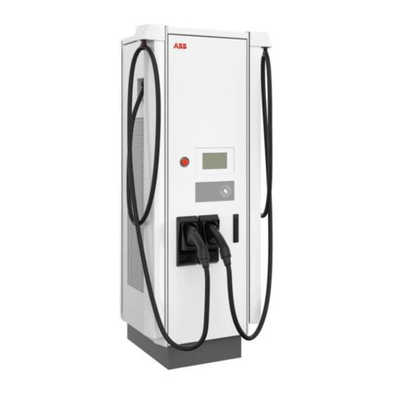
Terra 184
All-In-One 90kW DC Fast Charger
Description
This Terra all-in-one DC fast charger offers power up to 180 kW, with con-
venient charging times for every EV – including those with HV batteries.
The compact, modular design makes it perfect for retail, highway or fleet
use, with power sharing to further optimize utilization. All Terra chargers
feature connectivity for remote services and OCPP enablement.
Key Benefits and Features
•
User friendly control interface allows for PIN or RFID accessibility
•
OCPP 1.6 standard supports integration into In-Control, In-Charge's
EVSE management platform
•
LTE Modem and LAN
•
TUV Certified
Specifications
•
180kW or 90 kW x2
•
Available with Dual CCS1 or CCS1 / CHAdeMO
•
DIN 70121, ISO 15118 protocols supported
•
Dimensions: 34.6" (D) X 22.2" (W) X 74.8 x" (H) / 880mm X 565mm X 1900mm
•
Weight: 395kg / 870lbs
Ordering Information
Configuration
Terra 184 Cable Retractor - Dual CCS
Terra 184 Cable Retractor – CCS1 & CHAdeMO
SKU
ADC-180-480-C1C1-AC1R
ADC-180-480-C1CH-AC1R
The Terra 184 All-In-One
Advertisement
Table of Contents

Related Manuals for ABB InCharge Terra 184


Summary of Contents for ABB InCharge Terra 184
- Page 1 Terra 184 All-In-One 90kW DC Fast Charger Description This Terra all-in-one DC fast charger offers power up to 180 kW, with con- venient charging times for every EV – including those with HV batteries. The compact, modular design makes it perfect for retail, highway or fleet use, with power sharing to further optimize utilization.
- Page 2 Technical Specifications Configuration Voltage 480 Vac +/- 10 % AC Input Power Connection 3-phase: L1, L2, L3, GND Frequency 60 Hz Recommended breaker 300A Max Current Draw 230A Power factor >0.96 THD - Current < 5% Output Parameters Value Voltage 150 - 920Vdc Current - Max 200A...
- Page 3 Operation and installation manual Terra 94/104/124/184 North America © Copyright 2022 ABB. All rights reserved...
- Page 4 Copyright All rights to copyrights, registered trademarks, and trademarks reside with their respective owners. ® Copyright ABB EV Infrastructure. All rights reserved. 9AKK108466A3703-EN | 001...
-
Page 5: Table Of Contents
Contents Contents About this document................8 Function of this document...................... 8 Target group..........................8 Revision history..........................8 Language.............................8 Illustrations..........................8 Units of measurement......................8 Typographical conventions..................... 9 How to use this document...................... 9 General symbols and signal words..................9 1.10 Special symbols for warnings and dangers............... 10 1.11 Related documents........................ - Page 6 Contents 3.4.2 Overview of the EVSE, outside................25 3.4.3 Overview of the EVSE, inside................26 3.4.4 Overview of the cable glands of the charge post..........27 3.4.5 Overview of the installed EVSE................28 3.4.6 Overview of the cable management system (option)........28 Authorization to charge......................
- Page 7 Contents 5.3.3 Prepare a standard prefabricated foundation..........44 Replace the standard base with an alternative base............45 5.4.1 Remove the EVSE from the base................. 46 5.4.2 Install a base with side entrance................. 46 5.4.3 Install a base with reduced height...............47 Mechanical installation......................47 5.5.1 Mechanical installation procedure..............
- Page 8 Contents 6.8.1 Start the local service portal.................63 6.8.2 Set the configuration parameters...............63 6.8.3 Set the OCPP parameters..................63 6.8.4 Install new software....................64 6.8.5 Close the local service portal................64 Maintenance and cleaning..............65 Maintenance schedule......................65 Clean the cabinet........................65 Do a visual check of the EVSE....................66 Replace the air inlet filter.......................66 Replace the air outlet filter....................
- Page 9 Contents 10.12.3 Mass of the EVSE (without packaging material)..........81 10.12.4 Center of gravity......................81 10.12.5 Floor space requirements..................82 10.12.6 Casted foundation....................83 10.12.7 Prefabricated foundation..................84 10.12.8 Alternative base with side entrance..............85 10.12.9 Cable slack........................86 10.12.10 Height of user operable elements...............86 10.13 Communication interface specifications................
-
Page 10: About This Document
About this document About this document Function of this document The document is only applicable for this EVSE (Terra x4), including the variants and options listed in section 10.1. The document gives the information that is necessary to do these tasks: •... -
Page 11: Typographical Conventions
About this document Typographical conventions The lists and steps in procedures have numbers (123) or letters (abc) if the sequence is important. How to use this document 1. Make sure that you know the structure and contents of this document. 2. -
Page 12: Special Symbols For Warnings And Dangers
About this document Signal word Description Symbol Make sure that the power supply to the EVSE is disconnected. Electrotechnical expertise is required, according to the local rules. Alternating current supply Note: It is possible that not all symbols or signal words are present in this document. -
Page 13: Related Documents
800 Hymus Boulevard Saint-Laurent AZ 85284 Qc, H4S 0B5 Canada Phone: 800-435-7365 E-mail: CA-evci@us.abb.com Contact data ABB EV Infrastructure in your country can give you support on the EVSE. You can find the contact data here: https://new.abb.com/ev-charging 1.13 Abbreviations Abbreviation Definition... -
Page 14: Terminology
1.14 Terminology Term Definition Network operating center Facility of the manufacturer to do a remote check on of ABB EV Infrastructure the correct operation of the EVSE Cabinet Enclosure of the EVSE, including the components on the inside Cable slack... -
Page 15: Orientation Agreements
About this document 1.15 Orientation agreements Front side: face forward to the X-direction (positive is to the right) EVSE during normal use Y-direction (positive is rearward) Left side Z-direction (positive is upward) Right side Rear side 9AKK108466A3703-EN | 001... -
Page 16: Safety
Safety Safety Liability The manufacturer is not liable to the purchaser of the EVSE or to third parties for damages, losses, costs or expenses incurred by the purchaser or third parties if any target group mentioned in the related documents does not obey the rules below: •... -
Page 17: Required Qualifications For The Installation Engineer
Safety Required qualifications for the installation engineer • The qualified installation engineer fully knows the EVSE and its safe installation. • The installation engineer is qualified according to the applicable local rules to do the work. • The qualified installation engineer obeys all local rules and the instructions in the installation manual. -
Page 18: Safety Instructions During Transport
Safety • Make sure that the load capacity of the grid is in accordance with the EVSE. • Earth the EVSE correctly. Refer to section 2.8. • Make sure that the wiring inside the EVSE is protected from damage and cannot get trapped when you open or close the cabinet. -
Page 19: Signs On The Evse
Safety 2.10 Signs on the EVSE Symbol Risk type General risk Hazardous voltage that gives risk of electrocution Risk of pinching or crushing of body parts Rotating parts that can cause a risk of entrapment Hot surface that gives risk of burn injuries Sign that means that you must read the manual before you install the EVSE Waste from electrical and electronic equipment... -
Page 20: Cyber Security
ABB Ltd and its affiliates are not liable for damages and/or losses related to such security breaches, any unauthorized access, interference, intrusion, leakage and/or theft of data or information. -
Page 21: Description
XXXXX xxx/xxxV XW+PE ~ XXXX xxxA XXXXX XXXX xxx-xxxV XXXX xxxA XXXXX XXXX xxx-xxxV ABB B.V. George Hintzenweg 81, 3068 AX Rotterdam, The Nederlands MADE IN ITALY Prod. date xx xxxx Contains FCC ID (see note A): XXXXXXXXX; XXXXXXX Manufacturer... - Page 22 Description Danger: General risk • If you use the EVSE in any other way than described in the related documents, you can cause death, injury and damage. • Use the EVSE only as intended. 9AKK108466A3703-EN | 001...
-
Page 23: Working Principles
Description Working principles 3.3.1 Terra x4 variants CC and CJ 9AKK108466A3703-EN | 001... - Page 24 Description Main fuse Interlink contactor AC EMC filter AC SPD AC contactor RCD breaker Residual current device Auxiliary transformer Power module matrix Auxiliary breaker 30kW power module Heater DC Filter Power supply unit DC relay DC EMC filter DC fuse DC cooling fans Overcurrent board CCB board...
-
Page 25: Terra X4 Variant C
Description 3.3.2 Terra x4 variant C 9AKK108466A3703-EN | 001... -
Page 26: Overview
Description Main fuse IMI board AC EMC filter AC SPD AC contactor RCD breaker Residual current device Auxiliary transformer Power module matrix Auxiliary breaker 30kW power module Heater DC Filter Power supply unit DC relay DC EMC filter DC fuse DC cooling fans Overcurrent board CCB board... -
Page 27: Overview Of The Evse, Outside
Description Part Function The EV of which the batteries need to be charged EVSE Refer to section 10.1. Parking space Location for the EV during the charge session AC input cable To supply the electrical energy to the EVSE Power distribution board To connect the EVSE to the AC grid input EV charge cable To conduct the charge from the EVSE to the EV... -
Page 28: Overview Of The Evse, Inside
Description Part Function Border cover To cover the lower part of the EVSE EV charge cable outlet and To connect and hold the EV charge cable. Refer to sec- holder tion 3.7. RFID reader To read the information from an RFID card Payment terminal To pay for the charge session Emergency stop button... -
Page 29: Overview Of The Cable Glands Of The Charge Post
Description Part Function Cable gland plate Plate with openings for the AC input cable and the control signal cables Input AC fuse To connect or disconnect the AC power input Auxiliary AC fuse To connect or disconnect the AC power input to the auxiliary power supply breaker 1 RCD breaker To connect or disconnect the AC power input to or... -
Page 30: Overview Of The Installed Evse
Description 3.4.5 Overview of the installed EVSE EVSE Floor Base Foundation 3.4.6 Overview of the cable management system (option) Duct Gland Wheel Cable clamp Top attachment point 9AKK108466A3703-EN | 001... -
Page 31: Authorization To Charge
The touchscreen guides the user how to use the payment terminal. Note: • To use and adjust the settings of the payment terminal, you require the ABB Payment Web tool. Options 3.7.1 EV charge cable, CCS 1 The manufacturer can deliver the EVSE with CCS 1 connectors on the EV charge cables. -
Page 32: Ev Charge Cable, Ccs 2
Description 3.7.2 EV charge cable, CCS 2 The manufacturer can deliver the EVSE with CCS 2 connectors on the EV charge cables. For the current rating specifications, refer to section 10.2. For the cable length specifications, refer to section 10.12.1. 3.7.3 EV charge cable, CHAdeMO The manufacturer can deliver the EVSE with CHAdeMO connectors on the EV charge... -
Page 33: Tilt Sensors
The illustration shows the tilt sensors interface with the power distribution system of the site. Please note that the shown branch circuit breaker, 24 V DC supply delivered from an UPS, and all other components are not within the scope of ABB E-Mobility, therefore are not provided in the EVSE. -
Page 34: Power Allocation Strategies
Description Power allocation strategies The EVSE can be configured to operate with different power allocation strategies. The configuration can be changed at any time through the EVSE configuration tools. The configuration of the EVSE allows for these power allocation strategies: Power allocation strategy Available for EVSE models Reference Sequential All models... -
Page 35: Concurrent Power Allocation
Description 3.8.2 Concurrent power allocation 0 - 99% 0 - 99% When the EVSE is configured for concurrent power allocation, it can serve two EVs at a time with DC fast charging. In this configuration the EV charging power delivered by each outlet is up to half of the maximum power available to the EVSE, a maximum of half of the rated power output of the station. -
Page 36: Dynamic Power Allocation 'Fair Share
Description a second EV is connected to the EVSE, the second session can start only if the first charge session requests less than half of the power available to the station. If the first charge session requests more, the second EV must wait until the charge session can start. -
Page 37: Description Of The Touchscreen
Description Situation: the local rules require an immunity for short current peaks over PE during the EV charging process At the start of the EV charge cycle, a relay switches and engages the AC input power to the power modules. Incidental current peaks can occur. A combination of these factors is the source of these current peaks: •... -
Page 38: General Description Of The Buttons
Description 3.10.2 General description of the buttons Button Name Description To select the CCS connector CHAdeMo To select the CHAdeMo connector Language To change the language on the touchscreen. The button shows the code of the selected language. Start To start the charge session start Stop To stop the charge session... -
Page 39: Cloud Service Portal
To set the OCPP parameters, refer to section 6.8.3 3.12 Cloud service portal ABB EV Infrastructure provides a set of cloud-based tools to commission, monitor and troubleshoot the EVSE. Please refer to the manufacturer's e-Mobility representative for more information. 9AKK108466A3703-EN | 001... -
Page 40: Inspection And Transport
Inspection and transport Inspection and transport Transport the EVSE to the site A transport company delivers the EVSE close to the site. The movement of the EVSE to its final location is your responsibility. • If you need to store the EVSE before installation, obey the ambient conditions for storage. -
Page 41: Remove The Cabinet From The Pallet
Inspection and transport Procedure 1. Do a check on the sensors (A) that record the shocks during transport. TiltWatch PLUS 2. Do a check on the sensors (B) that record the maximum tilt during transport. 3. If the sensors (A) show a red ShockWatch indication or the sensors (B) show a tilt that is too high, do these steps:... -
Page 42: Move The Cabinet With A Forklift Truck
Inspection and transport • Installation engineer • Swivel eye bolts or bolts with lifting loops. Refer to section 10.6. Warning: Risk of pinching or crushing, the cabinet is heavy • Make sure that the hoisting equipment can lift the cabinet safely. Obey the safety instructions that apply to the hoisting equipment. - Page 43 Inspection and transport Procedure 1. Move the forks (A) of the forklift truck in the gaps at the side of the cabinet. 2. Move the cabinet to the correct location. 9AKK108466A3703-EN | 001...
-
Page 44: Installation
Installation Installation General installation procedure Preliminary requirements • All required permits to • Tools for installation. Refer obey the local rules are to section 10.5. granted. • The AC input cable is available. • • There is no voltage on the AC input cable during the complete installation procedure. -
Page 45: Control The Space And Airflow Around The Cabinet
Installation Procedure 1. Select a suitable site: a. Make sure that the space and the airflow around the cabinet is sufficient. Refer to section 5.2.2. b. Design the site so that the charge cables are of sufficient length for connection at the inlet for the EV charge cables on the EVs. For the length of the charge cables, refer to section 10.12.1. -
Page 46: Prepare The Foundation
Installation Prepare the foundation 5.3.1 Prepare the foundation - general procedure Preliminary requirements • Installation engineer Procedure 1. Select the correct foundation, based on the surface you install the cabinet on. 2. Embed the cables in the ground with or without a cable duct. Refer to the local rules. -
Page 47: Replace The Standard Base With An Alternative Base
Installation Procedure 1. Make the foundation (A). Do one of these steps: • Contact the manufacturer to order the foundation for your EVSE. Refer to section 1.12. • Make the foundation according to the specifications. 2. Dig the hole (B) for the foundation (C). For the specifications, refer to section 10.12.7. -
Page 48: Remove The Evse From The Base
Installation 5.4.1 Remove the EVSE from the base Generally the base replacement is done during the installation procedure, when the EVSE is still on the shipping pallet. Preliminary requirements • Installation engineer or • Wrenches maintenance engineer Procedure 1. Open all doors of the EVSE. Refer to section 8.1. -
Page 49: Install A Base With Reduced Height
Installation 5.4.3 Install a base with reduced height Preliminary requirements • Installation engineer or • Base with reduced height. maintenance engineer • Wrenches This procedure is relevant if you want to obey the regulations for wheelchair accessibility and the combination of the location of the installation and the standard base does not allow for this. -
Page 50: Open The Cable Inlet And Remove The Cable Gland
Installation 5.5.2 Open the cable inlet and remove the cable gland Preliminary requirements • Installation engineer • Open spanner. Refer to section 10.5. Procedure 1. Open the front and right doors. Refer to section 8.1. 2. Loosen the fasteners (A). 3. -
Page 51: Electrical Installation
Installation • Open spanner. Refer to section 10.5. Procedure 1. Carefully lower the cabinet on the foundation. Refer to section 4.3. Make sure that the holes in the cabinet (A) and the foundation (B) are aligned. Caution: Make sure that there is no kink in the cables. -
Page 52: Connect The Enclosure To The Earth
Installation • Wire stripper pliers, cable lug tool and torque socket wrench. Refer to section 10.5. Procedure 1. Prepare the wire: a. Cut the PE wire (A). Make sure that the length is sufficient for connection at the PE busbar (B). b. -
Page 53: Connect The Ac Input Wires
Installation 5.6.4 Connect the AC input wires Preliminary requirements • The front and right doors • Cable lugs and fasteners. are open. Refer to section 10.6. • • Installation engineer • Wire stripper pliers, cable lug tool and torque socket wrench. -
Page 54: Tilt Sensors Installation (Option)
Installation Procedure 1. Connect the Ethernet cable (A) to the Ethernet RJ45 socket (B). Note: Daisy chaining of Ethernet between the EVSEs or network points is not supported. Tilt sensors installation (option) 5.7.1 General procedure For all specifications of the tilt sensors, refer to section 10.10. 1. -
Page 55: Install The Tilt Sensors
Installation Procedure 1. Install the tilt switch (A) on the bracket (B). Install the fasteners from the top downwards. 2. Install the bracket in the main plate (C). Install the fasteners. 3. If the main plate does not have fixing holes for the tilt sensor bracket, use a second temporary bracket and an UL fan mounting hole. -
Page 56: Install A Ferrule On A Wire
Installation Procedure 1. Prepare the wires. Refer to section 5.7.5. 2. Loosen the screws of the terminal block. 3. Connect these wires. : 1. V+ wire from the external customer interface, to the terminal V+. 2. Ground wire from the external customer interface, to the terminal GND. 3. -
Page 57: Cable Management System Installation (Option)
Installation Procedure 1. Loosen the screw of the connection on the terminal. 2. Install the ferrule in the connection of the terminal. 3. Tighten the screw to the correct torque. For the specifications, refer to section 10.7. 4. Make sure that unused wires are protected and cannot touch metal parts. -
Page 58: Mount The Clamp
Installation 5.8.2 Mount the clamp For the specifications for the cable management system, refer to section 10.11. 1. Pull the wire and hold it firmly. At the same time connect the clamp to the wire. Apply a knot. The correct location for mounting the clamp is at approximately half way on the EV charge cable. - Page 59 Installation Procedure 1. Tell the owner that the EVSE is ready for commissioning. 2. Make sure that the site complies with these requirements: • The EVSE is installed. • AC input power is available from the grid provider. • You are present during the commissioning, for assistance and to energize the power to the EVSE on the power distribution board.
-
Page 60: Operation
Operation Operation Prepare before use Preliminary requirements • Owner Procedure 1. Make sure that the EVSE is installed according to the instructions in this manual. 2. Make an emergency plan that instructs people what to do in case of an emergency. -
Page 61: Reset The Evse After An Emergency
Operation Reset the EVSE after an emergency Preliminary requirements • Owner Procedure 1. Make sure that the situation is safe again. 2. Turn the emergency button clockwise to release it. • The EVSE starts. • The message disappears from the touchscreen. •... -
Page 62: Stop A Charge Session
Operation 6.4.3 Stop a charge session Preliminary requirements • Owner Procedure stop button. 1. On the touchscreen, press the Note: When the battery is full, the charge session stops automatically. 2. If the touchscreen shows a message to authorize the charge session, do the instruction that the touchscreen shows. -
Page 63: Measure The Ac Voltage
Operation Procedure 1. Set the upstream breaker which provide the power to this EVSE to OFF and lock it. Make sure that this breaker stays in the OFF position during the procedure. 2. Open the front door and the right door. Refer to section 8.1. 3. -
Page 64: Remove Condensation From The Cabinet
Operation Procedure 1. Measure the DC voltage between the output terminals: • Power module group output 1- (A) to power module group output 1+ • Power module group output 2- (C) to power module group output 2+ • EV charge cable 1 output - (E) to EV charge cable 1 output + (F) •... -
Page 65: Local Service Portal Operations
Operation Local service portal operations 6.8.1 Start the local service portal Preliminary requirements • The EVSE is ready for operation. No charge session is in progress. • No charge session is in progress. Procedure 1. Open the front door of the EVSE. Refer to section 8.1. The HMI starts the local service portal application. -
Page 66: Install New Software
Operation 6.8.4 Install new software Trigger discovery . 1. On the hardware screen, select The screen gives feedback if the trigger discovery has been started or failed. The system tries to discover new hardware, installs software on the hardware and assigns node IDs. During this discovery, the local service portal is closed. Out of order . -
Page 67: Maintenance And Cleaning
Maintenance and cleaning Maintenance and cleaning Maintenance schedule Task Frequency Procedure Clean the cabinet. 4 months Refer to section 7.2. Do a check for damage on 3 months Refer to section 7.3. the EV charge cables and the connectors. Do a check for damage on 6 months Refer to section 7.3. -
Page 68: Do A Visual Check Of The Evse
Maintenance and cleaning 3. Manually remove dirt. Use the non-abrasive tool. Caution: Do not use abrasive tools. There is a risk of damage to the finish of the EVSE, that can cause deep corrosion and structural damages. 4. Rinse with low-pressure tap water. 5. -
Page 69: Replace The Air Outlet Filter
Maintenance and cleaning Procedure 1. De-energize the EVSE. Refer to section 6.6. 2. Open the left and right doors. Refer to section 8.1. 3. Loosen the nuts (A). Use the spanner. 4. Carefully remove theses parts: 1. Cover (B) 2. Air inlet filter (C) Caution: Prevent contamination of other parts of the EVSE. - Page 70 Maintenance and cleaning 5. Carefully pull and remove the outlet filter (C). Caution: Prevent contamination of other parts of the EVSE. Make sure that contamination on the filter does not come off. 6. Install the new air outlet filter. Make sure that the air flow direction that is indicated on the air outlet filter corresponds with the air flow.
-
Page 71: Access To Parts
Access to parts Access to parts Open the doors Preliminary requirements • Installation engineer • Door key • Owner Danger: Hazardous voltage • Make sure that only qualified persons have access to the door key. Note: There is one unique door key for each cabinet. Procedure 1. -
Page 72: Remove The Border Covers
Access to parts Note: There is one unique door key for each cabinet. Procedure 1. If the left or right doors (A) are open, close the doors through the opening of the front door. 2. Close the front door (B). 3. -
Page 73: Install The Border Covers
Access to parts Install the border covers Preliminary requirements • Installation engineer • Set of hex keys Note: This procedure is only valid for a standard base or a base with side entrance. Procedure 1. Install these parts: 1. Border covers (A) 2. -
Page 74: Troubleshooting
Troubleshooting Troubleshooting Troubleshooting procedure 1. Try to find a solution for the problem with the aid of the information in this document. 2. If you cannot find a solution for the problem, contact your local representative of the manufacturer. Refer to section 1.12. Troubleshooting table Problem Possible cause... -
Page 75: Technical Data
Technical data Technical data 10.1 EVSE type The EVSE type is a code that has 7 parts Part description Value Meaning of the value Brand Terra Model and design genera- Fourth generation charger, 90 kW DC tion output: 3 power modules installed Fourth generation charger, 100 kW DC output: 4 power modules installed Fourth generation charger, 120 kW DC... -
Page 76: Parts Included In The Delivery
Technical data Parameter Specification FCC Part 15 Class A FCC Part 22, FCC Part 27 RSS-132 Issue 3, RSS-139 Issue 3, RSS-199 Issue 6 CHAdeMO 1.2 IP rating The type plate shows the specification. Refer to section 3.1. IK rating according to IEC 62262: enclo- IK10 sure IK rating according to IEC 62262:... -
Page 77: Required Tools For Installation
Technical data 10.5 Required tools for installation Parameter Specification [mm] [in] Philips screwdriver Size: PH2 Size: PH2 Slot screwdriver Size: 2.5 and 4.5 Size: 0.1 and 0.18 Hex keys Size: 5, 5.5 and 6 Size: 0.2, 0.22 and 0.24 Torx screwdriver Size: 15, 20 and 25 Size: 0.59, 0.79 and 0.98 Torx angled or bit with... -
Page 78: Torque Specifications
Technical data 10.7 Torque specifications Parameter Specification [Nm] [lb-in] Fasteners for the PE wire Between 33 and 44 Between 292 and Fasteners for the L1, L2, L3 wires Between 33 and 44 Between 292 and Fasteners for an alternative base Between 33 and 44 Between 292 and Fasteners for the tilt sensors 11.5... -
Page 79: Wire Specifications
Technical data 10.10.2 Wire specifications Tilt sensor cables Specifications Number of cores One twisted pair (total of two cores) Diameter of cores 18 AWG Diameter outside 5 to 10 mm (0.20 to 0.39 in) Conductor Fine strand copper wire Insulation PVC or other material that is serviceable for outdoor use and UV-protected Minimum test... -
Page 80: The Alternative Base With Reduced Height
Technical data Parameter Specification Signal description TB label Grey cable Tilt switch NC con- tact Blue cable Tilt switch COM contact 10.10.4 The alternative base with reduced height Front side of the base Distance between the 4 fixation Width of the base holes Distance between the outer Distance between the outer... -
Page 81: Cable Management System Specifications
See * 200 A * The maximum cable length supported by the ABB cable retraction system is 6 m (20 ft). If the EVSE is equipped with a cable longer than 8 m (26 ft) the EVSE is not compliant with NEC 625.17. An external cable management system must be installed to comply with the standard. -
Page 82: Dimensions
[ft] Length of the charge cable (air-cooled) * The maximum cable length supported by the ABB cable retraction system is 6 m (20 ft). If the EVSE is equipped with a cable longer than 8 m (26 ft) the EVSE is not compliant with NEC 625.17. -
Page 83: Mass Of The Evse (Without Packaging Material)
Technical data 10.12.3 Mass of the EVSE (without packaging material) Parameter Specification [kg] [lb] Terra 94 Terra 104, 124 Terra 184 Cable management system (optional) for one cable, no counterweight* Cable management system (optional) for two cables, no counterweight* Cable management system (optional), single counterweight* * The number of counterweights depends on the cable installed on the EVSE. -
Page 84: Floor Space Requirements
Technical data Note: • The coordinates correspond with the agreements in section 1.15. 0,0,0 is the left bottom front side of the EVSE. • The values for the center of gravity refer to an EVSE with a standard base. 10.12.5 Floor space requirements Cabinet Free space required on the sides of... -
Page 85: Casted Foundation
Technical data 10.12.6 Casted foundation Holes to install the fasteners of the Addtional holes EVSE Front of the EVSE Conduit stub up Parameter Specification [mm] [in] M10, depth 60 M10, depth 2.4 25-50 50-75 22.2 36.5 34.6 12.8 9AKK108466A3703-EN | 001... -
Page 86: Prefabricated Foundation
Technical data 10.12.7 Prefabricated foundation Prefabricated foundation Width of the hole Hole for the foundation Depth of the hole Width of the foundation Height of the hole Depth of the foundation Distance of the foundation above Height of the foundation the ground level Parameter Specification... -
Page 87: Alternative Base With Side Entrance
Technical data 10.12.8 Alternative base with side entrance Front side of the base Depth of the base including the Width of the base fasteners Distance between the outer Distance between the outer fixation holes fixation holes Distance between 2 fixation holes Distance between the middle Depth of the base fixation holes... -
Page 88: Cable Slack
Technical data 10.12.9 Cable slack Parameter Specification [mm] [in] Required cable slack for the Ethernet ca- ble (measured from the top of the foun- dation) Required cable slack for the AC input ca- ble (measured from the top of the foun- dation) 10.12.10 Height of user operable elements... -
Page 89: Communication Interface Specifications
Technical data Parameter Specification Standard Base with reduced height [mm] [in] [mm] [in] < 100 < 4 ADA compliance According to ADA (Act of Disabled Americans) the height of user operable elements must be between specific limits: • Maximum height is 1219 mm (44 in) •... -
Page 90: Evse Power Rating
Technical data 10.14 EVSE power rating 10.14.1 EVSE rating during normal duty operation Normal duty operation applies for use in public applications with moderate traffic. Parameter Specification [kW] Terra 94 Terra 104 Terra 124 Terra 184 10.14.2 EVSE derating during normal duty operation The table shows the steady state rating of the EVSE at specific ambient temperatures. -
Page 91: Harmonics On The Grid
Technical data Parameter Specification Ambient temperature Power Output [%] De-rating [%] [°C] [°F] -35 ... + 35 -31 … +95 + 36 … + 40 +96 …+104 + 41 … + 45 +105 …+113 + 46 … + 50 +114 …+122 + 51 …... - Page 92 Technical data Order Phase L1 Phase L2 Phase L3 IRMS IRMS IRMS 0.73 0.32 0.88 0.39 0.78 0.35 0.23 0.10 0.19 0.09 0.16 0.07 0.08 0.03 0.05 0.02 0.16 0.07 0.15 0.07 0.22 0.10 0.25 0.11 0.67 0.30 0.60 0.27 0.75 0.33 0.18...
-
Page 93: Terra 124 And 104
Technical data 10.15.2 Terra 124 and 104 Working Electric (L1/L2/L3) (L1/L2/L3) point load 900 V / 100 % 0.747 % 0.667 % 0.740 % 2837 % 2889 % 2838 % 133A Order Phase L1 Phase L2 Phase L3 IRMS IRMS IRMS 150.84 100.00... -
Page 94: Terra 94
Technical data Order Phase L1 Phase L2 Phase L3 IRMS IRMS IRMS 0.04 0.03 0.03 0.02 0.11 0.07 0.04 0.03 0.08 0.06 0.09 0.06 0.33 0.22 0.36 0.24 0.38 0.25 0.07 0.05 0.09 0.06 0.15 0.10 0.34 0.23 0.31 0.21 0.33 0.22 0.06... - Page 95 Technical data Order Phase L1 Phase L2 Phase L3 IRMS IRMS IRMS 0.06 0.06 0.05 0.05 0.03 0.03 0.16 0.14 0.16 0.14 0.14 0.12 0.07 0.07 0.13 0.11 0.18 0.16 0.34 0.30 0.43 0.39 0.41 0.36 0.12 0.10 0.10 0.09 0.06 0.06 0.07...
-
Page 96: Ac Input Specifications
Technical data Order Phase L1 Phase L2 Phase L3 IRMS IRMS IRMS 0.10 0.09 0.12 0.11 0.20 0.17 0.08 0.07 0.11 0.10 0.10 0.09 0.04 0.04 0.06 0.05 0.08 0.07 Total 112.69 2816% 112.36 2976% 112.53 2804% 10.16 AC input specifications 10.16.1 General AC input specifications Parameter... -
Page 97: Ac Input Wires
Technical data Parameter Specification Input voltage A 480 V Input voltage B 277 V The EVSE must be wired with a WYE input, as shown in the diagram. Do not connect a neutral wire to the EVSE. 10.16.2 AC input wires Parameter Specification Wire shielding (optional) -
Page 98: Terra 124
Technical data Note: Power limiting is possible via software configuration. 10.16.5 Terra 124 Parameter Specification Maximum rated input current 153 A Recommended input circuit breaker 200 A Maximum power dissipation 127.2 kVA Short circuit current rating 65 kA Maximum size of the input wire 500 kcmil Note: Power limiting is possible via software configuration. -
Page 99: Terra 104
Technical data 10.17.2 Terra 94 Parameter Specification DC output power on one EV charge cable Maximum 90 kW Simultaneous DC on two outlets No. One DC output operates at a time. Maximum DC output current CCS: 200 A or 300 A (high current model) CHAdeMO: 200 A Output current in function of output voltage 1000... - Page 100 Technical data Output power in function of output voltage 1000 output voltage (V) CCS (200A) CCS High Current (300A) CHAdeMO (200A) CHAdeMO 200 A 200 A High Current 300 A Current [A] Power [kW] Current [A] Power [kW] Current [A] Power [kW] 10.17.3 Terra 104...
- Page 101 Technical data Output current in function of output voltage (one charge session) 900 1000 output voltage (V) CCS (200A) CCS High Current (400A) CHAdeMO (200A) Charger Capacity Voltage [V] Current [A] Power [kW] 9AKK108466A3703-EN | 001...
- Page 102 Technical data Output power in function of output voltage (one charge session) 900 1000 output voltage (V) CCS (200A) CCS High Current (400A) CHAdeMO (200A) CHAdeMO 200 A 200 A High Current 400 A Current [A] Power [kW] Current [A] Power [kW] Current [A] Power [kW]...
- Page 103 Technical data Output current in function of output voltage (two charge sessions) 900 1000 output voltage (V) CCS (200A) CCS High Current (400A) CHAdeMO (200A) Charger Capacity Voltage [V] Current [A] Power [kW] 9AKK108466A3703-EN | 001...
-
Page 104: Terra 124
Technical data Output power in function of output voltage (two charge sessions) 900 1000 output voltage (V) CCS (200A) CCS High Current (400A) CHAdeMO (200A) CHAdeMO 200 A 200 A High Current 400 A Current [A] Power [kW] Current [A] Power [kW] Current [A] Power [kW]... - Page 105 Technical data Output current in function of output voltage (one charge session) 1000 output voltage (V) CCS (200A) CCS High Current (400A) CHAdeMO (200A) Charger Capacity Voltage [V] Current [A] Power [kW] 9AKK108466A3703-EN | 001...
- Page 106 Technical data Output power in function of output voltage (one charge session) 1000 output voltage (V) CCS (200A) CCS High Current (400A) CHAdeMO (200A) CHAdeMO 200 A 200 A High Current 400 A Current [A] Power [kW] Current [A] Power [kW] Current [A] Power [kW] 9AKK108466A3703-EN | 001...
- Page 107 Technical data Output current in function of output voltage (two charge sessions) 1000 output voltage (V) CCS (200A) CCS High Current (400A) CHAdeMO (200A) Charger Capacity Voltage [V] Current [A] P [kW] 9AKK108466A3703-EN | 001...
-
Page 108: Terra 184
Technical data Output power in function of output voltage (two charge sessions) 1000 output voltage (V) CCS (200A) CCS High Current (400A) CHAdeMO (200A) CHAdeMO 200 A 200 A High Current 400 A Current [A] Power [kW] Current [A] Power [kW] Current [A] Power [kW] 10.17.5... - Page 109 Technical data Output current in function of output voltage (one charge session) 1000 output voltage (V) CCS (200A) CCS High Current (400A) CHAdeMO (200A) Charger Capacity Voltage [V] Current [A] Power [kW] 9AKK108466A3703-EN | 001...
- Page 110 Technical data Output power in function of output voltage (one charge session) 1000 output voltage (V) CCS (200A) CCS High Current (400A) CHAdeMO (200A) CHAdeMO 200A 200A High Current 400A Current [A] Power [kW] Current [A] Power [kW] Current [A] Power [kW] 9AKK108466A3703-EN | 001...
- Page 111 Technical data Output current in function of output voltage (two charge sessions) 1000 output voltage (V) CCS (200A) CCS High Current (400A) CHAdeMO (200A) Charger Capacity Voltage [V] Current [A] Power [kW] 9AKK108466A3703-EN | 001...
-
Page 112: Power Consumption
Technical data Output power in function of output voltage (two charge sessions) 1000 output voltage (V) CCS (200A) CCS High Current (400A) CHAdeMO (200A) CHAdeMO 200A 200A High Current 400A Current [A] Power [kW] Current [A] Power [kW] Current [A] Power [kW] CHAdeMO CCS (200A) -
Page 113: In-Rush Current
Technical data Note: The heater will operate daily when the outside air reaches the dew point, to avoid condensation inside the cabinet. When the heater operates, the heater will use most of the required standby power. 10.19 In-rush current Current peaks during the start of a charge session Parameter Specification [µs] Duration of the current peaks on the AC... -
Page 114: Cleaning Specifications
Technical data Part name Years after startup 10 11 12 13 14 15 CPI Combo CCS CPI CHAdeMO Touchscreen/ DC outlet con- tactor Power supply CCS connector and cable CHAdeMO con- nector and cable Gun holders • 'I' = Inspection or other procedure •... - Page 115 Technical data Part Name Quantity CCS connector and cable 1 x Terra x4 C/CJ 2 x Terra x4 CC CHAdeMO connector and cable 1 x Terra x4 CJ 2 x Terra x4 JJ Gun holder 1 x for CCS type 1 UL connection 1 x for CCS type 2 CE connection 1 x for ChadeMo connection Rain cap for the gun holder...
-
Page 116: Appendix
Appendix Appendix 11.1 Declaration of conformity 9AKK108466A3703-EN | 001... - Page 117 Appendix 9AKK108466A3703-EN | 001...