
Related Manuals for ABB Terra HP Generation 3


Summary of Contents for ABB Terra HP Generation 3
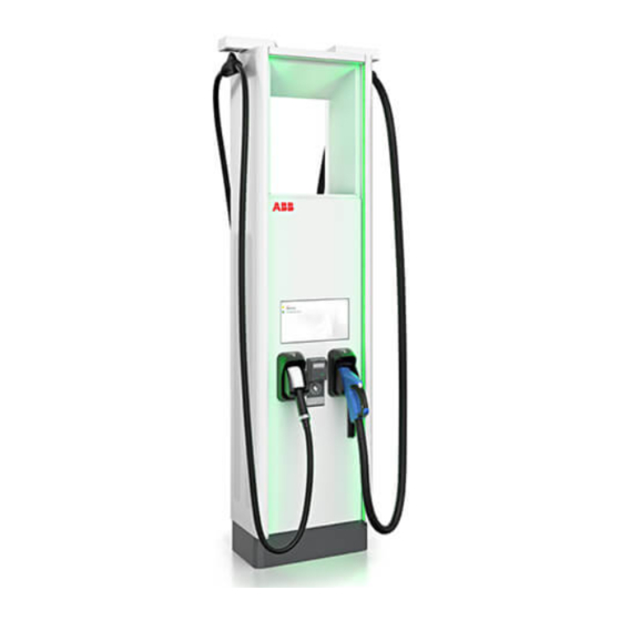
- Page 1 Installation manual Terra HP Generation 3 UL 175 kW Static DC system © Copyright ABB. All rights reserved...
- Page 2 Copyright All rights to copyrights, registered trademarks, and trademarks reside with their respective owners. ® Copyright ABB EV Infrastructure. All rights reserved. 9AKK107992A3069-EN | 004...
-
Page 3: Table Of Contents
Contents Contents About this document................8 Function of this document...................... 8 Target group..........................8 Revision history..........................8 Language.............................8 Illustrations..........................8 Units of measurement......................8 Typographical conventions..................... 8 How to use this document...................... 8 General symbols and signal words..................9 1.10 Special symbols for warnings and dangers............... 10 1.11 Related documents......................... - Page 4 Contents 3.5.5 Charge post CP500 Generation 3, inside............24 3.5.6 Overview of the cable glands of the charge post..........25 Pre-installation.................. 26 Pre-installation procedure (site planning)................. 26 Prepare the site........................26 Make sure that the floor space for the EVSE and the airflow around the EVSE is correct............................
- Page 5 Contents 6.3.4 Install the cable gland plates................43 Electrical installation of the power cabinet........44 General procedure........................44 Connect the PE cables to the power cabinet..............44 Connect the AC input cables....................45 Connect the DC power cables....................46 Connect the AC auxiliary power cable in the primary power cabinet......47 Connect the interlock and DC guard cables to the power cabinet.......
- Page 6 Contents Technical data..................67 12.1 EVSE type..........................67 12.2 Parts included in the delivery....................67 12.3 Required tools for installation....................68 12.4 Required parts for installation..................... 68 12.5 General specifications......................69 12.6 Electrical installation specifications (North America)............. 69 12.7 Electrical installation specifications (Canada)..............70 12.8 DC output specifications.......................
- Page 7 Contents 12.19.6 Optical CAN cables between the power cabinet and the charge post..97 12.19.7 Ethernet cable......................97 12.20 Expected wye input.........................98 12.21 Electrical connection diagram....................99 9AKK107992A3069-EN | 004...
-
Page 8: About This Document
About this document Function of this document The document is only applicable for this EVSE: Terra HP Generation 3, including the variants and options listed in section 12.1. The document gives the information that is necessary to install the EVSE. -
Page 9: General Symbols And Signal Words
About this document 3. Do the steps in the procedures fully and in the correct sequence. 4. Keep the document in a safe location that you can easily access. This document is a part of the EVSE. General symbols and signal words Signal word Description Symbol... -
Page 10: Special Symbols For Warnings And Dangers
About this document Signal word Description Symbol Electrotechnical expertise is required, according to the local rules. Alternating current supply Note: It is possible that not all symbols or signal words are present in this document. 1.10 Special symbols for warnings and dangers Symbol Risk type General risk... -
Page 11: Manufacturer And Contact Data
Manufacturer ABB EV Infrastructure George Hintzenweg 81 3068 AX, Rotterdam The Netherlands Contact data ABB EV Infrastructure in your country can give you support on the EVSE. You can find the contact data here: https://new.abb.com/ev-charging 1.13 Abbreviations Abbreviation Definition Alternating current... -
Page 12: Terminology
1.14 Terminology Term Definition Network operating center Facility of the manufacturer to do a remote check on of ABB EV Infrastructure the correct operation of the EVSE Cabinet Enclosure of the EVSE, including the components on the inside Cable slack... -
Page 13: Orientation Agreements
About this document 1.15 Orientation agreements Front side: face forward to the X-direction (positive is to the right) EVSE during normal use Y-direction (positive is rearward) Left side Z-direction (positive is upward) Right side Rear side 9AKK107992A3069-EN | 004... -
Page 14: Safety
Safety Safety Liability The manufacturer is not liable to the purchaser of the EVSE or to third parties for damages, losses, costs or expenses incurred by the purchaser or third parties if any target group mentioned in the related documents does not obey the rules below: •... -
Page 15: Personal Protective Equipment
Safety Personal protective equipment Symbol Description Protective clothing Safety gloves Safety shoes Safety glasses Safety instructions during transport Preliminary requirements Installation engineer • • Make sure that the hoisting equipment or forklift truck can lift the EVSE safely. Take into account the mass and the center of gravity of the EVSE. •... -
Page 16: Safety Instructions For Earthing
Safety • Make sure that the load capacity of the grid is in accordance with the EVSE. • Earth the EVSE correctly. Refer to section 2.7. • Make sure that the wiring inside the EVSE is protected from damage and cannot get trapped when you open or close the cabinet. -
Page 17: Discard The Evse Or Parts Of The Evse
Safety Symbol Risk type Sign that means that you must read the manual before you install the EVSE Waste from electrical and electronic equipment Note: It is possible that not all symbols are present on the EVSE. Discard the EVSE or parts of the EVSE Incorrect waste handling can have a negative effect on the environment and human health due to potential hazardous substances. - Page 18 Safety ABB Ltd and its affiliates are not liable for damages and/or losses related to such security breaches, any unauthorized access, interference, intrusion, leakage and/or theft of data or information. 9AKK107992A3069-EN | 004...
-
Page 19: Description
The properties of the electrical grid, the ambient conditions and the EV must comply with the technical data of the EVSE. Refer to chapter 12. • Only use the EVSE with accessories that are approved by the manufacturer (ABB EV Infrastructure) and that obey the local rules. •... -
Page 20: General Description Of The Evse
Description Note: The data in the illustration are only examples. Find the type plate on your EVSE to see the applicable data. Refer to section 3.5.4. General description of the EVSE The EVSE is an arrangement of these parts: • Distribution board •... -
Page 21: Overview And Functions
Description Lines Description AC input power connections DC power connections Control lines (general) Overview and functions 3.5.1 Power cabinet, outside Plinth cover Door Air outlet Air inlet (4x) Type plate Enclosure 9AKK107992A3069-EN | 004... -
Page 22: Power Cabinet, Inside
Description 3.5.2 Power cabinet, inside DC output busbars X-10 terminal block Cable inlets X-8 terminal block PE busbar CAN2FIBER device AC power connector Relays Fuse block Part Function DC output busbar To connect the DC output power cables Cable inlet A plate with openings for cables PE busbar To connect PE cables... -
Page 23: Dc Output Busbar In A Static Dc System
Description 3.5.3 DC output busbar in a static DC system Positive DC output busbar Negative DC output busbar 3.5.4 Charge post CP500 Generation 3, outside EV charge cable Cable retraction system RFID reader and the payment Enclosure terminal (option) Air inlet and outlet Connector holder Type plate Touchscreen... -
Page 24: Charge Post Cp500 Generation 3, Inside
Description 3.5.5 Charge post CP500 Generation 3, inside Cooling unit Q1 RCD (residual current circuit DC power busbars breaker) Cable gland plates X-10 terminal block PE busbar X-20 terminal block CAN2FIBER device Part Function Cooling unit To decrease the temperature of the charge cables DC power busbars To connect the DC power cables Cable gland plates... -
Page 25: Overview Of The Cable Glands Of The Charge Post
Description 3.5.6 Overview of the cable glands of the charge post PE wire Interlock and DC guard cable AC auxiliary power cable Ethernet cable PE wire DC+ in cable PE wire DC+ in cable CAN cable (SAE J1939-11) DC- in cable Not used DC- in cable 9AKK107992A3069-EN | 004... -
Page 26: Pre-Installation
Pre-installation Pre-installation Pre-installation procedure (site planning) Preliminary requirements All required permits to comply with the local rules, are granted. Procedure 1. Do a check on the configuration of the EVSE. Refer to the order. 2. Refer to the specifications to prepare and order these items: •... -
Page 27: Make Sure That The Floor Space For The Evse And The Airflow Around The Evse Is Correct
Pre-installation 7. Make sure that the site complies with the relevant usability standards, such as ADA and DIN 18040: a. Limit the curb heights. b. Take into account the limited reach of a wheelchair user. For usability standards specifications, refer to section 12.15.3. 8. -
Page 28: Prepare A Metal Foundation For The Power Cabinet
Pre-installation Procedure 1. Contact the manufacturer to order the foundation for your EVSE. Refer to section 1.12. 2. Dig the hole for the foundation. Caution: Make sure that the top surface of the foundation is above the ground level, to prevent intrusion of water. -
Page 29: Prepare A Custom Foundation For The Power Cabinet
Pre-installation Procedure 1. Mark the position of the holes (B) on the ground. For the specifications, refer to section 12.16.1. 2. Drill and thread the holes. Do not make holes in not authorized locations, because this can compromise the structural integrity of the metal foundation. -
Page 30: Prepare A Prefab Concrete Foundation For The Charge Post
Pre-installation 4.4.5 Prepare a prefab concrete foundation for the charge post Preliminary requirements • Prefab concrete foundation. Refer to section 12.17.5. Procedure 1. Contact the manufacturer to order the foundation for your EVSE. Refer to section 1.12. 2. Dig the hole for the foundation. Caution: •... -
Page 31: Prepare A Metal Foundation
Pre-installation 4.4.6 Prepare a metal foundation Preliminary requirements • Drill with screw tap • Metal frame. Refer to section 12.17.6. • Torque wrench If you have not included the foundation in the initial order, contact the manufacturer to order the foundation for your power cabinet. - Page 32 Pre-installation Procedure 1. Make the custom foundation. Caution: Make sure that the top surface of the foundation is above the ground level, to prevent intrusion of water. 2. Guide the cables into the holes (C1) to (C4) of the foundations. For the relation between the cables and the holes, refer to section 12.17.8.
-
Page 33: Inspection And Transport
Inspection and transport Inspection and transport Transport the EVSE to the site A transport company delivers the EVSE close to the site. The movement of the EVSE to its final location is your responsibility. • If you need to store the EVSE before installation, obey the ambient conditions for storage. -
Page 34: Remove The Cabinet From The Pallet
Inspection and transport Remove the cabinet from the pallet Preliminary requirements • Open spanner Procedure 1. Remove the fasteners (A). 2. Discard the fasteners and the pallet. Refer to section 2.9. Transport the EVSE on the site 5.6.1 General transport procedure Preliminary requirements The cabinets are unpacked. -
Page 35: Tilt The Charge Post To The Vertical Position
Inspection and transport Procedure 1. Move the power cabinet to the installation location: • Move the cabinet with a forklift truck. Refer to section 5.6.3. • Hoist the cabinet. Refer to section 5.6.4. 2. Move the charge post to the installation location: Situation Procedure Tilt the charge post to the vertical... -
Page 36: Move The Cabinet With A Forklift Truck
Inspection and transport 5.6.3 Move the cabinet with a forklift truck Preliminary requirements The cabinet is unpacked. • Forklift truck. Refer to Refer to section 5.4. section 12.3. Warning: Risk of pinching or crushing, the cabinet is heavy • Make sure that the forklift truck can lift the cabinet safely. Obey the safety instructions that apply to the forklift truck. - Page 37 Inspection and transport Caution: • Do not drop the cabinet. • Make sure that there are no dynamic forces on the hoisting points. • Make sure that the weight is equally distributed between the hoisting points. Procedure 1. Install the swivel eye bolts or bolts with lifting loops (A).
-
Page 38: Installation
Installation Installation General installation procedure Preliminary requirements The AC input cable is • There is no voltage on the available. AC input cable during the complete installation The foundations for the procedure. cabinets are prepared. All cables are in the cable conduits and the full cable slack is applied. -
Page 39: Install The Cabinet On The Foundation
Installation 6.2.2 Install the cabinet on the foundation Preliminary requirements • Hoisting equipment or • Four fasteners M16 and forklift truck washers • Torque wrench Procedure 1. Carefully lower the cabinet on the foundation with a hoisting equipment or a forklift truck. Refer to section 5.6.1. -
Page 40: Guide The Cables To The Cabinet
Installation 6.2.4 Guide the cables to the cabinet Preliminary requirements The cable inlets are open. Procedure 1. Guide the AC input cable, the AC auxiliary power cable, the interlock and DC guard and the CAN cables (A) through the opening (B). 2. -
Page 41: Install The Cover Plates (Metal Foundation)
Installation Procedure 1. Install the cover plate (B) on the foundation (A). 2. Install the fasteners (C). 3. Tighten the fasteners to the correct torque. For the specification, refer to section 12.14. 6.2.7 Install the cover plates (metal foundation) Preliminary requirements The cabinet is installed on •... -
Page 42: Remove The Cable Gland Plates
Installation Warning: Make sure that you secure the load when you do work below the charge post. Obey all related local regulations. Note: The manufacturer installed the cooling unit at the factory, including the cooling liquid. Procedure 1. Get access to the charge post: a. -
Page 43: Install The Charge Post On The Foundation
Installation 6.3.3 Install the charge post on the foundation Preliminary requirements • Hoisting equipment or • Six fasteners M12 and forklift truck washers • Torque wrench • Drop in anchors, for easy installation and quality Procedure 1. Carefully lower the charge post on the foundation with a hoisting equipment or a forklift truck. -
Page 44: Electrical Installation Of The Power Cabinet
Electrical installation of the power cabinet Electrical installation of the power cabinet General procedure Note: For a detailed overview of the electrical connections, refer to section 12.21. Preliminary requirements The DC cables are • installed in one of the cable conduits. Refer to section 12.18. -
Page 45: Connect The Ac Input Cables
Electrical installation of the power cabinet Procedure 1. Cut the PE cables to make sure that the length is sufficient for connection to the PE busbar (A) with a loop. The loop is necessary to make sure that the PE cable is not the first cable that is disconnected when a collision moves the power cabinet. -
Page 46: Connect The Dc Power Cables
Electrical installation of the power cabinet Procedure 1. Prepare the cables: a. Cut the AC power cables to make sure that the length is sufficient for connection at the busbar bolts (A). b. Strip the insulation from the end of the cables (C), (D) and (E). Make sure that the strip length is compatible with the cable lugs. -
Page 47: Connect The Ac Auxiliary Power Cable In The Primary Power Cabinet
Electrical installation of the power cabinet 5. Install the nuts and washers on the connector block bolts. 6. Tighten the nuts to the correct torque. For the specification, refer to section 12.14. Connect the AC auxiliary power cable in the primary power cabinet Preliminary requirements •... -
Page 48: Connect The Interlock And Dc Guard Cables To The Power Cabinet
Electrical installation of the power cabinet Connect the interlock and DC guard cables to the power cabinet Preliminary requirements • Interlock and DC guard • cable. Refer to section 12.19.5 • Wire loops Note: The illustration shows the terminal block X8 on the power cabinet and the connections treated in this section. -
Page 49: Connect The Optical Can Cable Between The Power Cabinet And The Charge Post
Electrical installation of the power cabinet Connect the optical CAN cable between the power cabinet and the charge post Note: The Rx and Tx lines must be swapped between the charge the post and the power cabinet. For a detailed overview of all electrical connections, refer to section 12.21. -
Page 50: Electrical Installation Of The Charge Post
Electrical installation of the charge post Electrical installation of the charge post General procedure Note: For a detailed overview of all electrical connections, refer to section 12.21. Preliminary requirements The DC power cables are • installed in one of the cable conduits. -
Page 51: Connect The Dc Power Input Cables
Electrical installation of the charge post Procedure 1. Prepare the wire: a. Cut the PE wire (A) to make sure that the length is sufficient for connection at the PE busbar (B) with a loop. The loop is necessary to make sure that the PE wire is not the first wire that is disconnected when a collision moves the charge post. -
Page 52: Connect The Ac Auxiliary Power Cable
Electrical installation of the charge post 5. Connect these cables: • DC+ cable (A) to the connector bolt (F1). • DC- cable (B) to the connector bolt (G1). 6. If you need to connect more DC cables, do steps 4 and 5 again for the other wires and connector bolts (F2) and (G2). -
Page 53: Connect The Interlock And Dc Guard Cable
Electrical installation of the charge post Connect the interlock and DC guard cable Note: For a detailed overview of all electrical connections, refer to section 12.21. Preliminary requirements • Torque screwdriver, cross • • Interlock and DC guard cable. Refer to section 12.19.5. -
Page 54: Connect The Optical Can Cable
Electrical installation of the charge post Note: The illustration shows the terminal block X20 of the charge post and the connections treated in this section. 1. Prepare ferrules for the wires that are mentioned below. Refer to section 11.2. 2. Connect these wires from the power cabinet: Wires from the power Connect to terminal Terminal name... -
Page 55: Connect The Ethernet Cable
Electrical installation of the charge post Procedure 1. Guide the optical CAN cables to the Power cabinet Charge post fibre-optics converter. 2. Remove the protection covers from the optical connectors. A100 3. Connect these wires: • Use the illustration as a reference. •... - Page 56 Electrical installation of the charge post Procedure 1. Guide the cable (A) to the switch ethernet device (B). 2. Connect the RJ45 plug to the switch port X1 (C). 9AKK107992A3069-EN | 004...
-
Page 57: Prepare For Commissioning
Prepare for commissioning Prepare for commissioning Preliminary requirements Installation engineer Danger: Hazardous voltage • Do not commission the EVSE. Only a service engineer of the manufacturer is qualified to commission the EVSE. Procedure 1. Tell the owner that the EVSE is ready for commissioning. 2. -
Page 58: Access To Parts
Access to parts Access to parts 10.1 Open the door of the power cabinet Preliminary requirements • Door key of the power cabinet Danger: Hazardous voltage • Make sure that only qualified personnel has access to the door key. Note: There is one unique door key for each power cabinet. Procedure 1. -
Page 59: Remove The Dc Busbar Cover
Access to parts Procedure 1. Remove these parts: • Fasteners (A) • Plinth covers (B) 10.3 Remove the DC busbar cover Preliminary requirements • Screwdriver, cross Procedure 1. Remove the fasteners (A). 2. Remove the cover (B). 10.4 Remove the AC covers Preliminary requirements •... -
Page 60: Close The Door Of The Power Cabinet
Access to parts Procedure 1. Remove these parts: • Fasteners (A) • Cover (B) • Cover (C) 10.5 Close the door of the power cabinet Preliminary requirements • Door key to the power cabinet. Danger: Hazardous voltage • Make sure that only qualified personnel has access to the door key. Note: There is one unique door key for each cabinet. -
Page 61: Open The Door Of The Charge Post
Access to parts 10.6 Open the door of the charge post Preliminary requirements • Door key of the charge post Danger: Hazardous voltage • Make sure that only qualified personnel has access to the door key. Note: • There is one unique door key for each charge post. •... -
Page 62: Remove The Protection Plate Of The Charge Post
Access to parts Procedure 1. Remove these parts: • Fasteners (A) • Plinth covers (B) 10.8 Remove the protection plate of the charge post Preliminary requirements • Screwdriver, cross Procedure 1. Remove these parts: • Fasteners (A) • Protection plate (B) 10.9 Close the door of the charge post Preliminary requirements... - Page 63 Access to parts Note: There is one unique door key for each charge post. Procedure 1. Close the door (A). 2. Turn the handle (B) counterclockwise. 3. Push the handle. 4. Turn the door key (C) clockwise to lock the door. 5.
-
Page 64: Generic Procedures
Generic procedures Generic procedures 11.1 Install a cable lug on a wire Preliminary requirements • Wire cutter • • Wire stripper pliers • Crimp plier • Cable lug Procedure 1. Make sure that the diameter of the cable lug is correct. The cable lug must be compatible with the wire. -
Page 65: Install Insulating Heatshrink Tubing On A Wire
Generic procedures Procedure 1. Make sure that the diameter of the ferrule is correct. The ferrule must be compatible with the wire. Obey the technical specifications set by the manufacturer. Refer to section 12.19. 2. Strip the insulation from the wire. The stripped length must be the same as the length of the cavity of the ferrule. -
Page 66: Connect A Wire That Has A Cable Lug
Generic procedures 11.4 Connect a wire that has a cable lug Preliminary requirements • Torque screwdriver, cross • Procedure 1. Loosen the bolt of the connection pin (A) on the busbar (B). 2. Install the eye of the cable lug (C) on the connection pin. -
Page 67: Technical Data
Technical data Technical data 12.1 EVSE type The EVSE type is a code, mentioned on the type plate. Refer to section 3.2. The code is made out of 3 parts: T U V Code part Description Value Meaning of the value Model Terra high power Part... -
Page 68: Required Tools For Installation
Technical data Parameter Specification Eye bolts to hoist the charge post M10, 45 mm (1 3/8 in) Caps to replace the eye bolts after trans- To fit in the holes for the eye bolts port of the charge post Note: It is possible that more parts are required in the delivery. Refer to the order. -
Page 69: General Specifications
Technical data Table 1: Cable lugs Loca- Wire Size Maximum Maximum Bolt hole size tion width length [mm] [in] [mm] [in] [mm] [in] Power cabi- AC input power M12 DC power Charge post DC power 12.5 General specifications Parameter Specification Compliance and safety UL 2202 CSA STD C22.2 No. -
Page 70: Electrical Installation Specifications (Canada)
Technical data Parameter Specification Input voltage range 480 VAC +/- 10% (50 Hz or 60 Hz) Nominal input current 231 A at 480 V AC Power factor at full load 0.97 Efficiency ≥ 94% at ≥ 20 % load Maximum AC inrush current 240 A for 20 ms at 480 VAC 12.7 Electrical installation specifications (Canada) -
Page 71: Current Peaks During The Start Of A Charge Session (Dc Output)
Technical data 12.9 Current peaks during the start of a charge session (DC output) Parameter Specification Duration of the current peaks 25 µs Maximum current peak 60 A 12.10 Logic interfaces specifications Parameter Specification RFID standard Only use SIM cards that the manufactur- er supplies ISO/IEC 14443A/B, ISO/IEC 15393 ™... -
Page 72: Mass And Center Of Gravity
Technical data 12.11 Mass and center of gravity 12.11.1 Mass Parameter Specification [kg] [lbs] Mass of the power cabinet 1400 3086.5 Mass of the charge post 551.2 12.11.2 Center of gravity, power cabinet Center of gravity Parameter Specification [mm] [in] 23.1 16.0 1068... -
Page 73: Center Of Gravity, Charge Post
Technical data 12.11.3 Center of gravity, charge post Center of gravity Parameter Specification [mm] [in] 13.9 1096 43.2 12.12 Ambient conditions Parameter Specification Operation temperature -35 °C to +55 °C (-31 °F to +131 °F) Derating applies Storage +5 °C to +40 °C (+41 °F to 104 °F) RH 5 to 85% Environment IP54, rainproof... -
Page 74: Noise Level
Technical data 12.13 Noise level Noise level Specification [dB(A)] Charge post, 500 A continuous up to ≤ 60 at 1 m (39.4 in) 35 °C Maximum noise level of the charge post 68 at 1 m (39.4 in) Power cabinet ≤... -
Page 75: Charge Post
Technical data Parameter Specification [mm] [in] Height (Z-dimension) 2030 30.3 Required cable slack for the AC input ca- 1000 39.4 ble (measured from the top of the foun- dation) Required cable slack for the PE cable 2000 78.7 (measured from the top of the founda- tion) Required cable slack for the DC output 2000... -
Page 76: Height Of User Operable Elements
Technical data 12.15.3 Height of user operable elements Parameter Specification [mm] [in] Advised maximum curb height Bottom of the authentication 750 or higher 29.5 cluster CCS connector when holstered – 30.5 center of grip CHAdeMO connector when hol- 31.1 stered – center of grip Top of the authentication clus- 37.6 Bottom of the touch screen dis-... -
Page 77: Space Requirements
Technical data 12.16 Space requirements 12.16.1 Power cabinet Power cabinet Total depth required for the power Total width required for the power cabinet cabinet Space to open the power cabinet Space for air inlet on the side door Space to open the power cabinet Space for air outlet door Parameter... -
Page 78: Charge Post
Technical data 12.16.2 Charge post Charge post Space required for cable Total required width for the charge replacement post Total required depth for the charge Space required for the air inlet and post to open the side panel Maximum sideway reach of the Space required at the sides to open wheelchair user the door... -
Page 79: Charge Post: Exceptions For Bollards And Other Minor Fixed Obstacles
Technical data 12.16.3 Charge post: exceptions for bollards and other minor fixed obstacles Note: The bollards or minor fixed obstacles must have a maximum diameter of 150 mm (6 in), to permit service or maintenance operations. Charge post Required depth to open the side Total width to open the side panels panel Required width to open the side... -
Page 80: Distance Requirements Between Power Cabinet And Charge Post
Technical data 12.16.4 Distance requirements between power cabinet and charge post Parameter Specification [ft] Maximum distance between the power cabinet and the charge post 12.17 Foundation specifications 12.17.1 Power cabinet (prefab concrete) General specifications Parameter Specification Type Base monoblock of support for cabinet, with plasticizer and waterproofing addi- tive Concrete class... - Page 81 Technical data Parameter Specification [mm] [in] 4.72 36.5 34.3 1170 46.1 11.8 22.4 11.8 23.0 23.0 (Y12) 1170 46.1 7.87 7.28 28.3 D1 (8x), diameter 6.30 D1 (4x), diameter 3.54 Parameter Specification α1 93° α2 90° D1 hole 3° tapered D2 hole 3°...
- Page 82 Technical data Dimensions, front view (X6) (Y4) Parameter Specification [mm] [in] 4.72 4.72 1000 39.4 1300 51.2 20.9 (X6) 30.3 15.7 24.6 10.8 30.5 20.7 (X12) 1300 51.2 27.6 0.79 R, all edges Parameter Specification α1 93° α2 90° 9AKK107992A3069-EN | 004...
- Page 83 Technical data Dimensions, top view Parameter Specification [mm] [in] 9.84 31.5 9.84 680 +/- 1 26.8 +/- 0.1 410 +/- 1 16.1 +/- 0.1 3.94 800 +/- 1 31.5 +/- 0.1 3.94 3.94 9.84 26.4 9.84 1050 +/- 1 41.3 +/- 0.1 3.94 670 +/- 1 26.4 +/- 0.1...
-
Page 84: Power Cabinet (Metal Frame)
Technical data Parameter Specification [mm] [in] 3.94 3.94 Parameter Specification A (4x) T-Fixx M16 depth 80 (3.1) RVS B (4x) T-Fixx M10 depth 65 (2.6) RVS C (4x) T-Fixx M10 depth 65 (2.6) RVS 12.17.2 Power cabinet (metal frame) Foundation Cable trays Front cover Tie plate... -
Page 85: Gland Plates For The Metal Foundation Of The Power Cabinet
Technical data 12.17.3 Gland plates for the metal foundation of the power cabinet Drilling area for the side gland Drilling area for the rear gland plate plate Parameter Specification [mm] [in] 28.6 1.13 269.9 10.63 57.2 2.25 409.6 16.13 28.6 1.13 5.00 9AKK107992A3069-EN | 004... -
Page 86: Power Cabinet (Custom)
Technical data 12.17.4 Power cabinet (custom) Note: The arrow shows the front side of the power cabinet. Parameter Specification A (4x) For M16 fasteners, depth 60 (2.4) Parameter Specification [mm] [in] 1170 46.1 1050 41.3 36.6 16.1 16.1 30.3 26.8 29.4 9AKK107992A3069-EN | 004... -
Page 87: Charge Post (Prefab Concrete)
Technical data Parameter Specification [mm] [in] Cable conduit hole Maximum diameter [mm] [in] Function for cable conduit holes, 175 kW static system Cable conduit Cable conduit for these cables hole AC power None CAN, interlock and DC guard: to the charge post AC auxiliary and PE: to the charge post None None... - Page 88 Technical data Dimensions, side views Parameter Specification [mm] [in] 6.89 25.2 8.66 157.5 6.20 19.7 7.87 162.5 6.40 282.5 11.1 16.9 Parameter Specification α1 3° 9AKK107992A3069-EN | 004...
- Page 89 Technical data Dimensions, top view D1 D2 Parameter Specification [mm] [in] 5.71 4.72 10.4 1000 39.4 4.92 5.91 5.91 1400 55.1 17.3 D1, diameter 4.92 D2, diameter 4.92 D3, diameter 2.36 Parameter Specification α1 3° Tube diameter for D1 125/119 mm (4.92/44.1 in) Tube diameter for D2 125/119 mm (4.92/44.1 in) Tube diameter for D3...
-
Page 90: Charge Post (Metal Frame)
Technical data Parameter Specification A (2x) DEMU anchor type 1988 type M16 depth 20 (8.66) B (6x) DEMU T-FIXX A4 anchor type M12 depth 115 (4.53) 12.17.6 Charge post (metal frame) Foundation Footprint of the foundation Front cover Width of the foundation Rear gland plate Depth of the foundation Left gland plate... -
Page 91: Gland Plates For The Metal Foundation Of The Charge Post
Technical data Parameter Specification Mass 24 kg (52 lb) Fasteners to connect the charge post to 6 x M12 Class 10.9 length 30 mm (1.2 in) the foundation (included in the delivery) 12.17.7 Gland plates for the metal foundation of the charge post Drilling area for the side gland Drilling area for the rear gland plate plate... -
Page 92: Charge Post (Custom)
Technical data 12.17.8 Charge post (custom) Note: The arrow shows the front side of the charge post. Parameter Specification A (6x) For M12 fasteners diameter 14 (0.6) Parameter Specification [mm] [in] 22.8 20.7 14.6 9AKK107992A3069-EN | 004... -
Page 93: Overview Of The Cable Conduits
Technical data Parameter Specification [mm] [in] Cable conduit hole Maximum diameter [mm] [in] Function for cable conduit holes Cable conduit Cable conduit for these cables hole AC auxiliary CAN, interlock and DC guard DC power DC power 12.18 Overview of the cable conduits Note: For a detailed overview of the electrical connections, refer to section 12.21. - Page 94 Technical data Foundation of the power cabinet Foundation of the charge post Note: The arrows show the front side of the charge post and the power cabinet. Cable conduit Cables DC power AC auxiliary power Interlock DC guard AC power Cable conduit Maximum diameter [mm]...
-
Page 95: Cable Specifications
Rubber or PVC that is serviceable for outdoor use, UV-protected, and oil re- sistant Voltage rating Uo 1000 V You can only use XHHW-2 cables after an approval of ABB EV Infrastructure. Phase to ground nominal voltage Phase to phase nominal voltage 9AKK107992A3069-EN | 004... -
Page 96: Pe Cable
Technical data Parameter Specification Minimum test voltage 6 kV Ambient temperature range -40°C to 80°C (-40 °F to 176 °F) Maximum cable temperature (on the sur- +90°C (+194 °F) face) Bending radius 6x outer diameter 12.19.3 PE cable Note: PE cable from power cabinet to power cabinet and from power cabinet to charge post (associated with DC wires) and for PE grounding electrodes. -
Page 97: Interlock And Dc Guard Cables
Technical data 12.19.5 Interlock and DC guard cables Parameter Specification Number of cores 2 x 2 twisted pair (4 core) Diameter (inside) 0.8 to 2.1 mm² (18 to 14 AWG) Diameter (outside) 10 to 17 mm (0.39 to 0.67 in) Shielding Tinned copper braid Possible configuration: shielded 4 core... -
Page 98: Expected Wye Input
Technical data 12.20 Expected wye input Canada 600 V 480 V 347 V 277 V 9AKK107992A3069-EN | 004... -
Page 99: Electrical Connection Diagram
GND_CAN_OUT Internal USE Internal USE Internal USE Internal USE Internal USE Internal USE Proprietary & Confidential. All rights strictly reserved. Reproduction or issue to third parties in any form is not permitted without written authority from ABB. 9AKK107992A3069-EN | 004...