Table of Contents
Advertisement
Quick Links
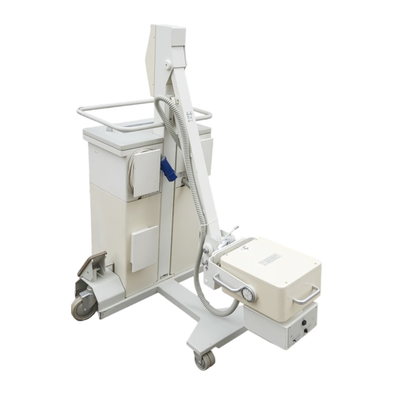
POLYMOBIL III
Start-up Instructions
from Serial No. 3000
Print No.: RXB8-115.034.02.03.02
Replaces: RXB8-115.034.02.02.02
SP
© Siemens AG 2005
The reproduction, transmission or
use of this document or its contents
is not permitted without express
written authority. Offenders will be
liable for damages. All rights,
including rights created by patent
grant or registration of a utility
model
_or_ design,_are_
reserved.
English
Doc. Gen. Date: 04.05
Advertisement
Table of Contents

Related Manuals for Siemens POLYMOBIL III


Summary of Contents for Siemens POLYMOBIL III
- Page 1 POLYMOBIL III Start-up Instructions from Serial No. 3000 © Siemens AG 2005 The reproduction, transmission or use of this document or its contents is not permitted without express written authority. Offenders will be liable for damages. All rights, including rights created by patent...
- Page 2 Assemblers and other persons who are not employed by or otherwise directly affiliated with or autho- rized by Siemens or one of its affiliates are directed to contact one of the local offices of Siemens or one of its affiliates before attempting installation or service procedures.
-
Page 3: Table Of Contents
6 _______Start-up report _________________________________________________ 6 - 1 POLYMOBIL III Start-up report ......6 - 1 7 _______Electrical safety / reports ________________________________________ 7 - 1 Protective conductor resistance / report. - Page 4 0 - 4 Contents Page This page intentionally left blank. POLYMOBIL III RXB8-115.034.02 Page 4 of 4 Siemens AG Rev. 03 04.05 CS PS 24 Medical Solutions...
-
Page 5: Emphasized Texts
This icon means "Dangerous electrical voltage". Enter the result of tests marked with this icon in the test report at the end of these instructions. Siemens AG RXB8-115.034.02 Page 1 of 8 POLYMOBIL III Medical Solutions Rev. 03 04.05 CS PS 24... -
Page 6: Required Tools And Measurement Devices
(Low kV and mAs values) - Release radiation for as short a time as possible. Checks in which radiation must be released are identified by the radiation warning symbol. POLYMOBIL III RXB8-115.034.02 Page 2 of 8 Siemens AG Rev. 03 04.05... -
Page 7: Important Start-Up Information
Install or remove components only with the generator switched off; when doing this, observe ESD guidelines. Important start-up information • The POLYMOBIL III that has been completely tested and set up in the factory is ready for use after start-up is completed. • ±... -
Page 8: Notes On The Protective Conductor Resistance Test
The values must be recorded as initial measurements in the report ’Protective conductor resistance / report’ stating the measuring points. Document the measuring procedure and the measuring instrument used (designation and serial number). POLYMOBIL III RXB8-115.034.02 Page 4 of 8 Siemens AG Rev. - Page 9 A sudden or unexpected increase of the measured values may indicate a safety-relevant defect - even if the limit value of 0.2 ohms is not exceeded (protective ground wire or contacts). Siemens AG RXB8-115.034.02 Page 5 of 8 POLYMOBIL III Medical Solutions Rev. 03 04.05 CS PS 24...
-
Page 10: Notes On Device Leakage Current Measurement
If the direct measurement of the device leakage current is used (measuring arrangement according to Fig. 3), then the system must be set up insulated during the measurement and must not be touched during the measurement. POLYMOBIL III RXB8-115.034.02 Page 6 of 8 Siemens AG Rev. - Page 11 The same measuring conditions as in the first measurement apply. Siemens AG RXB8-115.034.02 Page 7 of 8 POLYMOBIL III Medical Solutions Rev. 03 04.05 CS PS 24...
-
Page 12: Replacement For Damaged Or Lost Screws
Do not use souring powders and no organic solvents or cleaning agents, e.g. cleaning fluid, alcohol, spot remover, etc. • Water spraying is not permitted. • For further information, see the operator manual "Cleaning/Disinfecting". POLYMOBIL III RXB8-115.034.02 Page 8 of 8 Siemens AG Rev. 03 04.05... - Page 13 Place the side wall with the integrated ramp (1/Fig. 1) in front of the pallet and hook in the fastening straps. • Remove the plastic cover. Siemens AG RXB8-115.034.02 Page 1 of 2 POLYMOBIL III Medical Solutions Rev. 03 04.05 CS PS 24...
- Page 14 Remove the 2 hexagonal head screws and the bow (7/Fig. 2, width across flats 17 mm) on the left and right of the stand carriage. • Push the POLYMOBIL III over the rail (8/Fig. 3) and move it over the ramp (9/Fig. 3) away from the pallet. POLYMOBIL III RXB8-115.034.02...
-
Page 15: Checking The Nominal Line Voltage
Then close the control console in the reverse order, set it on the mobile stand, fasten it with the hand screw and connect the protective conductor cable shoe. Siemens AG RXB8-115.034.02 Page 1 of 2 POLYMOBIL III Medical Solutions Rev. 03 04.05 CS PS 24... - Page 16 3 - 2 Checking and adapting the line voltage This page intentionally left blank. POLYMOBIL III RXB8-115.034.02 Page 2 of 2 Siemens AG Rev. 03 04.05 CS PS 24 Medical Solutions...
-
Page 17: Checking The Control And Display Elements
Line voltage L i n e.g. 226 V AC display Preferred data The POLYMOBIL III is ready after the acoustic signal stops. • ± Go through the mAs values from 0.32 . . . 200 mAs by pressing the mAs buttons •... -
Page 18: Checking The Weight Counterbalance
Tighten the screw (4/Fig. 2) with a 17 mm fork wrench. Adjust the spring tension so that there is equilibrium in the horizontal support arm position, i.e. so that the forces for raising and lowering the tube assembly are the same. POLYMOBIL III RXB8-115.034.02 Page 2 of 6 Siemens AG Rev. -
Page 19: Checking The Control Elements On The Double Slot Diaphragm
• Check that the cable of the exposure release switch (9/Fig. 4) rolls back in without difficulty after it is pulled out. Siemens AG RXB8-115.034.02 Page 3 of 6 POLYMOBIL III Medical Solutions Rev. 03 04.05 CS PS 24... -
Page 20: Checking Coincidence Of Light Field And Radiation Field
• Make a note on the processed film of the following data using a waterproof felt tip pen: - SID set - Film size - Radiation field size POLYMOBIL III RXB8-115.034.02 Page 4 of 6 Siemens AG Rev. 03 04.05... - Page 21 Σ The length deviation ( Y) as well as the width deviation ( X) must be less than 1.6 cm in each case. Siemens AG RXB8-115.034.02 Page 5 of 6 POLYMOBIL III Medical Solutions Rev. 03 04.05 CS PS 24...
-
Page 22: Checking The Exposure Switch-Off
The exposure must switch off after 5 s + 3.5 s. The radiation indicator goes out, the acoustic signal stops. The exposure time depends on the level of the line voltage and NOTE the quality of the mains. POLYMOBIL III RXB8-115.034.02 Page 6 of 6 Siemens AG Rev. 03 04.05... -
Page 23: Protective Conductor Test
In the direct measurement of the device leakage current no hous- ing parts of the system may be touched during the measurement. Third-person access to the system must be prevented. Siemens AG RXB8-115.034.02 Page 1 of 2 POLYMOBIL III Medical Solutions Rev. 03 04.05 CS PS 24... -
Page 24: Reports
Wind the power connection cable onto the cable holder on the back of the control console. • Lock the support arm in the traveling position (Fig. 1) and check the forced locking of the support arm. POLYMOBIL III RXB8-115.034.02 Page 2 of 2 Siemens AG Rev. 03 04.05... -
Page 25: Polymobil Iii Start-Up Report
Start-up report 6 - 1 POLYMOBIL III Start-up report The Start-up report is arranged analogously to these Start-up instructions. Article number / type number / serial number: .... - Page 26 6 - 2 Start-up report This page intentionally left blank. POLYMOBIL III RXB8-115.034.02 Page 2 of 2 Siemens AG Rev. 03 04.05 CS PS 24 Medical Solutions...
-
Page 27: Protective Conductor Resistance / Report
Meas. inst. Ser. No.: Meas. inst. calibrated up to: n.a. Assessment: Date: Name: Signature (*1) Meas. circuit: see Fig. 1, next page Siemens AG RXB8-115.034.02 Page 1 of 6 POLYMOBIL III Medical Solutions Rev. 03 04.05 CS PS 24... - Page 28 DIN VDE 0751-1:2001-10, Fig. C2. 1 = Measuring arrangement (measuring instrument) 2 = System 3 = Application part (if present) Remarks: Date Remarks Name Signature POLYMOBIL III RXB8-115.034.02 Page 2 of 6 Siemens AG Rev. 03 04.05 CS PS 24 Medical Solutions...
-
Page 29: Device Leakage Current / Report
Meas. inst. Ser. No.: Meas. inst. calibrated up to: Assessment: Date: Name: Signature: (*1) Meas. circuit: See Fig. 2 to Fig. 3, next page Siemens AG RXB8-115.034.02 Page 3 of 6 POLYMOBIL III Medical Solutions Rev. 03 04.05 CS PS 24... - Page 30 DIN VDE 0751-1:2001-10, Fig. C6 for protective class 1 = System 2 = Application part (if present) 3 = Measuring arrangement (integrated in the measuring instrument) POLYMOBIL III RXB8-115.034.02 Page 4 of 6 Siemens AG Rev. 03 04.05...
- Page 31 Electrical safety / reports 7 - 5 Remarks: Date Remarks Name Signature Siemens AG RXB8-115.034.02 Page 5 of 6 POLYMOBIL III Medical Solutions Rev. 03 04.05 CS PS 24...
- Page 32 7 - 6 Electrical safety / reports Date Remarks Name Signature POLYMOBIL III RXB8-115.034.02 Page 6 of 6 Siemens AG Rev. 03 04.05 CS PS 24 Medical Solutions...
- Page 33 Start-up report for protective conductor test and device leakage current measurement adapted. Chapter 7 New chapter 'Electrical safety / reports' inserted. All chapters Editorial changes made. Siemens AG RXB8-115.034.02 Page 1 of 2 POLYMOBIL III Medical Solutions Rev. 03 04.05 CS PS 24...
- Page 34 8 - 2 Changes to previous version This page intentionally left blank. POLYMOBIL III RXB8-115.034.02 Page 2 of 2 Siemens AG Rev. 03 04.05 CS PS 24 Medical Solutions...