HP ProLiant BL660c Gen9 User Manual
Hide thumbs
Also See for ProLiant BL660c Gen9:
- Maintenance and service manual (80 pages) ,
- Quickspecs (38 pages)
Table of Contents
Advertisement
Quick Links
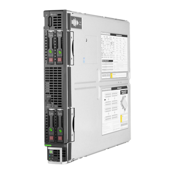
HP ProLiant BL660c Gen9 Server Blade
User Guide
Abstract
This document is for the person who installs, administers, and troubleshoots servers and storage systems. HP assumes you are qualified in the
servicing of computer equipment and trained in recognizing hazards in products with hazardous energy levels.
Part Number: 798293-001
June 2015
Edition: 1
Advertisement
Table of Contents

Related Manuals for HP ProLiant BL660c Gen9


Summary of Contents for HP ProLiant BL660c Gen9
- Page 1 User Guide Abstract This document is for the person who installs, administers, and troubleshoots servers and storage systems. HP assumes you are qualified in the servicing of computer equipment and trained in recognizing hazards in products with hazardous energy levels.
- Page 2 © Copyright 2015 Hewlett-Packard Development Company, L.P. The information contained herein is subject to change without notice. The only warranties for HP products and services are set forth in the express warranty statements accompanying such products and services. Nothing herein should be construed as constituting an additional warranty. HP shall not be liable for technical or editorial errors or omissions contained herein.
-
Page 3: Table Of Contents
Install the storage controller ........................20 Install the access panel..........................22 Setup ............................23 Installing an HP BladeSystem c-Class enclosure ................... 23 Preparing the enclosure ........................23 Installing interconnect modules ........................26 Interconnect bay numbering and device mapping ................27 Connecting to the network ........................ - Page 4 Direct connect SATA cabling ........................60 SAS cabling ............................61 Using the HP c-Class Blade SUV Cable ...................... 61 Connecting locally to a server blade with video and USB devices ..............61 Accessing a server blade with local KVM ..................61 Accessing local media devices ......................
- Page 5 Software and firmware ........................77 Operating System Version Support ....................77 Version control ..........................77 HP operating systems and virtualization software support for ProLiant servers ........78 HP Technology Service Portfolio ...................... 78 Change control and proactive notification ..................78 Troubleshooting ..........................
-
Page 6: Component Identification
Drive Bay 3 Drive Bay 4 Server blade release lever Server blade release button *The SUV connector and the HP c-Class Blade SUV Cable are used for some server blade configuration and diagnostic procedures. Front panel LEDs and buttons Item Description... -
Page 7: Power Fault Leds
3 flashes Memory 4 flashes Riser board PCIe slots 5 flashes FlexibleLOM 6 flashes Removable HP Flexible Smart Array controller/Smart SAS HBA controller 7 flashes System board PCIe slots 8 flashes Power backplane or storage backplane 9 flashes Power supply... -
Page 8: Hot-Plug Drive Led Definitions
Item Description Drive bay 1 Drive bay 2 Drive bay 3 Drive bay 4 Hot-plug drive LED definitions Item Status Definition Locate Solid blue The drive is being identified by a host application. Flashing blue The drive carrier firmware is being updated or requires an update. Activity ring Rotating green Drive activity... -
Page 9: System Board Components
System board components Item Description Solid state device connector (M.2) HP Smart Storage Battery connector Processor 3 DIMM slots (8) Processor 3 SAS controller connector Processor 1 DIMM slots (8) Processor 1 Board mounting screws (3) Enclosure connectors (2) Mezzanine connector 1 (Type A mezzanine only) -
Page 10: System Maintenance Switch
The symbols correspond to the symbols located on the interconnect bays. For more information, see the HP ProLiant BL660c Gen9 Server Blade Installation Instructions on the HP website (http://www.hp.com/support). System maintenance switch Position Default Function Off = iLO security is enabled. -
Page 11: Dimm Slot Locations
DIMM slots are numbered sequentially (1 through 8) for each processor. The supported AMP modes use the alpha assignments for population order, and the slot numbers designate the DIMM slot ID for spare replacement. HP c-Class Blade SUV Cable Item Connector... -
Page 12: Operations
For more information about the Onboard Administrator, see the enclosure setup and installation guide on the HP website (http://www.hp.com/support/oa). For more information about iLO, see "HP iLO (on page 64)." Power down the server blade Before powering down the server blade for any upgrade or maintenance procedures, perform a backup of critical server data and programs. -
Page 13: Remove The Server Blade
poweroff server [bay number] force This form of the command forces the server blade to enter standby mode without properly exiting applications and the OS. If an application stops responding, this method forces a shutdown. • Use the Onboard Administrator GUI to initiate a shutdown: Select the Enclosure Information tab. -
Page 14: Remove The Access Panel
Remove the access panel To remove the component: Power down the server blade (on page 12). Remove the server blade (on page 13). Place the server blade on a flat, level work surface. Press the access panel release button. Slide the access panel towards the rear of the server blade, and then lift to remove the panel. Remove a hard drive blank Remove the component as indicated. -
Page 15: Remove The Center Dimm Baffle
Disconnect any cables that may be routed across the DIMM baffle. IMPORTANT: When removing the left DIMM baffle, leave the HP Smart Storage Battery installed on the baffle. Use the blue pull tab to disconnect the HP Smart Storage Battery cable from the system board. Operations 15... -
Page 16: Remove The Right Dimm Baffle
Remove the left DIMM baffle. Remove the right DIMM baffle To remove the component: Power down the server blade (on page 12). Remove the server blade (on page 13). Place the server blade on a flat, level work surface. Remove the access panel (on page 14). Disconnect any cables that may be routed across the DIMM baffle. -
Page 17: Remove The Storage Controller
Remove the storage controller Power down the server blade (on page 12). Remove the server blade (on page 13). Place the server blade on a flat, level work surface. Remove the access panel (on page 14). Disconnect the SAS cable from the storage controller and the drive backplane. Prepare the storage controller for removal. -
Page 18: Remove The Front Panel/Drive Cage Assembly
Remove the storage controller. Remove the front panel/drive cage assembly Power down the server blade (on page 12). Remove the server blade (on page 13). Place the server blade on a flat, level work surface. Remove the access panel (on page 14). Do one of the following: Remove the storage controller (on page 17). -
Page 19: Remove The Mezzanine Assembly
Extend the serial label pull tab. Remove the front panel/drive cage assembly. Remove the mezzanine assembly Power down the server blade (on page 12). Remove the server blade (on page 13). Place the server blade on a flat, level work surface. Remove the access panel (on page 14). -
Page 20: Remove The Flexiblelom
Remove the mezzanine assembly. Remove the FlexibleLOM Power down the server blade (on page 12). Remove the server blade (on page 13). Place the server blade on a flat, level work surface. Remove the access panel (on page 14). Remove the mezzanine assembly (on page 19). Use the FlexibleLOM handle to remove the FlexibleLOM from the system board.