
Related Manuals for GE Vivid 7


Summary of Contents for GE Vivid 7
- Page 1 GE Healthcare Vivid 7 Service Manual Operating Documentation Part Number: FC091194 Revision: 11...
- Page 3 • VERSUCHEN SIE NICHT, DAS GERÄT ZU REPARIEREN, BEVOR DIESES WARNUNG KUNDENDIENST-HANDBUCH NICHT ZU RATE GEZOGEN UND VERSTANDEN (DE) WURDE. • WIRD DIESE WARNUNG NICHT BEACHTET, SO KANN ES ZU VERLETZUNGEN DES KUNDENDIENSTTECHNIKERS, DES BEDIENERS ODER DES PATIENTEN DURCH ELEKTRISCHE SCHLÄGE, MECHANISCHE ODER SONSTIGE GEFAHREN KOMMEN.
- Page 4 GE H EALTHCARE FC091194, R IRECTION EVISION IVID ERVICE ANUAL • ESTE MANUAL DE SERVICIO SÓLO EXISTE EN INGLÉS. • SI ALGÚN PROVEEDOR DE SERVICIOS AJENO A GEHC SOLICITA UN IDIOMA QUE NO SEA EL INGLÉS, ES RESPONSABILIDAD DEL CLIENTE OFRECER UN SERVICIO DE TRADUCCIÓN.
- Page 5 ΣΤΟΝ ΑΣΘΕΝΗ ΑΠΟ ΗΛΕΚΤΡΟΠΛΗΞΙΑ, ΜΗΧΑΝΙΚΟΥΣ Ή ΑΛΛΟΥΣ ΚΙΝΔΥΝΟΥΣ. • EZEN KARBANTARTÁSI KÉZIKÖNYV KIZÁRÓLAG ANGOL NYELVEN ÉRHETŐ • HA A VEVŐ SZOLGÁLTATÓJA ANGOLTÓL ELTÉRŐ NYELVRE TART IGÉNYT, AKKOR A VEVŐ FELELŐSSÉGE A FORDÍTÁS ELKÉSZÍTTETÉSE. • NE PRÓBÁLJA ELKEZDENI HASZNÁLNI A BERENDEZÉST, AMÍG A FIGYELMEZTETÉS KARBANTARTÁSI KÉZIKÖNYVBEN LEÍRTAKAT NEM ÉRTELMEZTÉK.
- Page 6 GE H EALTHCARE FC091194, R IRECTION EVISION IVID ERVICE ANUAL • TENTO SERVISNÍ NÁVOD EXISTUJE POUZE V ANGLICKÉM JAZYCE. • V PŘÍPADĚ, ŽE POSKYTOVATEL SLUŽEB ZÁKAZNÍKŮM POTŘEBUJE NÁVOD V JINÉM JAZYCE, JE ZAJIŠTĚNÍ PŘEKLADU DO ODPOVÍDAJÍCÍHO JAZYKA ÚKOLEM ZÁKAZNÍKA. • NEPROVÁDĚJTE ÚDRŽBU TOHOTO ZAŘÍZENÍ, ANIŽ BYSTE SI PŘEČETLI TENTO SERVISNÍ...
- Page 7 GE H EALTHCARE FC091194, R IRECTION EVISION IVID ERVICE ANUAL • ŠIS EKSPLOATAVIMO VADOVAS YRA IŠLEISTAS TIK ANGLŲ KALBA. • JEI KLIENTO PASLAUGŲ TEIKĖJUI REIKIA VADOVO KITA KALBA – NE ANGLŲ, VERTIMU PASIRŪPINTI TURI KLIENTAS. • NEMĖGINKITE ATLIKTI ĮRANGOS TECHNINĖS PRIEŽIŪROS DARBŲ, NEBENT ĮSPĖJIMAS...
- Page 8 GE H EALTHCARE FC091194, R IRECTION EVISION IVID ERVICE ANUAL • ДАННОЕ РУКОВОДСТВО ПО ОБСЛУЖИВАНИЮ ПРЕДОСТАВЛЯЕТСЯ ТОЛЬКО НА АНГЛИЙСКОМ ЯЗЫКЕ. • ЕСЛИ СЕРВИСНОМУ ПЕРСОНАЛУ КЛИЕНТА НЕОБХОДИМО РУКОВОДСТВО НЕ НА АНГЛИЙСКОМ ЯЗЫКЕ, КЛИЕНТУ СЛЕДУЕТ САМОСТОЯТЕЛЬНО ОБЕСПЕЧИТЬ ПЕРЕВОД. • ПЕРЕД ОБСЛУЖИВАНИЕМ ОБОРУДОВАНИЯ ОБЯЗАТЕЛЬНО ОБРАТИТЕСЬ...
- Page 9 GE H EALTHCARE FC091194, R IRECTION EVISION IVID ERVICE ANUAL (JA) (ZH-CN) (KO)
- Page 10 GE Healthcare personnel. In performing all electrical work on these products, GE will use its own specially trained field engineers. All of GE’s electrical work on these products will comply with the requirements of the applicable electrical codes.
- Page 11 The contents of this publication may not be copied or duplicated in any form, in whole or in part, without prior written permission of GE Healthcare. GE Healthcare may revise this publication from time to time without written notice. TRADEMARKS All products and their name brands are trademarks of their respective holders.
- Page 12 ANUAL Revision History REVISION DATE REASON FOR CHANGE Covers both Vivid 7 and Vivid 7 PRO 11. JUN. 2002 Replaces Vivid 7 Service Manual, Part Number FB091202 30. AUG. 2002 Updated per BT02-M4 release. Included description for BEP-2. 6. JUN. 2003 Updated per BT03-M3 release (software version V 3.0.x).
-
Page 13: Table Of Contents
Label on Rear Cover - Vivid 7 Dimension for China ....1 - 34 Label on Rear Cover - Vivid 7 for China ......1 - 38 Label on Rear Cover - Vivid 7 PRO for China . - Page 14 Label on Rear Cover - Vivid 7 Dimension for Korea ....1 - 43 Label on Rear Cover - Vivid 7 PRO for Korea ..... . . 1 - 44 Label on Rear Cover - Vivid 7 - Details Descriptions .
- Page 15 GE H EALTHCARE FC091194, R IRECTION EVISION IVID ERVICE ANUAL CHAPTER 2 Site Preparations Overview............2 - 1 Purpose of Chapter 2 .
- Page 16 Vivid 7 Configuration ........
- Page 17 Query/Retrieve (Q/R) Setup for Software v7.x/v6.x/v5.x/v4.x ... 3 - 78 Mapping of Parameters from Vivid 7 to DICOM ..... 3 - 85 Connectivity Setup - Software v3.x.
- Page 18 GE H EALTHCARE FC091194, R IRECTION EVISION IVID ERVICE ANUAL HL7 Communication Setup for Software v2.x ..... . . 3 - 122 Set Up Connection to a DICOM Server in a Network - Software v2.x .
- Page 19 Backup - Software Version v7.x/v6.x/v5.x/v4.x ..... . 4 - 23 Moving and Transporting the Vivid 7 ......4 - 26 Functional Checks .
- Page 20 GE H EALTHCARE FC091194, R IRECTION EVISION IVID ERVICE ANUAL Back-End Processor Checks ........4 - 73 Peripheral Checks .
- Page 21 GE H EALTHCARE FC091194, R IRECTION EVISION IVID ERVICE ANUAL CHAPTER 5 Components and Functions (Theory) Overview............5 - 1 Purpose of Chapter 5 .
- Page 22 GE H EALTHCARE FC091194, R IRECTION EVISION IVID ERVICE ANUAL Introduction ..........5 - 74 Signal Flow and Processing .
- Page 23 Location in the Unit Vivid 7 PRO ....... .
- Page 24 Restart Vivid 7 After Diagnostics ....... . .
- Page 25 GE H EALTHCARE FC091194, R IRECTION EVISION IVID ERVICE ANUAL CHAPTER 6 Service Adjustments Overview............6 - 1 Purpose of this Chapter .
- Page 26 GE H EALTHCARE FC091194, R IRECTION EVISION IVID ERVICE ANUAL CHAPTER 7 Diagnostics/Troubleshooting Overview ............7 - 1 Purpose of this Chapter .
- Page 27 GE H EALTHCARE FC091194, R IRECTION EVISION IVID ERVICE ANUAL Calibration Screen ......... . . 7 - 64 System Test .
- Page 28 GE H EALTHCARE FC091194, R IRECTION EVISION IVID ERVICE ANUAL CHAPTER 8 Replacement Procedures Overview ............8 - 1 Purpose of Chapter 8 .
- Page 29 GE H EALTHCARE FC091194, R IRECTION EVISION IVID ERVICE ANUAL Lower Rear Cover Removal Procedure ......8 - 10 Lower Rear Cover Installation Procedure .
- Page 30 GE H EALTHCARE FC091194, R IRECTION EVISION IVID ERVICE ANUAL Prepare MO Disks for Image Storage - Software Version v2.x ..8 - 56 Move Images - Software Version v2.x ......8 - 57 Prepare MO Disk for Patient Archive - Software Version v2.x .
- Page 31 GE H EALTHCARE FC091194, R IRECTION EVISION IVID ERVICE ANUAL Rear Casters Replacement Procedure........8 - 91 Manpower .
- Page 32 Introduction ..........9 - 22 Console Lock - VIVID 7/VIVID 7 Dimension ......9 - 23 Console Lock - Vivid 7 PRO .
- Page 33 GE H EALTHCARE FC091194, R IRECTION EVISION IVID ERVICE ANUAL Operator Panel–Version 3 ........9 - 28 Operator Panel–Version 2 .
- Page 34 Accessory Boxes, Vivid 7 / Vivid 7 PRO ....... . .
- Page 35 Product Manuals for Units with Software Version v2.x ....9 - 119 Packing Parts for Reshipment - Vivid 7 with LCD ......9 - 120 Packing Parts for Reshipment - Vivid 7 with CRT .
- Page 36 GE H EALTHCARE FC091194, R IRECTION EVISION IVID ERVICE ANUAL CHAPTER 10 Care & Maintenance Overview ............10 - 1 Periodic Maintenance Inspections .
- Page 37 GE H EALTHCARE FC091194, R IRECTION EVISION IVID ERVICE ANUAL Site Log ............10 - 27 Index .
- Page 38 GE H EALTHCARE FC091194, R IRECTION EVISION IVID ERVICE ANUAL - xxxvi...
-
Page 39: Overview
Returning/Shipping Probes and Repair Parts 1-70 Electromagnetic Compatibility (EMC) 1-10 1-71 Customer Assistance 1-1-3 Purpose of Service Manual This Service Manual provides installation and service information for the Vivid 7 Ultrasound Scanning unit. Chapter 1 - Introduction 1 - 1... - Page 40 Contents in this Service Manual The service manual is divided in ten chapters. In the beginning of the manual, before chapter 1, you will find the language policy for GE Healthcare’s service documentation, legal information, a revision overview and the Table of Contents (TOC).
- Page 41 VIVID 7 DIMENSION CONSOLE, LCD MONITOR, 100-120 VAC FD000120 VIVID 7 PRO CONSOLE, LCD MONITOR, 230 VAC FD000130 VIVID 7 PRO CONSOLE, LCD MONITOR, 100-120 VAC FD000140 VIVID 7 DIM. W/ MULTI-DIM. & VOLUME, LCD MONITOR, 230 VAC FEP2 BEP4.2 v7.0 (RFI) FD000150 VIVID 7 DIM.
- Page 42 GE H EALTHCARE FC091194, R IRECTION EVISION IVID ERVICE ANUAL Table 1-3 Vivid 7 Models and Hardware/Software Compatibility (cont’d) sheet 2 of 3 APPLICATION MODEL FRONT-END BACK-END SOFTWARE NUMBER DESCRIPTION PROCESSOR PROCESSOR VERSION(S) VIVID 7 DIMENSION, MULTIDIMENSIONAL RENDERING AND VOLUME FC000760 (BT’05), 230 VAC...
- Page 43 VIVID 7 (BT’01), 100 - 120 VAC with BEP1 FC000030 VIVID 7 (BT’01), 230 VAC - BEP2 may be used as FRU NOTE: When not otherwise specified, the contents in this manual applies to all Vivid 7 models. Chapter 1 - Introduction 1 - 5...
-
Page 44: Product Description
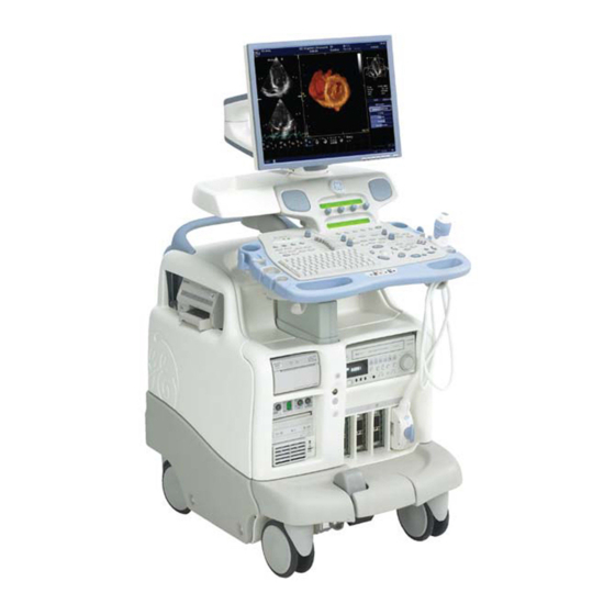
Real Time 3D measurements (4D) • Vivid 7 is a digital beam forming unit and can handle up to 192 element linear probes by use of multiplexing. • Signal flow from the Probe Connector Panel to the Front-End, then to the Mid Processors and Back- End Processor and finally to the monitor and peripherals. - Page 45 GE H EALTHCARE FC091194, R IRECTION EVISION IVID ERVICE ANUAL 1-2-4-1 Overview of the Vivid 7 Ultrasound Scanner (cont’d) CRT MONITOR. (Discontinued 2007) 21” LCD MONITOR - STANDARD FOR BT’08. - OPTION FOR BT’06 UPPER PANEL WITH STEREO LOUDSPEAKERS OPERATOR PANEL...
- Page 46 1-2-4-8 Purpose of Operator Manual(s) The Operator Manual(s) should be fully read and understood before operating the Vivid 7 and also kept near the unit for quick reference. 1 - 8 Section 1-2 - Service Manual Overview...
-
Page 47: Important Conventions
Important Conventions 1-3-1 Conventions Used in Book 1-3-1-1 Model Designations. This manual covers the Vivid 7 scanners listed in Table 1-3 on page 1-3. 1-3-1-2 Icons Pictures, or icons, are used wherever they will reinforce the printed message. The icons, labels and conventions used on the product and in the service information are described in this chapter. -
Page 48: Standard Hazard Icons
GE H EALTHCARE FC091194, R IRECTION EVISION IVID ERVICE ANUAL 1-3-2 Standard Hazard Icons Important information will always be preceded by the exclamation point contained within a triangle, as seen throughout this chapter. In addition to text, several different graphical icons (symbols) may be used to make you aware of specific types of hazards that could possibly cause harm. -
Page 49: Product Icons
IPX8 indicates drip proof and may be IP Code (IPX8/IP68) Footswitch used in an Operating Theater. The footswitch delivered with Vivid 7 is IP68 rated. Equipment Type BF (man in the box Probe connectors including Doppler symbol) IEC 878-02-03 indicates B... - Page 50 Vivid 7 SCANNERS PRODUCED “TESTED AND PRODUCTION AFTER SEPTEMBER 2004: MONITORED BY TUV PRODUCT SERVICE NRTL WITH RESPECT TO REAR OF CONSOLE ON Vivid 7 ELECTRICAL SHOCK, FIRE AND PRODUCED AFTER SEPTEMBER MECHANICAL HAZARDS ONLY IN 2004 ACCORDANCE WITH UL2601-1 AND CAN/CSA C22.2 NO.601.1”...
- Page 51 GE H EALTHCARE FC091194, R IRECTION EVISION IVID ERVICE ANUAL Table 1-6 Product Icons (cont’d) sheet 3 of 4 LABEL/SYMBOL PURPOSE/MEANING LOCATION “CAUTION - Dangerous voltage” (the lightning flash with arrowhead in Various equilateral triangle) is used to indicate electric shock hazards.
- Page 52 GE H EALTHCARE FC091194, R IRECTION EVISION IVID ERVICE ANUAL Table 1-6 Product Icons (cont’d) sheet 4 of 4 LABEL/SYMBOL PURPOSE/MEANING LOCATION The following product pollution control information is provided according to SJ/T11364-2006 Marking for Control of Pollution caused by Electronic Information Products.
-
Page 53: Safety Considerations
GE H EALTHCARE FC091194, R IRECTION EVISION IVID ERVICE ANUAL Section 1-4 Safety Considerations 1-4-1 Overview Table 1-7 Contents in Section 1-4 - Safety Considerations SUB- SECTION DESCRIPTION PAGE NUMBER 1-4-1 1-15 Overview 1-4-2 1-15 Introduction 1-4-3 1-16 Human Safety... -
Page 54: Human Safety
Operating personnel must not remove the system covers. Servicing should be performed by authorized personnel only. Only personnel who have participated in a Vivid 7 Training are authorized to service the equipment. 1 - 16 Section 1-4 - Safety Considerations... -
Page 55: Mechanical Safety
Keep the heat venting holes on the monitor unobstructed to avoid overheating of the monitor. CAUTION VIVID 7 weighs 190 kg (419 lbs) or more, depending on installed peripherals, when ready for use. CAUTION Care must be used when moving it or replacing its parts. Failure to follow the precautions listed below could result in injury, uncontrolled motion and costly damage. - Page 56 CAUTION before moving the monitor and the monitor arm. This includes people as well as things. Do not transport Vivid 7 in a vehicle without locking the casters (wheels). CAUTION Use all Personal Protection Equipment (PPE) such as gloves, safety shoes, safety glasses, and CAUTION kneeling pad, to reduce the risk of injury.
-
Page 57: Electrical Safety
• Both the system power cable and the power connector must meet international electrical standards. WARNING WARNING CONNECTING A Vivid 7 SCANNER TO THE WRONG VOLTAGE LEVEL WILL MOST LIKELY DESTROY IT. 1-4-5-2 Probes Follow these guidelines before connecting a probe to the scanner;... -
Page 58: Labels Locations
Label, Vivid 7 (Monitor) (Introduced in 2002) Label, Vivid 7 PRO (Monitor) (Introduced in 2002) Label, Vivid 7 Dimension (Monitor) (Introduced 2004) For Vivid 7 Dimension with LCD screen (option since 2006) 1 - 20 Section 1-5 - Labels Locations... - Page 59 ERVICE ANUAL Table 1-8 Labels on Front of Monitor and Operator Panel (cont’d) DESCRIPTION ILLUSTRATION Label, GE Logo press once ON/OFF: FC314104 03 Label, On/Off Switch (Two versions of the label have been used, the one to the right is the latest version.)
-
Page 60: Labels On Rear Of Lcd Monitor
GE H EALTHCARE FC091194, R IRECTION EVISION IVID ERVICE ANUAL 1-5-2 Labels on Rear of LCD Monitor Table 1-9 Label on Rear of LCD Monitor DESCRIPTION ILLUSTRATION Firmware label LCD monitor FOR USA ONLY: LCD MONITOR MERCURY HG. Introduced October 1, 2007... -
Page 61: Labels On Front Handle
GE H EALTHCARE FC091194, R IRECTION EVISION IVID ERVICE ANUAL 1-5-3 Labels on Front Handle Table 1-10 Labels on Front Handle DESCRIPTION ILLUSTRATION Label, Front Handle Three versions of the label have been used. The lower one is the latest version. -
Page 62: Labels Near Connectors On Front
GE H EALTHCARE FC091194, R IRECTION EVISION IVID ERVICE ANUAL 1-5-4 Labels Near Connectors on Front Table 1-11 Labels Near Connectors on Front Description Illustration Label, Probe Connector (The Label, “Probe Connector” consists of three labels, named; - “Main Label Part”, - “Heart Symbol”... -
Page 63: Label On External I/O
GE H EALTHCARE FC091194, R IRECTION EVISION IVID ERVICE ANUAL 1-5-5 Label on External I/O Table 1-12 Label, External I/O DESCRIPTION ILLUSTRATION Marking introduced late 2002. (Not In Use) Label, External. I/O Chapter 1 - Introduction 1 - 25... -
Page 64: Labels At Ac Mains Inlet And Circuit Breaker
V i v i d 7 P r o d u c t n a m e : Since the introduction of the Vivid 7, the Serial Number have been changed a few times: - On the first systems (with RFT), the serial number were a 4 digit serial number. - Page 65 GE H EALTHCARE FC091194, R IRECTION EVISION IVID ERVICE ANUAL Table 1-13 Labels at AC Mains Inlet and Circuit Breaker (used before May 2002) (cont’d) DESCRIPTION ILLUSTRATION Ground (GND) Label. (Used on 230 VAC Systems and some 100-120 VAC Systems.)
-
Page 66: Label On Rear Cover - Vivid 7 Dimension
ERVICE ANUAL 1-5-7 Label on Rear Cover - Vivid 7 Dimension Table 1-15 Label on Rear Cover - Vivid 7 Dimension sheet 1 of 2 DESCRIPTION ILLUSTRATION Label, General Info (Located on rear of system) Label used for Vivid 7 Dimension after OCT. 2005... -
Page 67: Label On Rear Cover - Vivid 7
FC091194, R IRECTION EVISION IVID ERVICE ANUAL Table 1-15 Label on Rear Cover - Vivid 7 Dimension (cont’d) sheet 2 of 2 DESCRIPTION ILLUSTRATION Label, General Info (Located on rear of system) Label used for Vivid 7 Dimension Label, General Info... - Page 68 IVID ERVICE ANUAL 1-5-8 Label on Rear Cover - Vivid 7 Table 1-16 Label on Rear Cover - Vivid 7 sheet 1 of 2 DESCRIPTION ILLUSTRATION Label, General Info (Located on rear of system) Label used for Vivid 7 after JUNY 2005...
- Page 69 IRECTION EVISION IVID ERVICE ANUAL Table 1-16 Label on Rear Cover - Vivid 7 (cont’d) sheet 2 of 2 DESCRIPTION ILLUSTRATION Label, General Info (Located on rear of system) Label used for Vivid 7 between 2 May 2002 and September 2004.
-
Page 70: Label On Rear Cover - Vivid 7 Pro
ERVICE ANUAL 1-5-9 Label on Rear Cover - Vivid 7 PRO Table 1-17 Label on Rear Cover - Vivid 7 PRO sheet 1 of 2 DESCRIPTION ILLUSTRATION Label, General Info (Located on rear of system) Label used for Vivid 7 PRO... - Page 71 FC091194, R IRECTION EVISION IVID ERVICE ANUAL Table 1-17 Label on Rear Cover - Vivid 7 PRO (cont’d) sheet 2 of 2 DESCRIPTION ILLUSTRATION Label, General Info (Located on rear of system) Label used for Vivid 7 PRO introduced September 2004...
-
Page 72: Label On Rear Cover - Vivid 7 Dimension For China
ERVICE ANUAL 1-5-10 Label on Rear Cover - Vivid 7 Dimension for China Table 1-18 Label on Rear Cover - Vivid 7 Dimension for China sheet 1 of 4 DESCRIPTION ILLUSTRATION Label, General Info (Located on rear of system) Label used for Vivid 7 to China... - Page 73 IRECTION EVISION IVID ERVICE ANUAL Table 1-18 Label on Rear Cover - Vivid 7 Dimension for China (cont’d) sheet 2 of 4 DESCRIPTION ILLUSTRATION Label, General Info (Located on rear of system) Label used for Vivid 7 to China introduced OCTOBER 2005...
- Page 74 IRECTION EVISION IVID ERVICE ANUAL Table 1-18 Label on Rear Cover - Vivid 7 Dimension for China (cont’d) sheet 3 of 4 DESCRIPTION ILLUSTRATION Label, General Info (Located on rear of system) Label used for Vivid 7 to China introduced JUNE 2005...
- Page 75 IRECTION EVISION IVID ERVICE ANUAL Table 1-18 Label on Rear Cover - Vivid 7 Dimension for China (cont’d) sheet 4 of 4 DESCRIPTION ILLUSTRATION Label, General Info (Located on rear of system) Label used for Vivid 7 to China introduced September 2004...
-
Page 76: Label On Rear Cover - Vivid 7 For China
FC091194, R IRECTION EVISION IVID ERVICE ANUAL 1-5-11 Label on Rear Cover - Vivid 7 for China Table 1-19 Label on Rear Cover - Vivid 7 for China DESCRIPTION ILLUSTRATION Label, General Info (Located on rear of system) Label used for Vivid 7 before 2 May 2002... -
Page 77: Label On Rear Cover - Vivid 7 Pro For China
ERVICE ANUAL 1-5-12 Label on Rear Cover - Vivid 7 PRO for China Table 1-20 Label on Rear Cover - Vivid 7 PRO for China sheet 1 of 4 DESCRIPTION ILLUSTRATION Label, General Info (Located on rear of system) Label used for Vivid 7 PRO to China... - Page 78 IRECTION EVISION IVID ERVICE ANUAL Table 1-20 Label on Rear Cover - Vivid 7 PRO for China (cont’d) sheet 2 of 4 DESCRIPTION ILLUSTRATION Label, General Info (Located on rear of system) Label used for Vivid 7 PRO to China...
- Page 79 IRECTION EVISION IVID ERVICE ANUAL Table 1-20 Label on Rear Cover - Vivid 7 PRO for China (cont’d) sheet 3 of 4 DESCRIPTION ILLUSTRATION Label, General Info (Located on rear of system) Label used for Vivid 7 PRO to China...
- Page 80 IRECTION EVISION IVID ERVICE ANUAL Table 1-20 Label on Rear Cover - Vivid 7 PRO for China (cont’d) sheet 4 of 4 DESCRIPTION ILLUSTRATION Label, General Info (Located on rear of system) Label used for Vivid 7 PRO to China...
-
Page 81: Label On Rear Cover - Vivid 7 Dimension For Korea
FC091194, R IRECTION EVISION IVID ERVICE ANUAL 1-5-13 Label on Rear Cover - Vivid 7 Dimension for Korea Table 1-21 Label on Rear Cover - Vivid 7 Dimension for Korea DESCRIPTION ILLUSTRATION Label, General Info (Located on rear of system) Label used for Vivid 7 Dimension after DEC. -
Page 82: Label On Rear Cover - Vivid 7 Pro For Korea
FC091194, R IRECTION EVISION IVID ERVICE ANUAL 1-5-14 Label on Rear Cover - Vivid 7 PRO for Korea Table 1-22 Label on Rear Cover - Vivid 7 PRO for Korea DESCRIPTION ILLUSTRATION Label, General Info (Located on rear of system) Label used for Vivid 7 Dimension after DEC. -
Page 83: Label On Rear Cover - Vivid 7 - Details Descriptions
ERVICE ANUAL 1-5-15 Label on Rear Cover - Vivid 7 - Details Descriptions Table 1-23 Label on Rear Cover - Vivid 7, Details Descriptions sheet 1 of 2 DESCRIPTION ILLUSTRATION Label on rear side of the Vivid 7. CLASS I... - Page 84 IRECTION EVISION IVID ERVICE ANUAL Table 1-23 Label on Rear Cover - Vivid 7, Details Descriptions (cont’d) sheet 2 of 2 DESCRIPTION ILLUSTRATION Vivid 7 SCANNERS PRODUCED AFTER SEPTEMBER 2004: “TESTED AND PRODUCTION Vivid 7 SCANNERS PRODUCED AFTER SEPTEMBER 2004:...
-
Page 85: Labels On Internal I/O (Inside Scanner)
GE H EALTHCARE FC091194, R IRECTION EVISION IVID ERVICE ANUAL 1-5-16 Labels on Internal I/O (Inside Scanner) Label on Front-End Card Cage Side of Internal I/O Figure 1-2 Labels on Internal I/O (Inside Scanner), Front-End Card Cage Side of Internal I/O... - Page 86 GE H EALTHCARE FC091194, R IRECTION EVISION IVID ERVICE ANUAL 1-5-17 Labels on Internal I/O (Inside Scanner) Label on Back-End Processor Side of Internal I/O Figure 1-3 Labels on Internal I/O (Inside Scanner), Back-End Processor Side of Internal I/O 1 - 48...
- Page 87 GE H EALTHCARE FC091194, R IRECTION EVISION IVID ERVICE ANUAL 1-5-17 Labels on Internal I/O (Inside Scanner) (cont’d) Connectors to/from Back End From Back BW printer video, printer remote control VCR remote control (RS232) Spare RS232 Signals & power to/from top console...
- Page 88 GE H EALTHCARE FC091194, R IRECTION EVISION IVID ERVICE ANUAL 1-5-17 Labels on Internal I/O (Inside Scanner) (cont’d) NOTE: On units with RFI ONLY: A11 has been moved from the Internal I/O module to the BEP. Figure 1-5 Label on Internal I/O on units with BEP2.2, BEP3 and BEP3.2...
-
Page 89: Label, Internal Connections (Int.conn.)
ANUAL 1-5-18 Label, Internal Connections (Int.Conn.) Located on the outside of the Front-End Card Rack (FEP1) Cover (inside Vivid 7). Different versions of the label have been used since production start. Cable and Connector numbering and naming system used: Distribution... -
Page 90: Label, Internal Connections (Int.conn.)
GE H EALTHCARE FC091194, R IRECTION EVISION IVID ERVICE ANUAL 1-5-19 Label, Internal Connections (Int.Conn.) Located on the outside of the Front-End Card Rack’s cover (inside unit). Different versions of the label have been used since production start. Cable and Connector numbering and naming system used:... -
Page 91: Label, Bep1, Internal Connections (Int.conn.)
GE H EALTHCARE FC091194, R IRECTION EVISION IVID ERVICE ANUAL 1-5-20 Label, BEP1, Internal Connections (Int.Conn.) Located on the outside of the Back-End Processor’s Cover (inside unit) Figure 1-8 Label on BEP1, Internal Connections (Int.Conn.) Chapter 1 - Introduction 1 - 53... -
Page 92: Label, Bep2, Internal Connections (Int.conn.)
GE H EALTHCARE FC091194, R IRECTION EVISION IVID ERVICE ANUAL 1-5-21 Label, BEP2, Internal Connections (Int.Conn.) Located on the outside of the Back-End Processor’s Cover (inside unit) Power for i/o boards - to B6 Signals to i/o boards - to B5... -
Page 93: Label, Bep4 As Bep2 Replacement, Internal Connections (Int.conn.)
ERVICE ANUAL 1-5-22 Label, BEP4 as BEP2 Replacement, Internal Connections (Int.Conn.) Located on the outside of the Back-End Processor’s Cover (inside Vivid 7) Figure 1-11 Label, BEP4 as BEP2 Replacement, Internal Connections (Int.Conn.) Chapter 1 - Introduction 1 - 55... -
Page 94: Label, Bep2.2, Internal Connections (Int.conn.)
GE H EALTHCARE FC091194, R IRECTION EVISION IVID ERVICE ANUAL 1-5-23 Label, BEP2.2, Internal Connections (Int.Conn.) Located on the outside of the Back-End Processor’s Cover (inside unit) Power for i/o boards - to B6 Signals to i/o boards - to B5... -
Page 95: Label, Bep4 As Bep2.2 Replacement, Internal Connections (Int.conn.)
ANUAL 1-5-24 Label, BEP4 as BEP2.2 Replacement, Internal Connections (Int.Conn.) Located on the outside of the Back-End Processor’s Cover (inside Vivid 7) Figure 1-13 Label, BEP4 as BEP 2-2 replacement, Internal Connections (Int.Conn.) Chapter 1 - Introduction 1 - 57... -
Page 96: Label, Bep3.X, Internal Connections (Int.conn.)
GE H EALTHCARE FC091194, R IRECTION EVISION IVID ERVICE ANUAL 1-5-25 Label, BEP3.x, Internal Connections (Int.Conn.) Located on the outside of the Back-End Processor’s Cover (inside unit). Figure 1-14 Label, BEP3.x, Internal Connections (Int.Conn.) 1 - 58 Section 1-5 - Labels Locations... -
Page 97: Label, Bep3.X With 4D, Internal Connections (Int.conn.)
GE H EALTHCARE FC091194, R IRECTION EVISION IVID ERVICE ANUAL 1-5-26 Label, BEP3.x with 4D, Internal Connections (Int.Conn.) Located on the outside of the Back-End Processor’s Cover (inside unit). Figure 1-15 Label, BEP3.x with 4D, Internal Connections (Int.Conn.) Chapter 1 - Introduction... -
Page 98: Label, Bep4.X, Internal Connections (Int.conn.)
FC091194, R IRECTION EVISION IVID ERVICE ANUAL 1-5-27 Label, BEP4.x, Internal Connections (Int.Conn.) Located on the outside of the Back-End Processor’s Cover (inside Vivid 7) Figure 1-16 Label, BEP4.x, Internal Connections (Int.Conn.) 1 - 60 Section 1-5 - Labels Locations... -
Page 99: Label, Bep4.X With 4D, Internal Connections (Int.conn.)
EVISION IVID ERVICE ANUAL 1-5-28 Label, BEP4.x with 4D, Internal Connections (Int.Conn.) Located on the outside of the Back-End Processor’s Cover (inside Vivid 7) Figure 1-17 Label, BEP4 with 4D, Internal Connections (Int.Conn.) Chapter 1 - Introduction 1 - 61... -
Page 100: Label, Disassembly Nester, Part 1 (Left Part Of Label)
GE H EALTHCARE FC091194, R IRECTION EVISION IVID ERVICE ANUAL 1-5-29 Label, Disassembly Nester, Part 1 (Left Part of Label) Located on the outside of the Front-End Card Rack’s Cover (inside unit). (Label introduced October 1, 2007) Disassembly instructions Remove all screws on rear side of monitor cover, and remove cover. - Page 101 GE H EALTHCARE FC091194, R IRECTION EVISION IVID ERVICE ANUAL 1-5-29 Label, Disassembly Nester, Part 1 (Left Part of Label) (cont’d) (Label introduced September 2005.) Figure 1-19 Label, Disassembly Nester, Part 1 (Left Part of Label) Chapter 1 - Introduction...
- Page 102 GE H EALTHCARE FC091194, R IRECTION EVISION IVID ERVICE ANUAL 1-5-29 Label, Disassembly Nester, Part 1 (Left Part of Label) (cont’d) (Label used before September 2005.) DISASSEMBLY INSTRUCTIONS Remove all screws on rear side of monitor cover, and remove cover.
-
Page 103: Label, Disassembly Nester, Part 2 (Right Part Of Label)
GE H EALTHCARE FC091194, R IRECTION EVISION IVID ERVICE ANUAL 1-5-30 Label, Disassembly Nester, Part 2 (Right Part of Label) Located on the outside of the Front-End Card Rack’s Cover (inside unit) (Label introduced October 1, 2007) Special items/material Location information... - Page 104 GE H EALTHCARE FC091194, R IRECTION EVISION IVID ERVICE ANUAL 1-5-30 Label, Disassembly Nester, Part 2 (Right Part of Label) (cont’d) (Label introduced September 2005) Figure 1-22 Label, Disassembly Instruction, Part 2 (Right Part of Label) 1 - 66 Section 1-5 - Labels Locations...
- Page 105 GE H EALTHCARE FC091194, R IRECTION EVISION IVID ERVICE ANUAL 1-5-30 Label, Disassembly Nester, Part 2 (Right Part of Label) (cont’d) (Label used before 2005) PARTS DESCRIPTION DISPOSITION Painted sheet metal, aluzinc steel Recyclable metal after cleaning Sheet metal, aluzinc...
-
Page 106: Dangerous Procedure Warnings
THIS EQUIPMENT. USE EXTREME CAUTION WHEN HANDLING, TESTING AND ADJUSTING. WARNING WARNING IF THE COVERS ARE REMOVED FROM AN OPERATING Vivid 7, SOME METAL SURFACES MAY BE WARM ENOUGH TO POSE A POTENTIAL HEAT HAZARD IF TOUCHED, EVEN WHILE IN SHUT DOWN MODE. WARNING... -
Page 107: Lockout/Tagout (Loto) Requirements
6.) Verify isolation. All potentially hazardous stored or residual energy is relieved. NOTICE Energy Control and Power Lockout for Vivid 7. When servicing parts of the system where there is exposure to voltage greater than 30 Volts: 1.) Turn off the breaker. -
Page 108: Electromagnetic Compatibility (Emc)
1-9-2 Compliance Vivid 7 conforms to all applicable conducted and radiated emission limits and to immunity from electrostatic discharge, radiated and conducted RF fields, magnetic fields and power line transient requirements. Applicable standards are: 47CFR Part 18, IEC60601–1–2:2001. -
Page 109: Customer Assistance
1-800-321-7937 Latin America Application Support 1-262-524-5698 Europe Phone: +33 (0) 130-831-300 (General Imaging and Cardiac) GE Ultraschall Deutscland Gmbh & Co. KG +43 (0) 7682-3800-26 (Voluson-Logiqbook) Beethovenstraße 239 Postfach 11 05 60, D-42655 Solingen Fax: +49 (0) 2122-8024-31 Germany Asia (Singapore) -
Page 110: System Manufacturer
ERVICE ANUAL 1-10-2 System Manufacturer Table 1-25 System Manufacturer MANUFACTURER PHONE NUMBER FAX NUMBER GE Vingmed Ultrasound A/S Strandpromenaden 45 +47 3302 1100 +47 3302 1350 P.O. Box 141 N-3191 HORTEN NORWAY 1 - 72 Section 1-10 - Customer Assistance... -
Page 111: Overview
2-1-1 Purpose of Chapter 2 This chapter provides the information required to plan and prepare for the installation of a Vivid 7. Included are descriptions of the facility and electrical needs to be met by the purchaser of the unit. -
Page 112: General Console Requirements
2-2-1-3 Cooling The cooling requirement for the Vivid 7 is 3500 BTU/hr. This figure does not include cooling needed for lights, people, or other equipment in the room. Each person in the room places an additional 300 BTU/ hr. demand on the cooling system. -
Page 113: Electrical Requirements
General Requirements NOTE: GE Medical Systems requires a dedicated power and ground for the proper operation of its Ultrasound equipment. This dedicated power shall originate at the last distribution panel before the system. Sites with a mains power system with defined Neutral and Live: The dedicated line shall consist of one phase, a neutral (not shared with any other circuit), and a full size ground wire from the distribution panel to the Ultrasound outlet. - Page 114 2-2-2-2 Electrical Requirements for Vivid 7 Dimension, Vivid 7 and Vivid 7 PRO Electrical Specifications for Vivid 7 and Vivid 7 PRO. Monitor and on board peripherals are included. Table 2-4 Electrical Specifications for Vivid 7 sheet 1 of 3...
- Page 115 GE H EALTHCARE FC091194, R IRECTION EVISION IVID ERVICE ANUAL Table 2-4 Electrical Specifications for Vivid 7 (cont’d) sheet 2 of 3 GE VINGMED PART NUMBER DESCRIPTION VOLTAGE TOLERANCES CURRENT FREQUENCY VIVID 7 DIMENSION FC000960 110-120 VAC ±10% 10 A...
- Page 116 2-2-2-6 Unit Power Plug If the unit arrives without a power plug, or with the wrong plug, you must contact your GE dealer or the installation engineer must supply what is locally required. 2-2-2-7 Power Stability Requirements Voltage drop-out Max 10 ms.
-
Page 117: Emi Limitations
Ultrasound machines are susceptible to Electromagnetic Interference (EMI) from radio frequencies, magnetic fields, and transients in the air or wiring. They also generate EMI. The Vivid 7 complies with limits as stated on the EMC label. However there is no guarantee that interference will not occur in a particular installation. - Page 118 Never place a label where RF gaskets meet the unit. Otherwise, the gap created will permit RF gaskets touch metal RF leakage. Or, if a label has been found in such a position, move the label. Use GE specified The interconnect cables are grounded and require ferrite beads and other shielding. Also, harnesses and peripherals cable length, material, and routing are all important;...
-
Page 119: Probes Environmental Requirements
Site preparation takes time. Begin Pre-installation checks as soon as possible, if possible, six weeks before delivery, to allow enough time to make any changes. The Vivid 7 weighs at least 190 kg (419 lbs.) when ready to use, depending on installed monitors CAUTION and peripherals. -
Page 120: Facility Needs
All electrical work on these products must comply with the requirements of applicable electrical codes. The purchaser of GE equipment must only utilize qualified personnel to perform electrical servicing on the equipment. -
Page 121: Required Facility Needs
Power outlet and place for any external peripheral are within 2 m (6.5 ft.) of each other with peripheral within 1 m of the unit to connect cables. NOTE: The Vivid 7 has four outlets inside the unit. One is for the monitor and three for on board peripherals. •... -
Page 122: Desirable Features
• Nearby waiting room, lavatory, and dressing room • Dual level lighting (bright and dim) • Lockable cabinet ordered by GE for its software and proprietary manuals 2-3-4 Minimal Floor Plan Suggestion Scale: Each square equals one square foot (app. 31 x 31 cm) -
Page 123: Networking Setup Requirements
INFORMATION. • The host name, IP address, port and AE Title for each device the site wants connected to the Vivid 7 for DICOM APPLICATION INFORMATION. A field for the make (manufacturer) and the revision of the device, is also included. This information may be useful for error solving. - Page 124 GE H EALTHCARE FC091194, R IRECTION EVISION IVID ERVICE ANUAL 2-3-5-5 Pre-quote Worksheet Vivid 7 IP Address Local Port Host Name AE Title Net Mask ROUTING INFORMATION GATEWAY IP Addresses Destination IP Addresses Default ROUTER1 ROUTER2 ROUTER3 DICOM APPLICATION INFORMATION...
-
Page 125: Purpose Of Chapter 3
3-1-1 Purpose of Chapter 3 This chapter contains information needed to install Vivid 7. Included is a procedure that describes how to receive and unpack the equipment and how to file a damage or loss claim. How to prepare the facility and unit of the actual installation, and how to check and test the unit, probes, and external peripherals for electrical safety are included in this procedure. -
Page 126: Installation Reminders
If the unit is very cold or hot, do not turn on its power until it has had a chance to acclimate to CAUTION its operating environment. Table 3-3 Vivid 7 Acclimate Time DON’T STORE AT THESE KEEP STORAGE TEMPERATURE WITHIN THESE LIMITS... - Page 127 THE Vivid 7 AND KEPT NEAR THE UNIT FOR QUICK REFERENCE. ACOUSTIC OUTPUT HAZARD CAUTION ALTHOUGH THE ULTRASOUND ENERGY TRANSMITTED FROM THE Vivid 7 PROBE IS WITHIN AIUM/NEMA STANDARDS, AVOID UNNECESSARY EXPOSURE. ULTRASOUND ENERGY CAN PRODUCE HEAT AND MECHANICAL DAMAGE.
-
Page 128: Receiving And Unpacking The Equipment
IVID ERVICE ANUAL Section 3-3 Receiving and Unpacking the Equipment 3-3-1 Overview 3-3-1-1 Purpose of this section This section describes how to receive and unpack Vivid 7. Table 3-4 Contents in this section Section Description Page Number 3-3-1 Overview 3-3-2... -
Page 129: The Post Delivery Checklist
The Post Delivery Checklist 3-3-2-1 Introduction Before shipment from the factory, the Vivid 7 has been thoroughly tested and visually inspected. Vivid 7 ultrasound scanners are fine tuned electronic instruments and should be treated properly during transportation. To learn about any issues that are discovered at the reception of the package or when unpacking and installing the Vivid 7, the Post Delivery Checklist has been introduced. -
Page 130: The Tilt & Shock Indicators
GE H EALTHCARE FC091194, R IRECTION EVISION IVID ERVICE ANUAL 3-3-3 The Tilt & Shock Indicators 3-3-3-1 Overview Improper handling during transportation may harm the equipment inside the package even if the package itself is undamaged. To make it easier to detection if the handling during transportation has been improper, a set of Tilt &... - Page 131 The two upper hinges on the Front Side and the Rear Side of the wooden transportation bow have been sealed with red plastic seals, marked GE Vingmed Ultrasound and a serial number. Verify that the four red plastic seals are intact at arrival.
- Page 132 STEP TASK Write “Damage In Shipment” on ALL copies of the freight or express bill BEFORE delivery is accepted or “signed for” by a GE representative or hospital receiving agent. Report the damage to the carrier. • Whether noted or concealed, damage MUST be reported to the carrier immediately upon discovery, or in any event, within 14 days after receipt, and the contents and containers held for inspection by the carrier.
- Page 133 IRECTION EVISION IVID ERVICE ANUAL 3-3-4-3 Vivid 7 Transportation Box Label The Vivid 7 Transportation Box Label is located at the front of the transportation box. RELATIVE HUMIDITY HANDLE WITH KEEP DRY, BETWEEN 30 and 95% CARE PROTECT FROM MOISTURE KEEP TRANSPORTATION TOP.
-
Page 134: Unpacking Vivid 7
Carefully remove the accessory box, and any other items, including the wooden shelf above the scanners keyboard. - Vivid 7 with LCD monitor: Part #10, support for the LCD monitor, can’t be removed at this time. Remove the rest of the packing material from the transportation box. - Page 135 Step Task NOTICE Moving Vivid 7/Logiq 9 in and out of the transportation box Vivid 7/Logiq 9 has brakes on all wheels, but direction lock only on the front wheels. The wheels position when moving the Direction Lock Brake Brakes system into its transportation box are therefore vital.
- Page 136 Task Carefully move the instrument out of the Transportation Box, down the ramp, with rear end first. Vivid 7 with LCD: Remove part number 10 (LCD monitor enforcement). Remove the clear plastic (wrapped around the scanner) from the unit. Place all the filling material inside the Transportation Box, close it and store it for possible use in the future.
-
Page 137: Packing Materials - Recycling Information
ERVICE ANUAL Section 3-4 Packing Materials - Recycling Information The packing materials for Vivid 7 are recyclable: • The Transportation Box is made of spruce or similar material. (“PHYTOSANITARY CERTIFICATE” included in all shipments to The People's Republic of China.) •... -
Page 138: Preparing For Setup
Chapter • Verify that the specifications below don’t conflict with any on-site conditions. 3-6-1-2 Physical Dimensions The physical dimensions of the Vivid 7 unit are summarized in Table 3-8. Table 3-8 Physical Dimensions of Vivid 7 with monitor and peripherals... -
Page 139: Electrical Specifications
EVISION IVID ERVICE ANUAL 3-6-2 Electrical Specifications CONNECTING A Vivid 7 UNIT TO THE WRONG VOLTAGE LEVEL WILL MOST LIKELY WARNING WARNING DESTROY THE UNIT. 3-6-2-1 Verification of the System’s Voltage Settings Verify that the mains voltage specified for the unit is available on-site. - Page 140 EALTHCARE FC091194, R IRECTION EVISION IVID ERVICE ANUAL 3-6-2-2 Electrical Specifications for Vivid 7 Table 3-10 Electrical Specifications for Vivid 7 sheet 1 of 3 GE VINGMED PART NUMBER DESCRIPTION VOLTAGE TOLERANCES CURRENT FREQUENCY VIVID 7 DIMENSION CONSOLE, FD000010 230 VAC ±10%...
- Page 141 GE H EALTHCARE FC091194, R IRECTION EVISION IVID ERVICE ANUAL Table 3-10 Electrical Specifications for Vivid 7 (cont’d) sheet 2 of 3 GE VINGMED PART NUMBER DESCRIPTION VOLTAGE TOLERANCES CURRENT FREQUENCY VIVID 7 DIMENSION VOLUME FC000970 230 VAC ±10% 50-60 Hz ULTRASOUND (BT’06) 230 VAC...
- Page 142 GE H EALTHCARE FC091194, R IRECTION EVISION IVID ERVICE ANUAL Table 3-10 Electrical Specifications for Vivid 7 (cont’d) sheet 3 of 3 GE VINGMED PART NUMBER DESCRIPTION VOLTAGE TOLERANCES CURRENT FREQUENCY FC000190 100-120 VAC ±10% 10 A 50-60 Hz Vivid 7 PRO (BT ’02)
-
Page 143: Connections On The External Io
3-6-3 Connections on the External IO 3-6-3-1 Connect Footswitch Connect the Footswitch to the External I/O at the rear side of Vivid 7. When not in use, store it in the tray below. Footswitch connection Figure 3-5 Footswitch connection 3-6-3-2 Connect Ethernet Connect Ethernet to the External I/O at the rear side of Vivid 7. -
Page 144: Connections On The Patient I/O Panel
Phono connection Figure 3-8 Phono connection 3-6-4-3 Connect Pulse Pressure Transducer Connect Pulse Pressure Transducer to Patient I/O Module in the front of Vivid 7. Pulse Pressure Transducer connection Figure 3-9 Pulse Pressure Transducer connection 3 - 20 Section 3-5 - Preparing for Setup... -
Page 145: Probe Connection
GE H EALTHCARE FC091194, R IRECTION EVISION IVID ERVICE ANUAL 3-6-5 Probe Connection V7/V7 PRO has four positions to plug in probes. • On systems without the 4D Imaging option, the left connector is a “dummy” connector, only used for parking one probe connector. The three other connectors can be selected and used for scanning. - Page 146 GE H EALTHCARE FC091194, R IRECTION EVISION IVID ERVICE ANUAL 3-6-5-1 Connect a Probe (cont’d) Probe Connectors Locked position Parking Slot Unlocked position for probe connector Figure 3-11 Connect Probe 5.) Position the Probe Cables in a way which the are not sweeping the floor.
-
Page 147: Power On/Bootup
Follow These Steps to Connect Mains Power to the Unit Connecting the Vivid 7 ultrasound unit involves preliminary checks of the power cord, voltage level and compliance with electrical safety requirements. - Page 148 GE H EALTHCARE FC091194, R IRECTION EVISION IVID ERVICE ANUAL 3-6-6-1 Connect Mains Power to the Unit (cont’d) 5.) Connect the Power Cable’s female plug to the Power Inlet at the rear of the unit. Clamp off Clamp on Figure 3-12 Female power plug with retaining clamp off (to the left) and on (to the right) 6.) Lock the plug in position with the Retaining Clamp (ACC Clamp).
- Page 149 GE H EALTHCARE FC091194, R IRECTION EVISION IVID ERVICE ANUAL 3-6-6-2 Turn Unit ON 1.) Switch ON the Mains Power Circuit Breaker at the rear of the unit. Mains Power Circuit Breaker in ON position Figure 3-14 Switch Mains Power Circuit Breaker ON You should hear a “click”...
- Page 150 The Start-Up Screen (Splash Screen) Is different, depending on software version and Vivid 7 model. Vivid 7 Dimension with software version v6.1 or higher (upper, left), Vivid 7 Dimension with software version v4.0 to v6.1.x, (middle) and Vivid 7 with software versions v3.x.x and lower (lower, right).
-
Page 151: Switching Off The Unit
GE H EALTHCARE FC091194, R IRECTION EVISION IVID ERVICE ANUAL 3-6-7 Switching OFF the Unit 4-2-3 "Power Shut Down" on page 4-7 for a detailed description. 1.) Press the ON/STANDBY button on the top left of the Control Panel to display the Exit dialog window. -
Page 152: Configuration
EVISION IVID ERVICE ANUAL Section 3-7 Configuration 3-7-1 Vivid 7 Configuration 3-7-1-1 Select System Settings Screen 1.) Press CONFIG (F2) and log on as ADM, see 4-2-4 "Log On to the System as ‘ADM’" on page 4-12. NOTE: For software version v5.x and earlier the default password for ADM (or: adm) was left blank. - Page 153 GE H EALTHCARE FC091194, R IRECTION EVISION IVID ERVICE ANUAL 3-7-1-3 Date and Time Adjustments Figure 3-19 Date and Time Adjustments Table 3-12 Date and Time adjustments STEP TASK EXPECTED RESULT(S) Open the System (Configuration) Window, see 4-2-4 "Log On to The System Settings window is displayed.
- Page 154 GE H EALTHCARE FC091194, R IRECTION EVISION IVID ERVICE ANUAL 3-7-1-4 Language Selection LANGUAGE Figure 3-20 Language Selection Table 3-13 Language Adjustments STEP TASK EXPECTED RESULT(S) Open the Configuration Window, see 4-2-4 "Log On to the The System Settings window is displayed.
- Page 155 GE H EALTHCARE FC091194, R IRECTION EVISION IVID ERVICE ANUAL 3-7-1-5 Online Manual Language Selection MANUAL LANGUAGE Figure 3-21 Online Manual Language Selection Table 3-14 Online Manual Language Selection STEP TASK EXPECTED RESULT(S) Open the Configuration Window, see 4-2-4 "Log On to the The System Settings window is displayed.
- Page 156 GE H EALTHCARE FC091194, R IRECTION EVISION IVID ERVICE ANUAL 3-7-1-6 Units of Measure UNITS Figure 3-22 Select Units of Measure Table 3-15 Select Units of Measure STEP TASK EXPECTED RESULT(S) Open the Configuration Window, see 4-2-4 "Log On to the The System Settings window is displayed.
-
Page 157: Service Screen Setup
GE H EALTHCARE FC091194, R IRECTION EVISION IVID ERVICE ANUAL 3-7-2 Service Screen Setup 3-7-2-1 Overview The Service Screen gives you access to: • Select Video Format to be used by DVD or VCR • Select DVD or VCR type Adjust the Operator Panel LCD’s Contrast and Backlight Intensity... - Page 158 Select Video Recorder (DVD or VCR) Type Use the VCR drop down menu to select the type. See • "Approved Internal Peripherals" on page 3- for approved video recorders for use with Vivid 7. SELECT VIDEO PLAYER Figure 3-25 Select Video Player 3-7-2-5 Adjust Operator Panel LCD’s Contrast and Backlight Intensity...
- Page 159 GE H EALTHCARE FC091194, R IRECTION EVISION IVID ERVICE ANUAL 3-7-2-6 Add Printer NOTE: This function may be unavailable for some software versions and it will not always function due to that usually, a special Installation Wizard is to be used. Please follow instructions in the respective printer installation manual for correct printer installation.
-
Page 160: Optional Peripherals/Peripheral Connection
• CD/DVD Drive (part of Back-End Processor) (BEP3.x and BEP4.x) NOTICE Vivid 7 with BEP1, BEP2 and BEP2.2 supports CD-R disks. CD-RW disks are not supported. Vivid 7 with BEP3, BEP3.2 and BEP4.x supports both CD-R and DVD-R disks. •... - Page 161 Please use the installation instructions from HP, delivered with the printer. Software driver installation instructions are available in the Printer Driver Installation Manual for EchoPAC PC and Vivid 7, Direction Number FC294837. Color Printer, HP Inkjet 1200DTN (Replaces HP Inkjet 1100DTN) Installation instructions are available in the HP Inkjet 1200 Installation Manual for EchoPAC PC and Vivid 7, Direction Number FC194654.
-
Page 162: Available Probes
GE H EALTHCARE FC091194, R IRECTION EVISION IVID ERVICE ANUAL 3-7-3-2 External Peripherals (Optional) (cont’d) Lexmark Color LaserWriter Network Printer. These versions are available: 100 VAC: Lexmark c762 Color Printer Lexmark c752 Color Printer (Going Obsolete) Lexmark c750 Color Printer (Obsolete) -
Page 163: Software Options Configuration
3-7-6-1 Software Option Installation A Password (Software Option String) enables a software option or a combination of software options. This password is specific for each Vivid 7. 3-7-6-2 Install Software Option 1.) Press CONFIG (F2) and log on as adm, see 4-2-4 "Log On to the System as ‘ADM’"... - Page 164 Install Software Option (cont’d) Incorrect password entry will result in loss of system options. CAUTION If password is incorrect, please contact your local GE Service representative or the Online Center. 5.) Type the Password (Software Option Key (Alphanumeric string)). 6.) Select OK to save the new setting.
-
Page 165: Connectivity Overview
"Ethernet Switch / Hub" on page 3-133. Connection via Hospital Network You will need one network cable to connect the Vivid 7 to a wall outlet on the hospital’s network. 3-8-1-4 Connection between a Vivid 7 and a DICOM Server on a Network You will need one network cable. -
Page 166: Direction Fc091194, Revision
Section 3-9 Connectivity Setup - Software v7.x (BT’08), v6.x, v5.x and v4.x NOTE: If connected to a stand-alone network (Peer-to-Peer network with a Vivid 7 scanner, an EchoPAC PC workstation and an optional network printer), you should use default delivery settings. -
Page 167: Compatibility
ERVICE ANUAL 3-9-3 Compatibility 3-9-3-1 Vivid 7 with Software Version v7.x Vivid 7 with software version v7.x can communicate with: • EchoPAC PC with software version v7.x or newer. • Image Vault 4.3 or newer. 3-9-3-2 Vivid 7 with Software Version v6.x Vivid 7 with software version v6.x can communicate with:... -
Page 168: Select Tcp/Ip Set-Up Screen
SELECT MODIFY TO CHANGE TURN ON TO TROUBLESHOOT DICOM THE COMPUTER NAME ISSUES. COMPUTER NAME / AE TITLE: FOR Vivid 7, THIS NAME IS ON THE FORM: VIVIDX-00NNNN, WHERE “00NNNN” IS A NUMBER (NNNN IS THE SCANNER’S SERIAL NUMBER). PORT NO:... -
Page 169: Changing The Computer Name, Ae Title And/Or Port Number (Port No.)
GE H EALTHCARE FC091194, R IRECTION EVISION IVID ERVICE ANUAL 3-9-5 Changing the Computer Name, AE Title and/or Port Number (Port No.) If possible, do not change the Computer Name. If you change the Computer Name, you will loose NOTICE the access to all images in the Local Archive (on the internal hard disk drive). - Page 170 Figure 3-35 Warning 5.) Select Ok to save your changes or Cancel to return without saving any changes. 6.) Reboot Vivid 7 to activate the settings or continue with other Tcpip set-up tasks. 3 - 46 Section 3-9 - Connectivity Setup - Software v7.x (BT’08), v6.x, v5.x and v4.x...
- Page 171 Figure 3-37 Warning 3.) Select Ok to save your changes or Cancel to return without saving any changes. 4.) Reboot Vivid 7 to activate the settings or continue with other Tcpip set-up tasks. Chapter 3 - System Setup 3 - 47...
- Page 172 GE H EALTHCARE FC091194, R IRECTION EVISION IVID ERVICE ANUAL 3-9-6 Set the Scanner’s Network Information - S/W v4.2/v5.2/v6.1/v7.x and later NOTE: For software version v4.0/v4.1/v5.0/v5.1/v6.0, see: 3-9-7 "Set the Scanner’s Network Information - S/W v4.0/v4.1/v5.0/v5.1/v6.0" on page 3-50 ADVANCED SETTINGS Figure 3-38 Select Advanced Settings 1.) When in the Tcpip (TCP/IP) screen, select Advanced Settings to display the Network...
-
Page 173: Set The Scanner's Network Information - S/W V4.2/V5.2/V6.1/V7.X And Later
If not using DHCP 1.) Uncheck the Obtain an IP address automatically check box, and enter the: IP Address for Vivid 7. (Default IP Address setting from factory: 10.0.0.3). Subnet Mask for Vivid 7. (Default Subnet Mask setting from factory: 255.255.255.0). -
Page 174: Set The Scanner's Network Information - S/W V4.0/V4.1/V5.0/V5.1/V6.0
The use of DHCP is not supported by the Service Platform, so if DHCP is enabled, the Common Service Platform must be disabled. AE TITLE SAVE SETTINGS IP ADDRESS SUBNET MASK DEFAULT GATEWAY Figure 3-42 TCP/IP Set-up for Vivid 7 3 - 50 Section 3-9 - Connectivity Setup - Software v7.x (BT’08), v6.x, v5.x and v4.x... -
Page 175: Advanced Settings
Advanced Settings give you access to the Network and Dial-up Connections screen where you can set up special network connections and adjust settings for network connectivity. On Vivid 7, Advanced Settings is used to enable/disable DHCP. ADVANCED SETTINGS TO BE USED FOR ENABLING/DISABLING DHCP. -
Page 176: Dhcp Configuration
The remote connectivity for the Global Service Platform will not function if DHCP is active. 3-9-9-2 Turn DHCP ON Follow the instructions below to configure the Vivid 7 to use DHCP ADVANCED SETTINGS Figure 3-44 Advanced Settings 1.) When in the TCP/IP screen, select ADVANCED SETTINGS to display the Network and Dial-up Connections screen, see Figure 3-45 "Network Connections"... - Page 177 GE H EALTHCARE FC091194, R IRECTION EVISION IVID ERVICE ANUAL 3-9-9-2 Turn DHCP ON (cont’d) Figure 3-45 Network Connections 2.) Select Local Area Connection 3.) Select Properties to display the Local Area Connection Properties Figure 3-46 Local Area Connection Properties 4.) Scroll down to Internet Protocol (TCP/IP) and select it.
- Page 178 GE H EALTHCARE FC091194, R IRECTION EVISION IVID ERVICE ANUAL 3-9-9-2 Turn DHCP ON (cont’d) 5.) Select Properties Figure 3-47 Local Area Connection Status 6.) Select Obtain an IP address automatically 3 - 54 Section 3-9 - Connectivity Setup - Software v7.x (BT’08), v6.x, v5.x and v4.x...
-
Page 179: Set The Remote Archive's Network Information
3-9-10 Set the Remote Archive’s Network Information To be able to connect to a remote archive, on a remote computer or server, you must configure Vivid 7 to communicate with it. In the Remote Archive Setup area of the Tcpip screen, see example in Figure 3-48, enter the;... -
Page 180: Remote Path
Remote Path is used for Save As, Export from Q-Analysis, and for exporting error logs with the <Alt+D> command. Follow this procedure to Configure Vivid 7 to use the Remote Path. 1.) Press Config (F2) and log on as ADM, see 4-2-4 "Log On to the System as ‘ADM’"... -
Page 181: Configurable Remote Path User
GE H EALTHCARE FC091194, R IRECTION EVISION IVID ERVICE ANUAL 3-9-13 Configurable Remote Path User It is possible to set the User and Password for all remote paths as secondary creditials. These settings are only used if the log in with the default User and Password fails. If the log in with the default User and Password succeed, these settings are not used. -
Page 182: Set Up Connection To A Dicom Server In A Network
Set Up Connection to a DICOM Server in a Network In this case the Vivid 7 is configured to work with DICOM servers in a network environment. Images are first saved on the local image buffer on the scanner. At the end of the examination the images are sent to the DICOM server via a DICOM spooler and to the local database, depending on dataflows. - Page 183 GE H EALTHCARE FC091194, R IRECTION EVISION IVID ERVICE ANUAL 3-9-14-2 DICOM Server IP Address Setting on the Scanner (cont’d) 3-54, the selected flow, Worklist/Local Archive - DICOM Server/Int. HD, is shown. Setup of Figure other dataflows are similar to this example.
- Page 184 GE H EALTHCARE FC091194, R IRECTION EVISION IVID ERVICE ANUAL 3-9-14-2 DICOM Server IP Address Setting on the Scanner (cont’d) 7.) Select the IP-Address down-arrow to choose the Worklist Server from the pull-down menu. NOTE: It is not possible to change the setting in the IP-Address field by editing it. See description below, starting with step 8, to change the setting.
- Page 185 GE H EALTHCARE FC091194, R IRECTION EVISION IVID ERVICE ANUAL 3-9-14-2 DICOM Server IP Address Setting on the Scanner (cont’d) c.) Edit the name and/or the IP address of the server, see Figure 3-58. Name IP address Figure 3-58 Edit Name and/or IP address d.) Select OK to save the new settings and close the dialog.
- Page 186 GE H EALTHCARE FC091194, R IRECTION EVISION IVID ERVICE ANUAL 3-9-14-3 Verify the Network Connection to a Device Follow the Steps Below to do a First Test (TCP-IP Ping) of the Connection 1.) Select the “Smiley” button to Ping the server.
- Page 187 GE H EALTHCARE FC091194, R IRECTION EVISION IVID ERVICE ANUAL 3-9-14-4 Verify the Connection to a Device (cont’d) NOTE: If the Check button fails directly, the AE Title is probably wrong. If the Check button fails after a long time (corresponding to the timeout), the IP address or Port Number is probably wrong.
- Page 188 GE H EALTHCARE FC091194, R IRECTION EVISION IVID ERVICE ANUAL 3-9-14-5 DICOM Storage Setup 1.) Select Dicom storage. DICOM STORAGE Figure 3-63 Select Dicom storage 2.) Select Properties to display the DICOM Storage properties screen. SOFTWARE VERSION v5.x SOFTWARE VERSION v6.x and v7.x...
- Page 189 GE H EALTHCARE FC091194, R IRECTION EVISION IVID ERVICE ANUAL 3-9-14-6 DICOM Storage Properties Adjustments IP-address 1.) Select the down-arrow at the IP-Address pull-down menu to select the DICOM Storage server. 2.) Select <modify> from the pull-down menu if you need to modify the server’s parameters or add a new server.
- Page 190 GE H EALTHCARE FC091194, R IRECTION EVISION IVID ERVICE ANUAL 3-9-14-6 DICOM Storage Properties Adjustments (cont’d) 7.) Next, verify the other settings and parameters as described below. Name Raw data Storage - Name of service. AE Title DICOMSTORAGESCP - The DICOM server’s AE Title.
- Page 191 GE H EALTHCARE FC091194, R IRECTION EVISION IVID ERVICE ANUAL 3-9-14-6 DICOM Storage Properties Adjustments (cont’d) DICOM SR If SR is enabled, all M&A that is supported by DICOM is sent to the DICOM server (in a separate job). Allow SR Private Data (introduced with software versions v6.0, v5.2 and v4.2.) By default, this function is disabled.
- Page 192 AE title or port number. Reopen per Image If Reopen per image is enabled, Vivid 7 will create a new connection (association) for each image. This may be useful for DICOM servers that do not accept different image types in the same association.
- Page 193 GE H EALTHCARE FC091194, R IRECTION EVISION IVID ERVICE ANUAL 3-9-14-6 DICOM Storage Properties Adjustments (cont’d) MPPS If you want to enable MPPS, check the check-box and select the button “MPPS”. In the dialog, enter IP address, Name, AE Title and Port Number.
-
Page 194: Export Configuration
GE H EALTHCARE FC091194, R IRECTION EVISION IVID ERVICE ANUAL 3-9-15 Export Configuration The destination for Export of patient records to Excel and MPEG must be configured prior to use. This is done from the Dataflow screen. 3-9-15-1 Setup on the Remote Share Required setup on the remote share (remote server): 1.) Add user and password. - Page 195 GE H EALTHCARE FC091194, R IRECTION EVISION IVID ERVICE ANUAL 3-9-15-2 Display the Dataflow Screen Follow these steps to display the Dataflow Screen: 1.) Press CONFIG (F2) and log on as administrator. 2.) Select Connectivity > Dataflow. The Dataflow sheet is displayed, see Figure 3-71 "The Dataflow sheet"...
- Page 196 GE H EALTHCARE FC091194, R IRECTION EVISION IVID ERVICE ANUAL 3-9-15-3 Export to Excel Configuration 1.) Select the Excel storage device in the Selected devices pane and press Properties. The Excel properties window is displayed. EXCEL STORAGE PROPERTIES Figure 3-72 The Excel properties window 2.) Select a removable media or a network volume remote path as the destination in the Destination...
- Page 197 GE H EALTHCARE FC091194, R IRECTION EVISION IVID ERVICE ANUAL 3-9-15-4 Export to MPEGVue Configuration 1.) Select the MPEGVue device in the Selected devices pane and press Properties. The MPEGVue properties window is displayed. Figure 3-73 The MPEGVue properties window 2.) Select a removable media or a network volume remote path as the destination in the Destination...
- Page 198 GE H EALTHCARE FC091194, R IRECTION EVISION IVID ERVICE ANUAL 3-9-15-5 eVue Configuration CONFIG (F2) Press and log on as administrator. 2.) Select the Connectivity category and Dataflow subgroup. The Dataflow sheet is displayed. Figure 3-74 The eVue dataflow 3.) Select the dataflow Local Archive - Int. HD/eVue in the Name pull-down menu.
-
Page 199: Create A New Dataflow
GE H EALTHCARE FC091194, R IRECTION EVISION IVID ERVICE ANUAL 3-9-16 Create a New Dataflow 3-9-16-1 Overview It is possible to make new dataflows by combining the predefined settings. The table below describes the legal combination of inputs and outputs in a dataflow. - Page 200 If you create the Dataflow in any other order or remove and add an entry later, you may or will receive “you are not connected to the Database” errors when trying to create a patient locally. The Worklist will work, however they can NOT save patients “created” on the Vivid 7 to the Archive while using that dataflow.
- Page 201 Create a New Dataflow with Worklist and DICOM Storage (for CA-1000 sites) This dataflow is intended for Vivid 7 scanners in a DICOM network, where the data should not be stored locally on the scanner. A site with the integrated EchoPAC PC and CA-1000 is an example of this.
- Page 202 The Query/Retrieve function makes it possible to search for and retrieve DICOM data from a DICOM server for further analysis on the Vivid 7. NOTE: You may have to set up Vivid 7 as a destination on the server. v7.x/v6.x/v5.x/v4.x 3-9-17-2 Query/Retrieve Setup on the Vivid 7 with Software 1.) Press CONFIG (F2) and log on as adm, see...
- Page 203 IVID ERVICE ANUAL 3-9-17-2 Query/Retrieve Setup on the Vivid 7 with Software v7.x/v6.x/v5.x/v4.x (cont’d) Figure 3-78, the selected dataflow, Query/Retrieve, is shown. Figure 3-78 Query/Retrieve workflow 5.) Select QueryRetrieve so it is highlighted and then select Properties to display the Properties dialog.
- Page 204 GE H EALTHCARE FC091194, R IRECTION EVISION IVID ERVICE ANUAL 3-9-17-2 Query/Retrieve Setup on the Vivid 7 with Software v7.x/v6.x/v5.x/v4.x (cont’d) IP-ADDRESS DOWN-ARROW AE TITLE PORT NO DO NOT SELECT THE SEARCH CRITERIA BUTTON IF NOT TOLD SO BY THE ONLINE CENTER.
- Page 205 ERVICE ANUAL 3-9-17-2 Query/Retrieve Setup on the Vivid 7 with Software v7.x/v6.x/v5.x/v4.x (cont’d) Change Search Criterias It is possible to set up special Search Criterias for DICOM Query/Retrieve. In most cases you may leave the Search Criterias as is, and skip this adjustment.
- Page 206 GE H EALTHCARE FC091194, R IRECTION EVISION IVID ERVICE ANUAL 3-9-17-3 Query/Retrieve Verification SMILEY (NETWORK PING) Figure 3-82 DICOM Query/Retrieve properties Follow the Steps Below to do a First Test (TCP-IP Ping) of the Connection 1.) Select Query retrieve and then select Properties.
- Page 207 GE H EALTHCARE FC091194, R IRECTION EVISION IVID ERVICE ANUAL 3-9-17-3 Query/Retrieve Verification (cont’d) Follow the Steps Below to Test the DICOM Query/Retrieve Workflow NOTE: This check uses both Ping and DICOM Ping. - Ping is used to verify the TCP/IP connection to the server.
- Page 208 GE H EALTHCARE FC091194, R IRECTION EVISION IVID ERVICE ANUAL 3-9-17-3 Query/Retrieve Verification (cont’d) Follow the Steps Below to Test the DICOM Query/Retrieve Workflow (cont’d) If the test fails, a pop-up dialog reporting the results as “0 of 1 OK” is displayed. In the example...
-
Page 209: Mapping Of Parameters From Vivid 7 To Dicom
GE H EALTHCARE FC091194, R IRECTION EVISION IVID ERVICE ANUAL 3-9-18 Mapping of Parameters from Vivid 7 to DICOM 3-9-18-1 Search Screen THE COLUMN EXAM DATE, WAS INTRODUCED FOR SOFTWARE VERSION V.6.0. Figure 3-89 Search / Create Patient Screen Table 3-17... - Page 210 EVISION IVID ERVICE ANUAL 3-9-18-2 Patient Information Screen Figure 3-90 Patient Information Screen Table 3-18 Patient Information Screen ITEM VIVID 7 FIELD NAME DICOM TAG NUMBER DICOM TAG NAME OPERATOR (0008,1070) OPERATOR’S NAME REF. DOC (0008,0090) REFFERING PHYSICIAN’S NAME DIAGN.PHYS.
- Page 211 IVID ERVICE ANUAL 3-9-18-3 Examination List Screen Figure 3-91 Examination List Screen Table 3-19 Examination List Screen ITEM VIVID 7 FIELD NAME DICOM TAG NUMBER DICOM TAG NAME REFERRAL REASON (0010,2180) ADDITIONAL PATIENT’S HISTORY DIAGNOSIS (0008,103E) SERIES DESCRIPTION Chapter 3 - System Setup...
- Page 212 (NOT SHOWN HERE)] [ACCESSION FIELD AVAILABLE ON SOME SOFTWARE VERSIONS] Figure 3-92 Worklist Search Screen Table 3-20 Worklist Search Screen ITEM VIVID 7 FIELD NAME DICOM TAG NUMBER DICOM TAG NAME LAST NAME, FIRST NAME (0010,0010) PATIENT’S NAME (0010,0040) PATIENT’S SEX...
-
Page 213: Introduction
ERVICE ANUAL Section 3-10 Connectivity Setup - Software v3.x NOTE: If connected to a stand-alone network (Peer-to-Peer network with a Vivid 7 scanner, an EchoPAC PC Workstation and an optional network printer), you should use default delivery settings. 3-10-1 Introduction To be able to use the network functions when connected to a hospital network, the scanner must have a proper network address. - Page 214 2.) If not already selected, select CONNECTIVITY from the bottom row of “buttons” on the screen. 3.) Select the TCP/IP TAB (it is named Tcpip). Computer Name: For Vivid 7, this name is on the form: Vivid7- 00nnnn, where “00nnnn” is a number (nnnn is the scanner’s serial number).
-
Page 215: Set The Scanner's Network Information - Software Version V3.X
4.) In addition, the AE Title for the scanner must be entered in the DICOM server’s setup. AETitle Port Number IP Address Subnet Mask Default Gateway Figure 3-94 TCP/IP Set-up for Vivid 7 Chapter 3 - System Setup 3 - 91... -
Page 216: Set The Remote Archive's Network Information - Software Version V3.X
2.) The new settings are saved to a common settings file. After a restart, the settings are also included in other screens. 3.) Restart Vivid 7 to activate the changes. 3 - 92 Section 3-10 - Connectivity Setup - Software v3.x... -
Page 217: Connect To A Dicom Server In A Network - Software Version V3.X
Connect to a DICOM Server in a Network - Software Version v3.x In this case the Vivid 7 is configured to work with DICOM servers in a network environment. Images are first saved on the local image buffer on the scanner. At the end of the examination the images are sent to the DICOM server via a DICOM spooler and to the local database, depending on dataflow. - Page 218 GE H EALTHCARE FC091194, R IRECTION EVISION IVID ERVICE ANUAL 3-10-8-2 DICOM Server IP Address Setting on the Scanner - Software Version v3.x (cont’d) Figure 3-98, the selected flow, Worklist/Local Archive - DICOM Server/Int. HD, is shown. Figure 3-98 Worklist/Local Archive - DICOM Server/Int. HD flow 6.) Select Worklist (so it is highlighted) and then select Properties to display the Properties dialog.
- Page 219 GE H EALTHCARE FC091194, R IRECTION EVISION IVID ERVICE ANUAL 3-10-8-2 DICOM Server IP Address Setting on the Scanner - Software Version v3.x (cont’d) 7.) Select the IP-Address down-arrow to choose the Worklist Server from the pull-down menu. NOTE: It is not possible to change the setting in the IP-Address field by editing it. See description below, starting with step 8, to change the setting.
- Page 220 GE H EALTHCARE FC091194, R IRECTION EVISION IVID ERVICE ANUAL 3-10-8-2 DICOM Server IP Address Setting on the Scanner - Software Version v3.x (cont’d) c.) Edit the name and/or the IP address of the server, see Figure 3-103. Name IP address Figure 3-103 Edit Name and/or IP address d.) Select OK to save the new settings and close the dialog.
- Page 221 GE H EALTHCARE FC091194, R IRECTION EVISION IVID ERVICE ANUAL 3-10-8-3 Verify the Connection to a Device - Software Version v3.x 1.) Select (highlight) the device you want to verify the connection to. Select device to be verified. Check Figure 3-105 Verify connection to a device 2.) Select CHECK to start the verification process of the connection to the device.
-
Page 222: Hl7 Communication Setup - Software V3.X
3-10-9-1 Introduction The procedures below tell you how to set up the Vivid 7 so it can connect to the Hospital Information System (HIS), via the Vivid HL7 Gateway. By connecting to the HIS, demographic information i.e Patient ID, Name, Gender etc. can be pulled from the HIS, reducing “double-work” and typing errors. - Page 223 1.) In the Search Criterias dialog box, select 00400001 Scheduled Station AE Title from the Select Tag pull down menu. 2.) Enter the Vivid 7 computer name for the Value. 3.) Press the Add to List button. 4.) Press the OK button.
- Page 224 Test Connectivity with the Vivid HL7 Gateway The purpose of this test is to verify that the Vivid 7 has connectivity with the Vivid HL7 Gateway. 1.) From either the Current or Dataflow view, expand the Dataflow incorporating the Gateway Modality Worklist service.
- Page 225 Typical causes if Connectivity with the Vivid HL7 Gateway failed: 1.) Path provided in Export to HL7 export path was incorrect. 2.) Mitra support personnel did not create the user account for the Vivid 7. NOTE: Required setup on the remote share:...
-
Page 226: Query/Retrieve (Q/R) Setup For Software V3.X
The Query/Retrieve function makes it possible to search for and retrieve DICOM data from a DICOM server for further analysis on the Vivid 7. NOTE: You may have to set up Vivid 7 as a destination on the server. 3-10-10-2 Query/Retrieve Setup on the Vivid 7 1.) Press CONFIG (F2) and log on as adm, see... - Page 227 EVISION IVID ERVICE ANUAL 3-10-10-2 Query/Retrieve Setup on the Vivid 7 (cont’d) Figure 3-108, the selected dataflow, Query/Retrieve, is shown. Figure 3-108 Query/Retrieve workflow 5.) Select QueryRetrieve so it is highlighted and then select Properties to display the Properties dialog.
- Page 228 FC091194, R IRECTION EVISION IVID ERVICE ANUAL 3-10-10-2 Query/Retrieve Setup on the Vivid 7 (cont’d) IP-ADDRESS DOWN-ARROW AE TITLE PORT NO Figure 3-110 DICOM Query/Retrieve properties 6.) Select the IP-address down-arrow to choose the DICOM Query/Retrieve server from the pull down menu.
- Page 229 IVID ERVICE ANUAL 3-10-10-2 Query/Retrieve Setup on the Vivid 7 (cont’d) Change Search Criterias If is possible to set up special Search Criterias for DICOM Query/Retrieve. In most cases you may leave the Search Criterias as is, and skip this adjustment.
- Page 230 GE H EALTHCARE FC091194, R IRECTION EVISION IVID ERVICE ANUAL 3-10-10-3 Query/Retrieve Verification SMILEY Figure 3-112 DICOM Query/Retrieve properties Follow the Steps Below to do a First Test (TCP-IP Ping) of the Connection 1.) Select the “Smiley” button to Ping the server.
- Page 231 GE H EALTHCARE FC091194, R IRECTION EVISION IVID ERVICE ANUAL 3-10-10-3 Query/Retrieve Verification (cont’d) Follow the Steps Below to Test the DICOM Query/Retrieve Workflow NOTE: This check uses both Ping and DICOM Ping. - Ping is used to verify the TCP/IP connection to the server.
- Page 232 GE H EALTHCARE FC091194, R IRECTION EVISION IVID ERVICE ANUAL 3-10-10-3 Query/Retrieve Verification (cont’d) Follow the Steps Below to Test the DICOM Query/Retrieve Workflow (cont’d) If the test fail, a pop-up warning is displayed, see left illustration in Figure 3-115.
-
Page 233: Introduction
3-11-10 "Set Up Connection to a DICOM Server in a Network - Software v2.x" on page 3-126 3-11-3 Compatibility 3-11-3-1 Vivid 7 with Software Version v2.4.x Vivid 7 with Software Version v2.4.x (System Software v1.5.1) can communicate with: • EchoPAC PC with software version v2.4.x • EchoPAC PC with software version v3.x •... - Page 234 GE H EALTHCARE FC091194, R IRECTION EVISION IVID ERVICE ANUAL 3-11-4 Select TCP/IP Set-up Screen - Software v2.x 1.) Press CONFIG (F2) and log on as adm, see 4-2-4 "Log On to the System as ‘ADM’" on page 4-12. Connectivity...
-
Page 235: Select Tcp/Ip Set-Up Screen - Software V2.X
GE H EALTHCARE FC091194, R IRECTION EVISION IVID ERVICE ANUAL 3-11-4 Select TCP/IP Set-up Screen - Software v2.x (cont’d) 2.) Select CONNECTIVITY (in the lower part of the window). Connectivity Figure 3-117 Connectivity Opening Screen 3.) Select the TCP/IP TAB (it is named Tcpip). (See example in Figure 3-118.) -
Page 236: Set The Scanner's Network Information - Software Version V2.X
For software v2.x, the Port Number has been set to 104. It can not be adjusted. IP Address Subnet Mask Default Gateway Figure 3-119 TCP/IP Set-up for Vivid 7 3 - 112 Section 3-11 - Connectivity Setup - Software v2.x... -
Page 237: Set The Remote Archive's Network Information - Software V2.X
1.) Press SAVE SETTINGS to save the new settings. The new settings are saved to a common settings file. After a restart, the settings are also included in other screens. 2.) Restart Vivid 7 to make the changes take place. Chapter 3 - System Setup 3 - 113... - Page 238 5.) Select the + beside the dataflow you want to check (here: Remote Archive - Remote HD) to see its contents. DATAFLOW button Select + Figure 3-122 Pre-configured Data flows in Vivid 7 3 - 114 Section 3-11 - Connectivity Setup - Software v2.x...
- Page 239 GE H EALTHCARE FC091194, R IRECTION EVISION IVID ERVICE ANUAL 3-11-8 Verification of a Connection Set Up to EchoPAC PC - Software v2.x (cont’d) Select (highlight) the server’s name Figure 3-123 Remote HD dataflow contents The Remote Archive - Remote HD includes an EchoPAC PC with one Service also called Remote Archive - Remote HD.
- Page 240 ), means that the check failed. The cause may be; the setup of the network information, either on Vivid 7 or on the EchoPAC PC, or the network connection is broken somewhere between the Vivid 7 and the EchoPAC PC.
-
Page 241: Verification Of A Connection Set Up To Echopac Pc - Software V2.X
GE H EALTHCARE FC091194, R IRECTION EVISION IVID ERVICE ANUAL 3-11-8 Verification of a Connection Set Up to EchoPAC PC - Software v2.x (cont’d) 8.) Select the DATAFLOW tab to view the Dataflow Services window. DATAFLOW tab Dataflow selection area... - Page 242 GE H EALTHCARE FC091194, R IRECTION EVISION IVID ERVICE ANUAL 3-11-8 Verification of a Connection Set Up to EchoPAC PC - Software v2.x (cont’d) Remote Archive - Remote HD Figure 3-128 Remote Archive - Remote HD Dataflow Contents Overview 3 - 118...
- Page 243 GE H EALTHCARE FC091194, R IRECTION EVISION IVID ERVICE ANUAL 3-11-8 Verification of a Connection Set Up to EchoPAC PC - Software v2.x (cont’d) 10.)Select the SERVICES tab (located near the top of the window). SERVICES tab Name drop-down menu...
- Page 244 GE H EALTHCARE FC091194, R IRECTION EVISION IVID ERVICE ANUAL 3-11-8 Verification of a Connection Set Up to EchoPAC PC - Software v2.x (cont’d) 12.)Verify that the IP-address is correct, indicating that you have selected the right unit. If the IP number is wrong, it means that you are addressing the wrong device (computer).
- Page 245 GE H EALTHCARE FC091194, R IRECTION EVISION IVID ERVICE ANUAL 3-11-8 Verification of a Connection Set Up to EchoPAC PC - Software v2.x (cont’d) 13.)In the list of “Services”, select “Remote Archive - Remote Storage”. Remote Archive - Remote Storage Corresponding sql.ini...
-
Page 246: Hl7 Communication Setup For Software V2.X
3-11-9-1 Introduction The procedures below tell you how to set up the Vivid 7 workstation so it can connect to the Hospital Information System (HIS), via the Vivid HL7 Gateway. By connecting to the HIS, demographic information i.e Patient ID, Name, Gender etc. can be pulled from the HIS, reducing “double-work” and typing errors. - Page 247 1.) In the Search Criterias dialog box, select 00400001 Scheduled Station AE Title from the Select Tag pull down menu. 2.) Enter the Vivid 7 computer name for the Value. 3.) Press the Add to List button. 4.) Press the OK button.
- Page 248 Test Connectivity with the Vivid HL7 Gateway The purpose of this test is to verify that the Vivid 7 has connectivity with the Vivid HL7 Gateway. 1.) From either the Current or Dataflow view, expand the Dataflow incorporating the Gateway Modality Worklist service.
- Page 249 Typical causes if Connectivity with the Vivid HL7 Gateway failed: 1.) Path provided in Export to HL7 export path was incorrect. 2.) Mitra support personnel did not create the user account for the Vivid 7. NOTE: Required setup on the remote share:...
-
Page 250: Set Up Connection To A Dicom Server In A Network - Software V2.X
3-11-10-4 DICOM Server’s Set Up It may be necessary for the administrator to enter information about Vivid 7 into the DICOM server’s set- This information is typical Vivid 7’s AE Title and maybe also the IP address which administrator provides. - Page 251 EVISION IVID ERVICE ANUAL 3-11-10-6 Set-up of DICOM Server in Vivid 7’s Configuration Screens - Software v2.x 1.) From the Name pull-down menu select DICOMSERVER. DICOM Server’s IP Address Figure 3-134 Select DICOM Server 2.) Enter the IP address of the DICOM server in the IP Address field.
- Page 252 FC091194, R IRECTION EVISION IVID ERVICE ANUAL 3-11-10-6 Set-up of DICOM Server in Vivid 7’s Configuration Screens - Software v2.x (cont’d) Select Pure DICOM Storage. Before selecting After Figure 3-136 Select Pure DICOM Storage 3 - 128 Section 3-11 - Connectivity Setup - Software v2.x...
- Page 253 ERVICE ANUAL 3-11-10-6 Set-up of DICOM Server in Vivid 7’s Configuration Screens - Software v2.x (cont’d) 4.) Change the Name to a name you pick for the DICOM server (e.g. ProSolv server). It doesn’t really matter what this name is.
- Page 254 GE H EALTHCARE FC091194, R IRECTION EVISION IVID ERVICE ANUAL 3-11-10-7 Check the Connection to the DICOM Server (Ping) - Software v2.x 1.) After the system is rebooted, press CONFIG (F2) and log on as adm, see 4-2-4 "Log On to the System as ‘ADM’"...
- Page 255 GE H EALTHCARE FC091194, R IRECTION EVISION IVID ERVICE ANUAL 3-11-10-8 Setting the DICOM Server as Default Dataflow - Software v2.x 1.) Finish the verification in "Check the Connection to the DICOM Server (Ping) - Software v2.x" on page 3-130.
- Page 256 GE H EALTHCARE FC091194, R IRECTION EVISION IVID ERVICE ANUAL 3-11-10-9 Performing a Study 1.) After restart, hit New Exam (you’ll see that DICOM Server is the default dataflow), enter a last name and patient ID and start scanning and image acquisition. Images are stored in the local image buffer on the system.
-
Page 257: Ethernet Switch / Hub
Ethernet Switch / Hub An Ethernet Switch is used to connect Vivid 7 to an EchoPAC PC and a network printer in a Peer-to- Peer network. It can also be connected to the hospital’s network for access to a DICOM server. -
Page 258: Local Network Connection To Echopac Pc Workstation
GE H EALTHCARE FC091194, R IRECTION EVISION IVID ERVICE ANUAL 3-12-1 Local Network Connection to EchoPAC PC Workstation Do not use the fifth connector and the switch can be in any position, Network Vivid7 Vivid3 EchoPAC PC Printer Use only Standard non-crossed Ethernet cabling. -
Page 259: Hospital Network Connection To Echopac Pc Workstation
=HUB, connect like this. Wall connection Vivid 3 Network EchoPAC PC or Vivid 7 Printer Figure 3-146 Hospital Network Connections See the EchoPAC PC Service Manual, Direction Number EP091298, for details about EchoPAC PC, and its set-up. -
Page 260: Installation Paperwork
GE H EALTHCARE FC091194, R IRECTION EVISION IVID ERVICE ANUAL Section 3-13 Installation Paperwork NOTE: During and after installation, the documentation (i.e. CDs with documentation, User’s Manuals, Installation Manuals etc.) for the peripheral units must be kept as part of the original system documentation. -
Page 261: Product Locator Installation Card
GE H EALTHCARE FC091194, R IRECTION EVISION IVID ERVICE ANUAL 3-13-2 Product Locator Installation Card NOTE: The Product Locator Installation Card shown may not be the same as the provided Product Locator card. From the factory, a sheet with five Product Locator cards for transportation and one for Installation are included. -
Page 262: Post Delivery Check List
If you prefer to use E-mail, you can report your findings in an E-mail and send it to: NORWSYS@med.ge.com 3-13-3-1 Contact Information for the Post Delivery Checklist GE Vingmed Ultrasound AS P. O. Box 141 N-3191 Horten, NORWAY Phone: +47 3302 1100... - Page 263 ANUAL GE Medical Systems POST DELIVERY CHECK LIST FAX PAGE No: ______ OF _________ Complete this form and send it to: GE VINGMED ULTRASOUND AS FAX NO.: +47 3302 1354 EMAIL: NORWSYS@med.ge.com ATTENTION: SYSTEM TEST DEPARTMENT SYSTEM TESTER (USE BLOCK LETTERS): ____________________________________________...
- Page 264 GE H EALTHCARE FC091194, R IRECTION EVISION IVID ERVICE ANUAL This page was intentionally left blank. 3 - 140 Section 3-13 - Installation Paperwork...
-
Page 265: Functional Checks
Section 4-1 Overview 4-1-1 Purpose of Chapter 4 This chapter provides procedures for quickly checking major functions of the Vivid 7 scanner, diagnostics by using the built-in service software, and power supply adjustments. 4-1-2 Contents in Chapter 4 Table 4-1... -
Page 266: General Procedures
WARNING WARNING ENERGY CONTROL AND POWER LOCKOUT FOR Vivid 7 When servicing parts of the system where there is exposure to voltage greater than 30 Volts: Unplug the system Maintain control of the system power plug There are no test... -
Page 267: Power On/ Boot Up
Follow These Steps to Connect Mains Power to the Unit Connecting the Vivid 7 ultrasound unit involves preliminary checks of the power cord, voltage level and compliance with electrical safety requirements. - Page 268 GE H EALTHCARE FC091194, R IRECTION EVISION IVID ERVICE ANUAL 4-2-2-1 Connect Mains Power to the Scanner (cont’d) 5.) Connect the Power Cable’s female plug to the Power Inlet at the rear of the unit. Retaining Retaining Clasp off Clasp on Figure 4-1 Female power plug with retaining clasp off (to the left) and on (to the right) 6.) Lock the plug in position with the Retaining Clasp.
- Page 269 GE H EALTHCARE FC091194, R IRECTION EVISION IVID ERVICE ANUAL 4-2-2-2 Turn Unit On 1.) Switch ON the Mains Power Circuit Breaker at the rear of the unit. Mains Power Circuit Breaker in ON position Figure 4-3 Switch Mains Power Circuit Breaker ON You should hear a “click”...
- Page 270 The Start-Up Screen (Splash Screen) Is different, depending on software version and Vivid 7 model. Vivid 7 Dimension with software version v6.1 or higher (upper, left), Vivid 7 Dimension with software version v4.0 to v6.1.x, (middle) and Vivid 7 with software versions v3.x.x and lower (lower, right).
-
Page 271: Power Shut Down
GE H EALTHCARE FC091194, R IRECTION EVISION IVID ERVICE ANUAL 4-2-3 Power Shut Down When you switch off the unit, the system performs an automatic shutdown sequence. Depending on software version, the following Shut Down modes are available: • Standby Mode (Only available on units with software version v2.x and v3.x.) •... - Page 272 GE H EALTHCARE FC091194, R IRECTION EVISION IVID ERVICE ANUAL 4-2-3 Power Shut Down (cont’d) Standby NOTE: The Standby mode is only supported by units with software version v2.x and v3.x. Use this button to select the Standby mode, allowing a shorter reboot time. Most of the system is powered down, but a certain portion of the unit remains energized.
- Page 273 GE H EALTHCARE FC091194, R IRECTION EVISION IVID ERVICE ANUAL 4-2-3 Power Shut Down (cont’d) Logoff Use this button to log off the current user. The system remains on and ready for a new user to log on. (If the Logoff button is dimmed, it indicates that no user is logged on to the unit at the moment.) Shutdown Use this button to Shut Down the system.
- Page 274 GE H EALTHCARE FC091194, R IRECTION EVISION IVID ERVICE ANUAL 4-2-3-1 Standby Mode NOTE: The Standby mode is supported by units with software version v2.x and v3.x ONLY. Select Standby Mode This procedure describes the needed steps to power down the unit to Standby mode: NOTE: Don’t press the...
- Page 275 GE H EALTHCARE FC091194, R IRECTION EVISION IVID ERVICE ANUAL 4-2-3-1 Standby Mode (cont’d) NOTE: Connect the power cable to the mains power outlet again as soon as possible and at least before you switch on the Mains Circuit Breaker and press the ON/STANDBY key.
-
Page 276: Log On To The System As 'Adm
GE H EALTHCARE FC091194, R IRECTION EVISION IVID ERVICE ANUAL 4-2-4 Log On to the System as ‘ADM’ Table 4-2 Log on to the system as ‘ADM’ Step Task Expected Result(s) If not already logged on, the Operator Login window is displayed. - Page 277 GE H EALTHCARE FC091194, R IRECTION EVISION IVID ERVICE ANUAL Table 4-2 Log on to the system as ‘ADM’ (cont’d) Step Task Expected Result(s) Select System to select the System Setup window. The System Settings window is displayed System These windows (above and to the right) may be slightly different, and in other colors, depending on the software version.
-
Page 278: Using Removable Media
4-2-5-1 Introduction Vivid 7 is equipped with a CD/DVD drive (earlier versions have a CD drive) and an optional Magneto Optical Disk Drive (MO Drive). Both drives are available from the front of the unit, below the Patient I/O panel. - Page 279 GE H EALTHCARE FC091194, R IRECTION EVISION IVID ERVICE ANUAL 4-2-5-3 Eject and Remove MO Disk from MO Drive NOTICE Do not eject the MO Disk using the button on front of the MO drive. 1.) Eject the MO Disk, using one of the methods described in the following steps: a.) In some cases, the MO Disk is ejected automatically.
-
Page 280: Labeling Removable Media
Install CD-R Disc in CD Drive NOTE: CD-RW discs are NOT supported by Vivid 7, but CD-R discs may be used. 1.) Press the Eject button on the right side of the CD Drive once to open the disc tray. -
Page 281: Formatting Removable Media - Software Version V3.X And Above
This procedure describes how to format an MO disk or a CD-R disc. NOTE: CD-RW discs are NOT supported by Vivid 7, but CD-R discs may be used. Before you continue, be sure about what naming convention you will use for labelling the Removable Media. -
Page 282: Formatting Removable Media - Software Version V2.X
GE H EALTHCARE FC091194, R IRECTION EVISION IVID ERVICE ANUAL 4-2-8 Formatting Removable Media - Software Version v2.x NOTE: When formatting the MO disks, give them logical names and make sure to physically label the disks. - A labelling convention should be followed so that each MO disk gets a unique label. -
Page 283: Archiving And Loading Presets - Software Version V2.X/V3.X
Saving Presets STEP TASK FUNCTION Insert an empty, formatted MO disk labelled “PRESETS” and marked with Vivid 7’s serial number and the date, into the MO Drive. For more information about formatting, see 4-2-7 "Formatting Removable Media - Software Version v3.x and above"... - Page 284 GE H EALTHCARE FC091194, R IRECTION EVISION IVID ERVICE ANUAL 4-2-10-2 Loading Presets from an MO Disk NOTE: It is not possible to move presets between units with different software versions. NOTE: You can successfully copy presets from one V7 to another, provided they run the same software version.
-
Page 285: Space Management - Software Version V7.X/V6.X/V5.X/V4.X
GE H EALTHCARE FC091194, R IRECTION EVISION IVID ERVICE ANUAL 4-2-11 Space Management - Software version v7.x/v6.x/v5.x/v4.x 4-2-11-1 Configure the Disk Management Function NOTE: Configuration of the Disk management system can only be done by user with administration rights. Config (F2) Press 2.) Log on as adm (administrator). - Page 286 GE H EALTHCARE FC091194, R IRECTION EVISION IVID ERVICE ANUAL 4-2-11-3 Data Management Settings 1.) Select a number of days, weeks or months or a specific date next to Manage files older than. Only files older than the specified setting will be copied or moved.
- Page 287 GE H EALTHCARE FC091194, R IRECTION EVISION IVID ERVICE ANUAL 4-2-12 Backup - Software Version v7.x/v6.x/v5.x/v4.x 1.) Press Archive. The Operator login window is displayed. 2.) Log on as Adm. The Search/Create patient window is displayed. 3.) In the Search/Create patient window, select the dataflow Local Archive - Int. HD.
-
Page 288: Backup - Software Version V7.X/V6.X/V5.X/V4.X
GE H EALTHCARE FC091194, R IRECTION EVISION IVID ERVICE ANUAL 4-2-12 Backup - Software Version v7.x/v6.x/v5.x/v4.x (cont’d) 10.)Select Start backup. The following situations may occur: The system is checking that the removable media is inserted. If not, a dialogue window is displayed prompting the user to insert a media. - Page 289 GE H EALTHCARE FC091194, R IRECTION EVISION IVID ERVICE ANUAL 4-2-12 Backup - Software Version v7.x/v6.x/v5.x/v4.x (cont’d) The system is checking if there is already a backup or a Disk management copy on the media. If the following error message is displayed, the disk is ejected and the user is asked to use a new media that does not contain any backup or Disk management data.
- Page 290 4-2-13 Moving and Transporting the Vivid 7 VIVID 7 weighs 190 kg (419 lbs) or more, depending on installed peripherals, when ready for use. CAUTION Care must be used when moving it or replacing its parts. Failure to follow the precautions listed below could result in injury, uncontrolled motion and costly damage.
-
Page 291: Moving And Transporting The Vivid 7
Special care should be taken when transporting the unit in a vehicle: Please refer to the Vivid 7 Unpacking/Packing Procedure, Direction Number FC050172 - Section 4-3 “Loading and Transporting the Unit in a Van”, if you need to transport the Vivid 7 by vehicle, and don’t have the transportation cage available. -
Page 292: Functional Checks
4-3-19 4-73 Back-End Processor Checks 4-3-20 4-74 Peripheral Checks 4-3-21 4-78 Mechanical Functions Checks 4-3-3 Preparation Turn on power to Vivid 7, see 4-2-2 - Power ON/ Boot UP on page 4-3. 4 - 28 Section 4-3 - Functional Checks... -
Page 293: Basic Controls
Dependant Keys and Trackball vary according to the scan mode and position that is currently active. 4-3-4-2 Mode Dependant Rotary Knobs Vivid 7 has four mode dependant rotary knobs. The assigned functions are indicated above the rotary on the LCD display. 4-3-4-3 Mode Dependant Push Buttons Vivid 7 has five Mode Dependant Push Buttons. - Page 294 GE H EALTHCARE FC091194, R IRECTION EVISION IVID ERVICE ANUAL 4-3-4-5 Soft Menu Control (4-way Rocker) The 4-way Rocker works together with the Soft menu on the screen. • The vertical arrows (up/down) are used to do selections from the Soft Menu.
-
Page 295: Performance Tests
Performance Tests 4-3-5-1 Recommended Test Phantoms GE Healthcare recommends the RMI 430GS phantom. It is the most current phantom recommended to our field service personnel and provides the necessary targets and extended life necessary for consistent system testing. Lateral Distance... -
Page 296: Mode (B Mode) Checks
GE H EALTHCARE FC091194, R IRECTION EVISION IVID ERVICE ANUAL 4-3-6 2D Mode (B mode) Checks 4-3-6-1 Introduction The 2D Mode is the system’s default mode. Status Window Control Menu Figure 4-27 2D Mode Screen Example 4-3-6-2 Preparations Use a phantom when doing these tests. - Page 297 GE H EALTHCARE FC091194, R IRECTION EVISION IVID ERVICE ANUAL 4-3-6-2 Preparations (cont’d) Mode Dependant Keys Width Frequency Focus Frame rate Up/Down* Left/Right* Cineloop (in Freeze, only) B Color Maps Zoom Gain Zoom Depth Display zoom HR zoom Soft menu...
- Page 298 GE H EALTHCARE FC091194, R IRECTION EVISION IVID ERVICE ANUAL 4-3-6-3 Check Width, Focus, Framerate, Frequency These 2D Mode Functions are located on Mode Dependant Rotaries. The results of these adjustments must be verified on the 2D sector on the screen.
- Page 299 GE H EALTHCARE FC091194, R IRECTION EVISION IVID ERVICE ANUAL 4-3-6-4 Check Up/Down, Left/Right, B Color Maps and Cineloop These 2D Mode Functions are located on Mode Dependant Keys (Push Buttons) The results of these adjustments must be verified on the 2D sector on the screen.
- Page 300 GE H EALTHCARE FC091194, R IRECTION EVISION IVID ERVICE ANUAL 4-3-6-5 Check Gain, TGC and Depth Table 4-8 2D Mode: Check Gain, TGC and Depth in 2D Mode Step Task Expected Result Adjust TISSUE GAIN TISSUE GAIN Increases the overall gain equally for all depth when...
- Page 301 GE H EALTHCARE FC091194, R IRECTION EVISION IVID ERVICE ANUAL 4-3-6-6 2D Soft Menu Controls Table 4-9 4-way rocker used for Soft Menu control DESCRIPTION A 4-way rocker (4-way multi direction switch) used to; - access mode-specific menus on the screen.
- Page 302 GE H EALTHCARE FC091194, R IRECTION EVISION IVID ERVICE ANUAL 4-3-6-8 Check DDP, Diff, Power and Dynamic Range Table 4-11 2D Mode: Check DDP, Diff, Power and Dynamic Range Step Task Expected Result(s) Performs temporal processing which reduces random Use the vertical arrows to select DDP (Data noise without affecting the motion of significant tissue Dependent Processing).
-
Page 303: M Mode Checks
GE H EALTHCARE FC091194, R IRECTION EVISION IVID ERVICE ANUAL 4-3-7 M Mode Checks 4-3-7-1 Introduction Figure 4-29 M-Mode Screen Example 4-3-7-2 Preparations Use a phantom when doing these tests. 1.) Connect one of the probes, to the scanner’s left-most probe connector. - Page 304 GE H EALTHCARE FC091194, R IRECTION EVISION IVID ERVICE ANUAL 4-3-7-2 Preparations (cont’d) Mode Dependant Keys Horizontal Sweep* Frequency Focus Contour Up/Down Color Maps Gain * Zoom Zoom Display zoom HR zoom M-Mode Act. Win Alt. 1/2/4 Act. Mode Color Image size Img.
- Page 305 GE H EALTHCARE FC091194, R IRECTION EVISION IVID ERVICE ANUAL 4-3-7-3 Check Horizontal Sweep, Frequency, Focus and Contour Table 4-12 M-Mode: Check Horizontal Sweep, Frequency, Focus and Contour Step Task Expected Result(s) Adjust HORIZONTAL SWEEP Adjusts the horizontal refresh rate of the M-Mode area of the display.
- Page 306 GE H EALTHCARE FC091194, R IRECTION EVISION IVID ERVICE ANUAL 4-3-7-4 Check Compress, Reject, Power and Dynamic Range Table 4-13 M-Mode Soft menu Controls check Step Task Expected Result(s) Adjust Compress Controls the amount of contrast in the image. An index number is displayed in the status window to indicate the relative level of compression.
-
Page 307: Color Mode Checks
GE H EALTHCARE FC091194, R IRECTION EVISION IVID ERVICE ANUAL 4-3-8 Color Mode Checks 4-3-8-1 Introduction Color Flow screens is 2D or M Mode screens with colors representing blood or tissue movement. Color Flow may be selected both from 2D mode or from M mode or a combination of these. - Page 308 GE H EALTHCARE FC091194, R IRECTION EVISION IVID ERVICE ANUAL 4-3-8-4 Color M Mode (cont’d) Mode Dependant Keys Horiz. sweep (Color M-Mode only) * Scale Baseline * Invert * Variance * Color maps * Simultaneous (Color 2D only) Angio (Color 2D only)
- Page 309 GE H EALTHCARE FC091194, R IRECTION EVISION IVID ERVICE ANUAL 4-3-8-5 Check Horizontal Sweep, PRF, Baseline, LVR and Invert Table 4-14 Color Flow Mode Controls Check Step Task Expected Result(s) Adjust Horizontal Sweep (Color M-Mode only) Adjusts the horizontal refresh rate of the M-Mode area of the display.
- Page 310 GE H EALTHCARE FC091194, R IRECTION EVISION IVID ERVICE ANUAL 4-3-8-6 Check Variance, Color Maps and Cineloop Table 4-15 Color Flow Mode: Check Variance, Color Maps and Cineloop Step Task Expected Result(s) Adjust Variance Controls the amount of variance data added to a color display.
- Page 311 GE H EALTHCARE FC091194, R IRECTION EVISION IVID ERVICE ANUAL 4-3-8-7 Check Sample Volume and Tissue Priority Table 4-16 Color Flow Mode: Check Variance, Color Maps and Cineloop Step Task Expected Result(s) Adjust Variance Controls the amount of variance data added to a color display.
- Page 312 GE H EALTHCARE FC091194, R IRECTION EVISION IVID ERVICE ANUAL 4-3-8-8 Check Frequency, Radial Averaging, Lateral Averaging, Power Table 4-17 Color-Mode Soft Menu Controls Check Step Task Expected Result(s) Adjust Frequency Enables the adjustment of the transmission frequency to control the sensitivity or the level of penetration.
-
Page 313: Doppler Mode Checks
GE H EALTHCARE FC091194, R IRECTION EVISION IVID ERVICE ANUAL 4-3-9 Doppler Mode Checks 4-3-9-1 Introduction Doppler is used to measure velocity (most often in blood). Doppler mode can be done with a special pencil probe or with an ordinary probe. By using an ordinary probe, you can first bring up a 2D picture for navigation purpose and then add Doppler. - Page 314 GE H EALTHCARE FC091194, R IRECTION EVISION IVID ERVICE ANUAL 4-3-9-2 Preparations (cont’d) Mode Dependant Keys Horizontal Sweep * Velocity Range Baseline * Invert * LPRF (in PW mode only) Color Maps * Zoom Display zoom Gain * HR zoom Soft menu Sample Vol.
- Page 315 GE H EALTHCARE FC091194, R IRECTION EVISION IVID ERVICE ANUAL 4-3-9-3 Check Horizontal Sweep, Velocity Range, Baseline and Low Velocity Reject Table 4-19 Doppler Mode Controls Checks Step Task Expected Result(s) Adjust HORIZONTAL SWEEP Adjusts the horizontal refresh rate of the Doppler area of the display.
- Page 316 GE H EALTHCARE FC091194, R IRECTION EVISION IVID ERVICE ANUAL 4-3-9-4 Check Invert, LPRF (in PW only) and Color Maps Table 4-20 Doppler Mode Controls Checks Step Task Expected Result(s) Press INVERT Enables the Doppler spectrum to be flipped 180...
- Page 317 GE H EALTHCARE FC091194, R IRECTION EVISION IVID ERVICE ANUAL 4-3-9-5 Check Sample Volume, Compress, Reject and Frequency Table 4-21 PW/CW Doppler Mode: Check Sample Volume, Compress, Reject and Frequency Step Task Expected Result(s) Adjust SAMPLE VOLUME (SV) In PW mode, set the longitudinal size of the region to be sampled for measurement.
- Page 318 GE H EALTHCARE FC091194, R IRECTION EVISION IVID ERVICE ANUAL 4-3-9-6 Check Frame Rate, Angle Correction and Power Table 4-22 PW/CW Doppler Mode: Check Frame Rate, Angle Correction and Power Step Task Expected Result(s) Adjust FRAME RATE Adjusts frame rate.
-
Page 319: Volume Rendering Test
4D Volume Rendering Test Do a 4D functional check. The 4D and Multi-plane Imaging manual explains how to use the 4D function. The manual is included on the Vivid 7 Manual CD. Follow these steps to test the basic 4D functionality: 1.) Select the 3V probe. - Page 320 GE H EALTHCARE FC091194, R IRECTION EVISION IVID ERVICE ANUAL 4-3-10 4D Volume Rendering Test (cont’d) 5.) Using the trackball rotate and translate the volume rendering to display the structure of interest as described in the section below. Press Angle to get a pre-defined orientation before translating and/ or rotating the volume rendering.
-
Page 321: Tissue Velocity Imaging (Tvi) Checks
GE H EALTHCARE FC091194, R IRECTION EVISION IVID ERVICE ANUAL 4-3-11 Tissue Velocity Imaging (TVI) Checks 4-3-11-1 Introduction TVI calculates and color codes the velocities in tissue. The tissue velocity information is acquired by sampling of tissue Doppler velocity values at discrete points. - Page 322 GE H EALTHCARE FC091194, R IRECTION EVISION IVID ERVICE ANUAL 4-3-11-2 Preparations (cont’d) Mode Dependant Keys 2D Width Scale Transparency Threshold Invert * Tissue Tracking Simultaneous * Cineloop (Freeze only) Color Maps Zoom Display zoom HR zoom Alt. Alternatives Anat. M-Mode Curved Anat.
- Page 323 GE H EALTHCARE FC091194, R IRECTION EVISION IVID ERVICE ANUAL 4-3-11-3 Check 2D Width, Scale, Transparency and Threshold Table 4-23 TVI Mode Controls Checks Step Task Expected Result(s) Adjust 2D WIDTH Controls the size or angular width of the 2D sector.
- Page 324 GE H EALTHCARE FC091194, R IRECTION EVISION IVID ERVICE ANUAL 4-3-11-4 Check Invert, Tissue Tracking, Simultaneous and Color Maps Table 4-24 TVI Mode Controls Checks Step Task Expected Result(s) Press INVERT Enables the color scheme assigned to positive and negative tissue velocities to be inverted.
- Page 325 GE H EALTHCARE FC091194, R IRECTION EVISION IVID ERVICE ANUAL 4-3-11-5 Check Tissue Priority, Frame Rate, Compress, Reject, Frequency, Lateral & Radial Average, Baseline and Power Table 4-25 TVI Mode: Soft Menu Controls Check Step Task Expected Result(s) Adjust TISSUE PRIORITY Emphasizes either the color of the TVI or the greyscale tissue detail of the 2D image.
- Page 326 GE H EALTHCARE FC091194, R IRECTION EVISION IVID ERVICE ANUAL Table 4-25 TVI Mode: Soft Menu Controls Check Step Task Expected Result(s) Adjust LATERAL AVERAGE Smooths the image by averaging collected data along the same horizontal line. An increase of the lateral averaging will reduce noise, but this will also reduce the lateral resolution.
-
Page 327: Contrast Checks
EALTHCARE FC091194, R IRECTION EVISION IVID ERVICE ANUAL 4-3-12 Contrast Checks Refer to Chapter 5 in Vivid 7 User Manual. 4-3-13 Stress Echo Refer to Chapter 4 in Vivid 7 User Manual. Chapter 4 - Functional Checks 4 - 63... -
Page 328: Measurements And Multi Image Checks
Measurements and Multi Image Checks 4-3-14-1 Introduction to Measurements & Analysis (M&A) • A complete M&A software package for Cardiac is included in the Vivid 7. • The M&A software runs on the Back-End Processor. • In this test, we just check one measurement, Calipers. - Page 329 GE H EALTHCARE FC091194, R IRECTION EVISION IVID ERVICE ANUAL 4-3-14-3 Check Caliper Measurement, Distance Table 4-27 Measurement Key Checks Step Task Expected Result(s) The Measurement menu with a list of studies is Press MEASURE on the Operator Panel. displayed in the Parameters window on the screen.
-
Page 330: Multi Image Checks
GE H EALTHCARE FC091194, R IRECTION EVISION IVID ERVICE ANUAL 4-3-15 Multi Image Checks 4-3-15-1 Introduction to Multi Image This unit has a special function for displaying two or four examination pictures at the same time Table 4-29 Use of Multi Image Key Description Enables multiple image display windows in which two or four images can be viewed simultaneously. -
Page 331: Probe/Connectors Check
GE H EALTHCARE FC091194, R IRECTION EVISION IVID ERVICE ANUAL 4-3-16 Probe/Connectors Check NOTE: Probes can be connected at any time, whether the unit is ON or OFF Take the following precautions with the probe cables: CAUTION - Keep away from the wheels... -
Page 332: Ecg Check
GE H EALTHCARE FC091194, R IRECTION EVISION IVID ERVICE ANUAL 4-3-17 ECG Check 4-3-17-1 Introduction The ECG capability on this unit, is intended as use as a trigger for measurements, but can also be viewed on the screen. 4-3-17-2 Parts needed •... -
Page 333: Cineloop Check
GE H EALTHCARE FC091194, R IRECTION EVISION IVID ERVICE ANUAL 4-3-18 Cineloop Check 4-3-18-1 Introduction A cineloop is a sequence of images recorded over a certain time frame. When using ECG the time frame can be adjusted to cover one or more heart cycles. When frozen the System automatically displays the... - Page 334 GE H EALTHCARE FC091194, R IRECTION EVISION IVID ERVICE ANUAL 4-3-18-2 Preparation (cont’d) Mode Dependant Keys Left marker Right marker Cycle select Number of cycles First Cycle Last Cycle Sync Cineloop Select all Image Store Trackball Scroll (in freeze) Cine speed (in replay)
- Page 335 GE H EALTHCARE FC091194, R IRECTION EVISION IVID ERVICE ANUAL 4-3-18-3 Check Left Marker, Right Marker, Cycle Select and Number of Cycles Table 4-33 Cineloop Controls Checks Step Task Expected Result(s) Adjust LEFT MARKER and RIGHT MARKER Moves the Left and Right Markers to expand or trim the cineloop boundaries.
- Page 336 GE H EALTHCARE FC091194, R IRECTION EVISION IVID ERVICE ANUAL 4-3-18-4 Check First, Last Cycle, Sync and Select all Table 4-34 Cineloop Controls Checks Step Task Expected Result(s) Press FIRST and LAST CYCLE Select either the first or the last heart cycle.
-
Page 337: Back-End Processor Checks
GE H EALTHCARE FC091194, R IRECTION EVISION IVID ERVICE ANUAL 4-3-19 Back-End Processor Checks • If all the previous tests have been passed successfully, the Back-End Processor is most likely OK. • If the system seems to be operating erratically, please refer to Chapter 7 - Diagnostics/ Troubleshooting. -
Page 338: Peripheral Checks
Check if the print quality on the pictures both from the printers are of expected quality. 4-3-20-2 DVR Checks Please see chapter 5 in the Vivid 7 Peripherals Installation Manual, Part Number: FC294048 revision 3 (or newer). 4 - 74 Section 4-3 - Functional Checks... - Page 339 GE H EALTHCARE FC091194, R IRECTION EVISION IVID ERVICE ANUAL 4-3-20-3 VCR Checks Mode Dependant Keys Stop, Pause, Rewind Fast Forward Record/Pause Figure 4-40 VCR Controls on the Operator Panel 4-3-20-4 VCR Counter Check When adding new examinations to a Video cassette, you can set the VCR Counter without rewinding the Video Cassette to the start.
- Page 340 GE H EALTHCARE FC091194, R IRECTION EVISION IVID ERVICE ANUAL 4-3-20-5 VCR Record Check Table 4-38 VCR Checks Step Task Expected Result(s) The VCR starts recording. When scanning, press REC/PAUSE on the Operator A red dot is displayed in the screen’s VCR status area Panel.
- Page 341 Use the Trackball to move back and forth in the cine The Cineloop is played back according to your loop. manipulating of the trackball. 4-3-20-8 Turn OFF Power to Vivid 7 4-2-3 "Power Shut Down" on page 4-7. Chapter 4 - Functional Checks 4 - 77...
-
Page 342: Mechanical Functions Checks
GE H EALTHCARE FC091194, R IRECTION EVISION IVID ERVICE ANUAL 4-3-21 Mechanical Functions Checks 4-3-21-1 Alphanumeric Keyboard and Display Platform (Console) Checks Handles for horizontal and vertical lock (up under the platform) Figure 4-41 Console with handles Table 4-41 Display Platform Maneuverability Checks... - Page 343 GE H EALTHCARE FC091194, R IRECTION EVISION IVID ERVICE ANUAL 4-3-21-2 LCD Screen Movement HOLD HERE FOR STEPS 1 and 2 HOLD HERE HOLD HERE FOR STEP 3 FOR STEP 3 HOLD HERE FOR STEPS 1 and 2 Figure 4-42 LCD Display Platform Maneuverability Checks...
- Page 344 GE H EALTHCARE FC091194, R IRECTION EVISION IVID ERVICE ANUAL 4-3-21-3 Brakes and Direction Lock Checks Follow this procedure to verify that Brakes and Direction Locks function as intended. Table 4-43 Brakes and Direction Lock Checks Step Task Expected Result(s) Press on pedal no.
- Page 345 GE H EALTHCARE FC091194, R IRECTION EVISION IVID ERVICE ANUAL Table 4-44 Brakes and Direction Lock Checks STEP TASK FUNCTION COMMENTS Press on pedal no. 2 Test Brake effect, if not proper, see section 6-8-1 To engage the brakes in full lock...
-
Page 346: Application Turnover Check List
GE H EALTHCARE FC091194, R IRECTION EVISION IVID ERVICE ANUAL Section 4-4 Application Turnover Check List Complete these checks before returning the scanner to customer for use: 4-4-1 Software Configuration Checks Table 4-45 Software Configuration Checks CHECK ( STEP TASK Check Date and Time setting Check that Location (Hospital Name &... -
Page 347: Overview
Components and Functions (Theory) Section 5-1 Overview 5-1-1 Purpose of Chapter 5 This chapter explains Vivid 7’s system concepts, component arrangement, and subsystem functions. It also describes the Power Distribution System and the Common Service Interface. 5-1-2 Contents in Chapter 5 Table 5-1... -
Page 348: General Information
Different combinations of the above modes Vivid 7 is a digital beamforming system. Signal flow travels from the Probe Connector Panel to the Front End Electronics, then to the Back-End Processor, and finally, the results are displayed on the monitor System configuration is stored on the hard drive (inside the Back-End Processor (BEP)) and all necessary software is loaded from the hard drive on power up. -
Page 349: Signal Flow
TGC and the LCD displays. 5-2-5 The Electronics Vivid 7 internal electronics are divided into two card cages; • Front-End Processor (FEP) The FEP is sometimes called “Front-End Card Cage” or only “Card Cage”. -
Page 350: Block Diagram - Units With Front-End Card Cage, Version 1 (Fep1)
TO MONITOR TO CARD RACK 230Vac TO PC 230Vac TO PERIPHERIALS 115 or 230Vac TO OUTLET Figure 5-2 Vivid 7 Simple Block Diagram - Units with Front-End Card Cage version 1 (FEP1) 5 - 4 Section 5-2 - General Information... -
Page 351: Block Diagram - Units With Front-End Card Cage, Version 2 (Fep2)
TO CARD RACK 230Vac TO PC 230Vac TO PERIPHERIALS 115 or 230Vac TO OUTLET Figure 5-3 Vivid 7 Simple Block Diagram - Units with Front-End Card Cage, version 2 (FEP2) Chapter 5 - Components and Functions (Theory) 5 - 5... -
Page 352: Front-End Processor (Fep)
The electronics in the Front-End Card Cage is also called the Front-End Processor (FEP). Two versions of the Front-End Card Cage are in use; • Version 1 (FEP1) was used from introduction of Vivid 7 until 2nd half of 2003 • Version 2 (FEP2) was introduced 2nd half of 2003 NOTICE Be careful so you don’t insert a card in the wrong position in the card rack. -
Page 353: Fep2
GE H EALTHCARE FC091194, R IRECTION EVISION IVID ERVICE ANUAL 5-3-3 FEP2 • In units with FEP2, a new card, the Radio Frequency Interface (RFI) card replaces four of the cards used in FEP1. The cards used for FEP2 units are listed in Table 5-3 "Front-End Processor Cards used in FEP2"... -
Page 354: Fep's Location In The Unit
GE H EALTHCARE FC091194, R IRECTION EVISION IVID ERVICE ANUAL 5-3-4 FEP’s Location in the Unit FRONT-END PROCESSOR / FRONT-END CARD CAGE Figure 5-4 Front-End Processor’s Location 5-3-5 Input Signals • RX signals from probes • Physio (ECG/Phono) 5-3-6 Bidirectional Signals... -
Page 355: Transmitter And Receiver Subsystem
GE H EALTHCARE FC091194, R IRECTION EVISION IVID ERVICE ANUAL 5-3-9 Transmitter and Receiver Subsystem 5-3-9-1 Transmitter Signal Path - Units With One TX Board DOPPLER PROBE DIGITIZED RECEIVED BF64 RX128 ULTRASOUND SIGNALS TO: - RFT BOARD RELAY (UNITS WITH FEP1) - Page 356 GE H EALTHCARE FC091194, R IRECTION EVISION IVID ERVICE ANUAL 5-3-9-2 Transmitter Signal Path - Units With Two TX Board DOPPLER PROBE DIGITIZED RECEIVED BF64 RX128 ULTRASOUND SIGNALS TO: - RFI BOARD RELAY BOARD PROBES FE_BUS XD_BUS TX128 TX128 RFI BOARD Figure 5-6 The Ultrasound Transmitter with two TX boards •...
- Page 357 GE H EALTHCARE FC091194, R IRECTION EVISION IVID ERVICE ANUAL 5-3-9 Transmitter and Receiver Subsystem (cont’d) 5-3-9-3 Phased, Linear and Convex Array Probes • The Phased, Linear and Convex array probes consist of several identical transducer elements (e.g. 64, 128, 192).
- Page 358 GE H EALTHCARE FC091194, R IRECTION EVISION IVID ERVICE ANUAL 5-3-9-5 Signal Control DOPPLER PROBE DIGITIZED RECEIVED ULTRASOUND SIGNALS TO: - RFT BOARD (UNITS WITH FEP1) BF64 RX128 - RFI BOARD (UNITS WITH FEP2) RELAY BOARD PROBES FE_BUS XD_BUS FRONT-END CONTROLLER...
- Page 359 GE H EALTHCARE FC091194, R IRECTION EVISION IVID ERVICE ANUAL 5-3-9-6 Signal Path Out from the Beam Former Boards Digitized received ultrasound signals from Beam Former PC2IP bus IMP - SDP - (Digital Video Data) PipeLink PipeLink RFT - Radio...
-
Page 360: Transmitter Board, Tx128-5 (Version Introduced For Bt'05)
GE H EALTHCARE FC091194, R IRECTION EVISION IVID ERVICE ANUAL 5-3-10 Transmitter Board, TX128-5 (version introduced for BT’05) 5-3-10-1 General Description The Transmitter board (TX128) contains 128 individually controlled transmit channels and provides transmit pulses via the XDBUS board to the Relay board and then to the transducer array (the probes). - Page 361 GE H EALTHCARE FC091194, R IRECTION EVISION IVID ERVICE ANUAL 5-3-10-2 Location in the Unit NOTICE Please be careful about the positions when replacing the TX card and the RX card. The position of the two cards are interchanged between FEP1 and FEP2.
- Page 362 GE H EALTHCARE FC091194, R IRECTION EVISION IVID ERVICE ANUAL 5-3-10-4 Control Signals Table 5-5 Input, Control Signals INPUT DESCRIPTION CONNECTOR-PIN# CONNECTION FROM FE_D0-15 Front-End Data bus, Digital TTL RFI > Backplane FE_PA0-9 Front-End Page Address bus, Digital TTL RFI > Backplane...
- Page 363 GE H EALTHCARE FC091194, R IRECTION EVISION IVID ERVICE ANUAL 5-3-10-7 LEDs on the TX128 board Figure 5-12 TX128 Board: LEDs Table 5-7 LEDs on the TX128 Board LED # LED COLOR DESCRIPTION NORMAL STATE Board Failure Normally OFF - Red...
- Page 364 GE H EALTHCARE FC091194, R IRECTION EVISION IVID ERVICE ANUAL 5-3-10-8 Test points on the TX128 board TP12 TP14 TP15 TP11 TP13 Figure 5-13 TX128 Board: Test points NOTE: The Voltages on these test points are approximately one tenth (1/10) of the TX Voltages used by the transmitter circuits.
-
Page 365: Transmitter Board, Tx128 (Version Used Before Bt'05)
GE H EALTHCARE FC091194, R IRECTION EVISION IVID ERVICE ANUAL 5-3-11 Transmitter Board, TX128 (version used before BT’05) 5-3-11-1 General Description The Transmitter board (TX128) contains 128 individually controlled transmit channels and provides transmit pulses via the XDBUS board to the Relay board and then to the transducer array (the probes). - Page 366 GE H EALTHCARE FC091194, R IRECTION EVISION IVID ERVICE ANUAL 5-3-11-2 Location in the Unit NOTICE Please be careful about the positions when replacing the TX card and the RX card. The position of the two cards are interchanged between FEP1 and FEP2.
- Page 367 GE H EALTHCARE FC091194, R IRECTION EVISION IVID ERVICE ANUAL 5-3-11-4 Control Signals Table 5-10 Input, Control Signals INPUT DESCRIPTION CONNECTOR-PIN# CONNECTION FROM Front-End Controller/RFI > FE_D0-15 Front-End Data bus, Digital TTL Backplane Front-End Controller/RFI > FE_PA0-9 Front-End Page Address bus, Digital TTL Backplane Front-End Controller/RFI >...
- Page 368 GE H EALTHCARE FC091194, R IRECTION EVISION IVID ERVICE ANUAL 5-3-11-7 LEDs on the TX128 board Figure 5-16 TX128 Board: LEDs Table 5-12 LEDs on the TX128 Board LED # LED COLOR DESCRIPTION NORMAL STATE Board Failure Normally OFF - Red...
- Page 369 GE H EALTHCARE FC091194, R IRECTION EVISION IVID ERVICE ANUAL 5-3-11-8 Test points on the TX128 board NOTE: If the test points below have not been mounted, and you want to verify the TX voltages, you must use the TXP test, available via the Diagnostics Test Screen. Please refer to 7-8-3 "System...
-
Page 370: Transducer Bus Boards, Xd Bus
GE H EALTHCARE FC091194, R IRECTION EVISION IVID ERVICE ANUAL 5-3-12 Transducer Bus Boards, XD BUS 5-3-12-1 General Description The two XD BUS Boards plug into the rear edge connectors on the Relay Board, the TX128 Board(s) and on the RX-128 Board. - Page 371 GE H EALTHCARE FC091194, R IRECTION EVISION IVID ERVICE ANUAL 5-3-12-3 Input Signals Table 5-14 Input Signals INPUT DESCRIPTION CONNECTION FROM Active Probe via Relay board in Receive Back scattered echo signals (Receive Mode) and Mode XD1 - XD128 Transmitter pulses (Transmit Mode) TX128 in Transmit Mode.
-
Page 372: Relay Board (Rly)
On systems with 4D (RT3D), the Relay Board has four probe connectors. The three leftmost connectors are used for PA probes, the fourth connector is used for the 4D probe. The Doppler (Pedof) connector, on the front of the Vivid 7, is connected to the Relay board via an internal cable. - Page 373 GE H EALTHCARE FC091194, R IRECTION EVISION IVID ERVICE ANUAL 5-3-13-2 Location in the Unit FRONT OF SCANNER RLY Board Figure 5-20 RLY Board: Location in Unit Chapter 5 - Components and Functions (Theory) 5 - 27...
- Page 374 GE H EALTHCARE FC091194, R IRECTION EVISION IVID ERVICE ANUAL 5-3-13 Relay Board (RLY) (cont’d) 5-3-13-3 DC Voltages Table 5-16 DC Output Voltages, Plug P3 & P4 INPUT DESCRIPTION CONNECTED FROM DC output voltage, distributed via Motherboard (Backplane). + 5 Va DC Power Supply >...
- Page 375 GE H EALTHCARE FC091194, R IRECTION EVISION IVID ERVICE ANUAL 5-3-14 Receiver Board, RX-128 5-3-14-1 General Description (CW mode) Pedof 12 Bit ADC MLA0 (PW mode) Analog Demodulator Beamformer MLA1 Relay Preamp Rx[1:128] XD[1:128] Test Signals Prog TGC Ctrl Filter Buffer &...
- Page 376 GE H EALTHCARE FC091194, R IRECTION EVISION IVID ERVICE ANUAL 5-3-14-3 Signals from Pedof Probe The Pedof signals are connected via two dedicated channels on the XD bus PW Mode • The Pedof signals (two channels) are fed via a Transmit/Receive (T/R) switch and relays to three preamplifiers for each Pedof channel.
-
Page 377: Receiver Board, Rx-128
GE H EALTHCARE FC091194, R IRECTION EVISION IVID ERVICE ANUAL 5-3-14 Receiver Board, RX-128 (cont’d) 5-3-14-5 DC Voltages Table 5-20 DC Input Voltages, Plug P3 & P4 INPUT DESCRIPTION CONNECTED TO DC output voltage, distributed via Motherboard (Backplane). + 5 Va DC Power Supply via Backplane The “a”... - Page 378 GE H EALTHCARE FC091194, R IRECTION EVISION IVID ERVICE ANUAL 5-3-14 Receiver Board, RX-128 (cont’d) 5-3-14-10 LEDs Figure 5-23 RX-128: LEDs (on the Solder Side of the Board) Table 5-23 RX-128: LEDs (on the Solder Side of the Board) LED #...
- Page 379 GE H EALTHCARE FC091194, R IRECTION EVISION IVID ERVICE ANUAL 5-3-15 Beam Former Board(s), BF-64 5-3-15-1 General Description, BF-64 boards The BF64 board converts the analog RF-input signal from 64 receiver channels into digital form and performs receiver focusing and steering by digital delay.
-
Page 380: Beam Former Board(S), Bf-64
GE H EALTHCARE FC091194, R IRECTION EVISION IVID ERVICE ANUAL 5-3-15 Beam Former Board(s), BF-64 (cont’d) 5-3-15-3 DC Voltages Table 5-24 DC Input Voltages INPUT DESCRIPTION CONNECTED TO + 3.3 V DC voltage, distributed via Motherboard (Backplane) DC Power Supply via Backplane DC output voltage, distributed via Motherboard (Backplane). - Page 381 GE H EALTHCARE FC091194, R IRECTION EVISION IVID ERVICE ANUAL 5-3-15 Beam Former Board(s), BF-64 (cont’d) 5-3-15-7 Dip-switches and Jumpers None. 5-3-15-8 LEDs on BF64, Part Number FB200900 PLUG USED BY MANUFACTORING Figure 5-25 BF64, P/N: FB200900 - LEDs Table 5-27...
- Page 382 GE H EALTHCARE FC091194, R IRECTION EVISION IVID ERVICE ANUAL 5-3-15-9 LEDs on BF64, Part Number: FC200100 PLUG USED BY MANUFACTORING Figure 5-26 LEDs on BF64, P/N FC200100 Table 5-28 LEDs on BF-64 Boards, P/N FC200100 LED # LED COLOR...
-
Page 383: Front-End Controller Board, Fec
GE H EALTHCARE FC091194, R IRECTION EVISION IVID ERVICE ANUAL 5-3-16 Front-End Controller Board, FEC NOTE: The Front-End Controller Board is only used in Front-End Rack version 1. In units with Front-End Rack version 2, the RFI board replaces the functionality of this board, see: 5-3-21 "Radio Frequency Interface Board, RFI"... - Page 384 GE H EALTHCARE FC091194, R IRECTION EVISION IVID ERVICE ANUAL 5-3-16-3 Location in the Unit Front of Scanner FEC-2 Board Figure 5-27 FEC-2 Board: Location in Unit (Front-End Rack version 1, only) 5 - 38 Section 5-3 - a Front-End Processor (FEP)
- Page 385 GE H EALTHCARE FC091194, R IRECTION EVISION IVID ERVICE ANUAL 5-3-16 Front-End Controller Board, FEC (cont’d) 5-3-16-4 Inputs 5-3-16-4-1 DC Voltages Table 5-29 DC Input Voltages INPUT DESCRIPTION CONNECTED TO DC output voltage, distributed via Motherboard (Backplane). + 3.3 Vd DC Power Supply via Backplane The “d”...
- Page 386 GE H EALTHCARE FC091194, R IRECTION EVISION IVID ERVICE ANUAL 5-3-16 Front-End Controller Board, FEC (cont’d) 5-3-16-5 Output 5-3-16-5-1 Output Signals Table 5-31 Output Signals OUTPUT DESCRIPTION CONNECTION TO TXTRIG_L Starts the transmitter sequence TX128 boards SYNC_L Signal used to synchronize the Beam Formers...
- Page 387 GE H EALTHCARE FC091194, R IRECTION EVISION IVID ERVICE ANUAL 5-3-16 Front-End Controller Board, FEC (cont’d) 5-3-16-7 LEDs Description, Slave DSP Table 5-33 FEC-2, Upper Batch of LEDs, Slave DSP LED # LED COLOR DESCRIPTION NORMAL STATE LD27 Rack temperature surveillance...
- Page 388 GE H EALTHCARE FC091194, R IRECTION EVISION IVID ERVICE ANUAL 5-3-16 Front-End Controller Board, FEC (cont’d) 5-3-16-9 Test points for DC Voltages TP10 +15V -15V -5Va TP20 +3.3V TP17 +6Va TP21 +10Va Figure 5-29 FEC-2, Test points for DC Voltages...
- Page 389 GE H EALTHCARE FC091194, R IRECTION EVISION IVID ERVICE ANUAL 5-3-16-10 Test Points for DC Voltages Figure 5-29 "FEC-2, Test points for DC Voltages" on page 5-42. Table 5-34 Test points for DC Voltages TEST POINT DC VOLTAGE ACCEPTABLE RANGE +5 V +4.75 V to +5.25 V...
- Page 390 GE H EALTHCARE FC091194, R IRECTION EVISION IVID ERVICE ANUAL 5-3-16-12 Jumpers Connector used in factory test Connector used in factory test Connector used in factory test SW10 Connector used in factory test Figure 5-30 FEC-2, Jumpers and Connectors 5 - 44...
-
Page 391: Digital Signal Processors Subsystem In Units With Fep1
GE H EALTHCARE FC091194, R IRECTION EVISION IVID ERVICE ANUAL 5-3-17 Digital Signal Processors Subsystem In Units with FEP1 NOTE: The Digital Signal Processors Subsystem, as described here, is only used in Front-End Rack version 1 (FEP1). In units with Front-End Rack version 2 (FEP2), the RFI board plus software on the BEP replaces the functionality of these boards, see: 5-3-21 "Radio Frequency Interface Board, RFI"... - Page 392 GE H EALTHCARE FC091194, R IRECTION EVISION IVID ERVICE ANUAL 5-3-17-2 Location in the Unit • Color Flow Processing is done by software on the Back-End Processor. • Tissue processing and Doppler processing are done by the cards listed in Table 5-35 on page 5-46.
-
Page 393: Rf & Tissue Processor Board, Rft
GE H EALTHCARE FC091194, R IRECTION EVISION IVID ERVICE ANUAL 5-3-18 RF & Tissue Processor Board, RFT NOTE: The RF & Tissue Processor Board (RFT) is only used in Front-End Rack version 1. In units with Front-End Rack version 2, the RFI board replaces the functionality of this board, see: 5-3-21 "Radio Frequency Interface Board, RFI"... - Page 394 GE H EALTHCARE FC091194, R IRECTION EVISION IVID ERVICE ANUAL 5-3-18 RF & Tissue Processor Board, RFT (cont’d) 5-3-18-1-5 Control The RFT board has a local Digital Signal Processor (DSP) with an external EPROM. The DSP performs multiple control tasks: 1.) It handles communication with the BEP over the VME bus.
- Page 395 GE H EALTHCARE FC091194, R IRECTION EVISION IVID ERVICE ANUAL 5-3-18 RF & Tissue Processor Board, RFT (cont’d) 5-3-18-3 Inputs 5-3-18-3-1 Input Signals Table 5-36 Input Signals INPUT DESCRIPTION CONNECTION FROM MLA 0 & Input data stream MLA 1 VME Bus...
- Page 396 GE H EALTHCARE FC091194, R IRECTION EVISION IVID ERVICE ANUAL 5-3-18 RF & Tissue Processor Board, RFT (cont’d) 5-3-18-7 Fuses and Dip-switches None 5-3-18-8 LEDs and Jumpers SW800 Figure 5-33 RFT, LEDs and Jumpers Table 5-40 LEDs on the RFT Board...
- Page 397 GE H EALTHCARE FC091194, R IRECTION EVISION IVID ERVICE ANUAL 5-3-19 Spectrum Doppler Processor Board, SDP NOTE: The Spectrum Doppler Processor Board is only used in Front-End Rack version 1. In units with Front-End Rack version 2, the RFI board plus software on the BEP replaces the functionality of this board, see: 5-3-21 "Radio Frequency Interface Board, RFI"...
-
Page 398: Spectrum Doppler Processor Board, Sdp
GE H EALTHCARE FC091194, R IRECTION EVISION IVID ERVICE ANUAL 5-3-19 Spectrum Doppler Processor Board, SDP (cont’d) 5-3-19-7 Location in the Unit Front of Scanner SDP Board Figure 5-34 SPD Board - Location in Unit 5-3-19-8 Input Signals Table 5-41... - Page 399 GE H EALTHCARE FC091194, R IRECTION EVISION IVID ERVICE ANUAL 5-3-19 Spectrum Doppler Processor Board, SDP (cont’d) 5-3-19-10 Outputs Table 5-43 Output Signals INPUT DESCRIPTION CONNECTION TO: PipeLink Doppler Signals extracted IMP Board Analog Doppler (I and Q) signals to Operator Panel...
- Page 400 GE H EALTHCARE FC091194, R IRECTION EVISION IVID ERVICE ANUAL 5-3-19 Spectrum Doppler Processor Board, SDP (cont’d) 5-3-19-13 LEDs and Jumpers LD10 LD11 LD12 Figure 5-35 SDP, LEDs and Jumpers 5 - 54 Section 5-3 - a Front-End Processor (FEP)
- Page 401 GE H EALTHCARE FC091194, R IRECTION EVISION IVID ERVICE ANUAL 5-3-19 Spectrum Doppler Processor Board, SDP (cont’d) Table 5-45 LEDs on the SDP Board LED # LED COLOR DESCRIPTION NORMAL STATE Upper Batch of LEDs OFF. DSP1 Status - Red ON if errors/warnings detected.
-
Page 402: Image Port (Imp) Board
5-61. NOTE: The Image Port Board is available in two versions for Vivid 7. - IMP2, Part Number FB200991, can be used in all units with FEP1. - IMP3, Part Number FC200120, can only be used in units with FEP1 and BEP2 installed. - Page 403 GE H EALTHCARE FC091194, R IRECTION EVISION IVID ERVICE ANUAL 5-3-20 Image Port (IMP) Board (cont’d) 5-3-20-2 Location in the Unit Front of Scanner IMP2 Board Figure 5-36 IMP Board - Location in Unit Chapter 5 - Components and Functions (Theory)
- Page 404 GE H EALTHCARE FC091194, R IRECTION EVISION IVID ERVICE ANUAL 5-3-20 Image Port (IMP) Board (cont’d) 5-3-20-3 Inputs Table 5-46 Video and PipeLink Input Data INPUT DESCRIPTION CONNECTION FROM: PipeLink Live scan data Composite Video or Super VHS Video. Supported Formats:...
- Page 405 GE H EALTHCARE FC091194, R IRECTION EVISION IVID ERVICE ANUAL 5-3-20 Image Port (IMP) Board (cont’d) 5-3-20-8 Jumpers and Dip-switches SW12 SW10 SW13 Figure 5-37 IMP, Jumpers and Switch Chapter 5 - Components and Functions (Theory) 5 - 59...
- Page 406 GE H EALTHCARE FC091194, R IRECTION EVISION IVID ERVICE ANUAL 5-3-20 Image Port (IMP) Board (cont’d) 5-3-20-9 LEDs Figure 5-38 IMP2, LEDs Table 5-49 IMP, LEDs LED # LED COLOR DESCRIPTION NORMAL STATE CPU self test failure or reset Normally OFF (dimmed red light)
-
Page 407: Radio Frequency Interface Board, Rfi
GE H EALTHCARE FC091194, R IRECTION EVISION IVID ERVICE ANUAL 5-3-21 Radio Frequency Interface Board, RFI 5-3-21-1 General Description The RFI board was introduced into the manufacturing in the 2nd half of 2003 together with the Front- End Processor version 2 (FEP2). - Page 408 GE H EALTHCARE FC091194, R IRECTION EVISION IVID ERVICE ANUAL 5-3-21-4 Data Buffer After RF filtering, the data is written into different sliding ring buffers, dedicated to the different types of data. While data is written into the buffers sample by sample in vectors, multiple samples from the same range (depth) can be read out.
- Page 409 GE H EALTHCARE FC091194, R IRECTION EVISION IVID ERVICE ANUAL 5-3-21-9 Probe Management • Control the selection of a probe connector • Sense the Probe type • Sense the Scan Plane Angle on MPTE and PAMPTE probes • Sense Probe Temperature •...
- Page 410 GE H EALTHCARE FC091194, R IRECTION EVISION IVID ERVICE ANUAL 5-3-21-12 DC Voltages Table 5-50 DC Input Voltages INPUT DESCRIPTION CONNECTED TO DC output voltage, distributed via Motherboard + 3.3 Vd (Backplane). DC Power Supply via Backplane The “d” indicates that this voltage is used for digital circuits.
- Page 411 GE H EALTHCARE FC091194, R IRECTION EVISION IVID ERVICE ANUAL 5-3-21-15 Output Signals Table 5-54 Output Signals OUTPUT DESCRIPTION CONNECTION TO TXTRIG_L STARTS THE TRANSMITTER SEQUENCE via Backplane to TX128 BOARDS SIGNAL USED TO SYNCHRONIZE THE BEAM SYNC_L via Backplane to BF64 BOARDS...
- Page 412 GE H EALTHCARE FC091194, R IRECTION EVISION IVID ERVICE ANUAL 5-3-21-18 Connectors R199 Figure 5-40 Connectors on the RFI Board Table 5-55 RFI - Connectors CONNECTOR # DESCRIPTION COMMENTS ATGC OUT TXTRIG_L OUT TEST TRIG OUT TEST TEST TEST PCI CABLE CONNECTOR...
- Page 413 GE H EALTHCARE FC091194, R IRECTION EVISION IVID ERVICE ANUAL 5-3-21-19 Jumpers R199 Figure 5-41 Jumpers on the RFI Board Table 5-56 RFI - Jumpers JUMPER NAME DESCRIPTION COMMENTS WD ENABLE BYPASSED, NOT USED. DISABLE PCI EEPROM 5-3-21-20 Dip-switches None.
- Page 414 GE H EALTHCARE FC091194, R IRECTION EVISION IVID ERVICE ANUAL 5-3-21-21 Switch on RFI Figure 5-42 Reset Switch on the RFI Board Table 5-57 RFI - Switches NAME DESCRIPTION COMMENTS ONLY FOR USE BY ENGINEERING. RESET SWITCH (NOT INSTALLED ON ALL BOARDS)
- Page 415 GE H EALTHCARE FC091194, R IRECTION EVISION IVID ERVICE ANUAL 5-3-21-22 Test Points Table 5-58 RFI - Test Points TEST POINT DESCRIPTION COMMENTS EMIFB CLOCK 133 MHz Doppler Probe Sense Voltage Tempsense Output 130.8 mV/ MAX158 INT NOT USED MAX158 RDY...
- Page 416 GE H EALTHCARE FC091194, R IRECTION EVISION IVID ERVICE ANUAL Table 5-58 RFI - Test Points (cont’d) TEST POINT DESCRIPTION COMMENTS 2.5 V voltage 3.3 V voltage 5 V voltage - 5 V voltage -2.0 V voltage FAN VENT 1 voltage...
- Page 417 GE H EALTHCARE FC091194, R IRECTION EVISION IVID ERVICE ANUAL 5-3-21-23 LEDs on the RFI Board LD505 LD504 LD503 LD502 LD501 LD500 LD12 LD22 LD11 LD10 Figure 5-43 LEDs on the RFI Board Table 5-59 RFI - LEDs LED #...
-
Page 418: Motherboard (Backplane)
GE H EALTHCARE FC091194, R IRECTION EVISION IVID ERVICE ANUAL 5-3-22 Motherboard (Backplane) 5-3-22-1 General Description The Motherboard is the Front End Card Rack’s Backplane. It distributes DC Voltages from the DC Power to all the boards in the Card Rack and interconnects (distributes signals and data buses between) the different boards. -
Page 419: Back-End Processor (Bep)
GE H EALTHCARE FC091194, R IRECTION EVISION IVID ERVICE ANUAL Section 5-4 Back-End Processor (BEP) 5-4-1 BEP Overview Contents in this section: • 5-4-2 "Introduction" on page 5-74 • 5-4-3 "Signal Flow and Processing" on page 5-74 • 5-4-4 "Location of the Back-End Processor (BEP)" on page 5-75 •... -
Page 420: Introduction
ERVICE ANUAL 5-4-2 Introduction The Back-End Processor is a computer designed specially for the use in the Vivid 7 ultrasound scanners made by GE. The following BEP versions have been used for Vivid 7: • BEP1 was introduced at the introduction of the Vivid 7 ultrasound scanners in 2001. -
Page 421: Location Of The Back-End Processor (Bep)
GE H EALTHCARE FC091194, R IRECTION EVISION IVID ERVICE ANUAL 5-4-4 Location of the Back-End Processor (BEP) The BEP is located on the left side, inside the scanner, see Figure 5-44 Figure 5-45. Back-End Processor Front of Scanner BEP seen from Left Side of Scanner... -
Page 422: Back-End Processor (Bep) Block Diagrams
GE H EALTHCARE FC091194, R IRECTION EVISION IVID ERVICE ANUAL 5-4-5 Back-End Processor (BEP) Block Diagrams 5-4-5-1 Overview Contents in this sub-section: • 5-4-5-2 "BEP4.2 wo/ 4D (Manufacturing & BEP3.2 Replacement) - Block Diagram" on page 5-77 • 5-4-5-3 "BEP4.2 with 4D (Manufacturing & BEP3.2 w/4D Replacement) - Block Diagram" on page 5-78 •... - Page 423 GE H EALTHCARE FC091194, R IRECTION EVISION IVID ERVICE ANUAL 5-4-5-2 BEP4.2 wo/ 4D (Manufacturing & BEP3.2 Replacement) - Block Diagram PC2IP3 HAS BEEN INTRODUCED IN MANUFACTORING. Figure 5-46 CPU/Back-End Processor Block Diagram (BEP4.2 without 4D) Chapter 5 - Components and Functions (Theory)
- Page 424 GE H EALTHCARE FC091194, R IRECTION EVISION IVID ERVICE ANUAL 5-4-5-3 BEP4.2 with 4D (Manufacturing & BEP3.2 w/4D Replacement) - Block Diagram PC2IP3 HAS BEEN INTRODUCED IN MANUFACTORING. Figure 5-47 BEP4.2 with 4D (Replacement for BEP3.2 w/4D) - Block Diagram...
- Page 425 GE H EALTHCARE FC091194, R IRECTION EVISION IVID ERVICE ANUAL 5-4-5-4 BEP4 (Replacement for BEP2.2) - Block Diagram PC2IP3 HAS BEEN INTRODUCED IN MANUFACTORING. Figure 5-48 BEP4 (Replacement for BEP2.2) - Block Diagram Chapter 5 - Components and Functions (Theory)
- Page 426 GE H EALTHCARE FC091194, R IRECTION EVISION IVID ERVICE ANUAL 5-4-5-5 BEP4 (Replacement for BEP2) - Block Diagram PC2IP3 HAS BEEN INTRODUCED IN MANUFACTORING. Figure 5-49 BEP4 (Replacement for BEP2) - Block Diagram 5 - 80 Section 5-4 - Back-End Processor (BEP)
- Page 427 GE H EALTHCARE FC091194, R IRECTION EVISION IVID ERVICE ANUAL 5-4-5-6 BEP3.2 without 4D - Block Diagram FRAME GRABBER Figure 5-50 CPU/Back-End Processor Block Diagram (BEP3.2 without 3D) Chapter 5 - Components and Functions (Theory) 5 - 81...
- Page 428 GE H EALTHCARE FC091194, R IRECTION EVISION IVID ERVICE ANUAL 5-4-5-7 BEP3.2 with 4D - Block Diagram FRAME GRABBER Figure 5-51 CPU/Back-End Processor Block Diagram (BEP3.2 with 3D) 5 - 82 Section 5-4 - Back-End Processor (BEP)
- Page 429 GE H EALTHCARE FC091194, R IRECTION EVISION IVID ERVICE ANUAL 5-4-5-8 BEP3 without 4D - Block Diagram MOTHERBOARD Front Panel HD Led USB5/6 PCI Slot #6 RS232 #3 RS232 #4 RS422 PC2IPIIB PCI Slot #5 INTERNAL DRIVE BAY HARD DRIVE...
- Page 430 GE H EALTHCARE FC091194, R IRECTION EVISION IVID ERVICE ANUAL 5-4-5-9 BEP3 with 4D - Block Diagram MOTHERBOARD Front Panel HD Led USB5/6 PCI Slot #6 RS232 #3 RS232 #4 RS422 PC2IPIIB PCI Slot #5 INTERNAL DRIVE BAY HARD DRIVE...
- Page 431 GE H EALTHCARE FC091194, R IRECTION EVISION IVID ERVICE ANUAL 5-4-5-10 BEP2.2 Block Diagram MOT HE R B OA R D F ront P anel Unus ed P C I S lot #6 H D L ed PC2IP2B P C 2IP2...
- Page 432 GE H EALTHCARE FC091194, R IRECTION EVISION IVID ERVICE ANUAL 5-4-5-11 BEP2 Block Diagram SLOT 6 MOT HE R B OA R D F ront P a nel Unus ed P C I S lot #6 H D L e d...
- Page 433 GE H EALTHCARE FC091194, R IRECTION EVISION IVID ERVICE ANUAL 5-4-5-12 BEP1 Block Diagram SLOT 7 P C MO T HE R B O A R D F ro nt P a nel HD L ed E T HE R NE T...
-
Page 434: Back-End Processor (Bep) Descriptions
GE H EALTHCARE FC091194, R IRECTION EVISION IVID ERVICE ANUAL 5-4-6 Back-End Processor (BEP) Descriptions 5-4-6-1 BEP4 Versions Description NOTE: Specifications mentioned about the Back-End Processor (BEP4) are minimum requirements. The actual hardware could exceed these specifications as technology advances. - Page 435 GE H EALTHCARE FC091194, R IRECTION EVISION IVID ERVICE ANUAL 5-4-6-2 BEP3.x Description NOTE: Specifications mentioned about the Back-End Processor (BEP3.x) are minimum requirements. The actual hardware could exceed these specifications as technology advances. 5-4-6-2-1 The EMC Enclosure House •...
- Page 436 One (1x) Serial Port (COM1 used for modem (option) connection) • AGP Video output from the motherboard (AGP Card Slot empty) • Video Frame Grabber Card (Vivid 7 with FEP2) • LAN output from the motherboard 5-4-6-3-2 Use of PCI slots on Motherboard 1.) SCSI Card for MO Drive (Optional)
- Page 437 GE H EALTHCARE FC091194, R IRECTION EVISION IVID ERVICE ANUAL 5-4-6-4 BEP2 Description NOTE: Specifications mentioned about the Back-End Processor (BEP2) is minimum requirements. The actual hardware could exceed these specifications as technology advances. The EMC Enclosure house 5-4-6-4-1 •...
- Page 438 GE H EALTHCARE FC091194, R IRECTION EVISION IVID ERVICE ANUAL 5-4-6-4-5 BEP-2 Back End Processor Cable Identification Table 5-62 BEP-2 Back End Processor Cable Identification Connector AGP/PCI Number Slot Cable Function Mouse - Not used. Keyboard - Not used. USB #2 to Internal I/O B2...
- Page 439 GE H EALTHCARE FC091194, R IRECTION EVISION IVID ERVICE ANUAL 5-4-6-5 BEP1 Description NOTE: Specifications mentioned about the Back-End Processor (BEP1) is minimum requirements. 5-4-6-5-1 Enclosure The EMC enclosure houses an ATX Power Supply with UPS battery backup, an ATX style motherboard...
- Page 440 GE H EALTHCARE FC091194, R IRECTION EVISION IVID ERVICE ANUAL 5-4-6-5-5 BEP-1 Connector Reference Connect to B9 Connect to D3 Not Used Blank Blank Connect to Front End Figure 5-57 BEP-1 Connector Reference 5 - 94 Section 5-4 - Back-End Processor (BEP)
-
Page 441: Internal Storage Devices
5.25 inch Magneto-Optical Drive (MOD) available from front of scanner Standard on Vivid 7 and Vivid 7 Dimension before BT’06 Option for Vivid 7 PRO and for Vivid 7 Dimension - BT’06 and onwards • CD/DVD drive or CD drive BEP4.2 and BEP3.x:... - Page 442 GE H EALTHCARE FC091194, R IRECTION EVISION IVID ERVICE ANUAL 5-4-8 Back-End Processor (BEP) Inputs (cont’d) 5-4-8-3 Input Signals Table 5-65 Input Signals Signal Name Description Signal Path PWR_OK* Power verification signal from Front-End Card Cage Front-End Card Cage > IIO > PC2IO Signal from the ON/Standby switch on the Operator Panel Top Console >...
-
Page 443: Back-End Processor (Bep) Outputs
Console) PCVIC > PC2IO > IIO > EIO BW Video from RGB. BW Video RGB This signal is not used on Vivid 7 This signal is not used on Vivid 7 BEP > IIO > Internal VCR Audio Out Audio Out from BEP BEP >... -
Page 444: Ups Battery Description
NOTE: It is not possible to use the Vivid 7 for scanning or any other useful work without the mains power. The UPS battery is only used as a power source for the BEP so it can do a controlled shut down, or be in standby modus without AC Mains Power connected for a limited period of time, maximum 15 minutes. - Page 445 GE H EALTHCARE FC091194, R IRECTION EVISION IVID ERVICE ANUAL 5-4-10 UPS Battery Description (cont’d) The UPS batteries will drain slightly when the system is in the off condition. The off condition is defined • Circuit Breaker in the OFF position •...
-
Page 446: Patient I/O (Physio)
GE H EALTHCARE FC091194, R IRECTION EVISION IVID ERVICE ANUAL Section 5-5 Patient I/O (Physio) 5-5-1 Patient I/O General Description Figure 5-60 The Patient I/O Connector Panel The Patient IO contains the electronics for (refer to Figure 5-60): 1.) Phono 2.) ECG/Respiration... -
Page 447: Patient I/O Location In The Unit
GE H EALTHCARE FC091194, R IRECTION EVISION IVID ERVICE ANUAL 5-5-1 Patient I/O General Description (cont’d) The patient leads (for ECG) can be rotated by software (i.e. it is possible to change between Lead I, II and III by pushing a button). -
Page 448: Patient I/O - Inputs
GE H EALTHCARE FC091194, R IRECTION EVISION IVID ERVICE ANUAL 5-5-3 Patient I/O - Inputs • ECG / Respiration • Phono (from a phono heart microphone) • Two Analog Inputs: AUX1 AUX2 (Pulse/Pressure) 5-5-3-1 Pinout for the AUX Connectors The pinout for the AUX connectors is described in the table below:... -
Page 449: Internal I/O
GE H EALTHCARE FC091194, R IRECTION EVISION IVID ERVICE ANUAL Section 5-6 Internal I/O 5-6-1 General Description The External I/O is plugged This connector is into this connector plugged into the Front-End Rack Internal I/O module. This side is This side is facing the facing the left side (“Back-End... - Page 450 GE H EALTHCARE FC091194, R IRECTION EVISION IVID ERVICE ANUAL 5-6-1 General Description (cont’d) The IIO module has direct board-to-board connections with the: • Front-End Processor’s back plane • External I/O module (EIO) All other connections are done via cables.
- Page 451 SVideo RGBS Trig CVideo Video Foot expose switch #1 & #2 MODULE PROJECT Locaded GE Vingmed Ultrasound Idunn I/O moduls IDUNN internally DESIGNE R DATE SIGN TYPE OF DO C . CLASIFICATION External connectors if internal Block Diag ram CONFIDENTIAL...
-
Page 452: Internal I/O - Location In The Unit
GE H EALTHCARE FC091194, R IRECTION EVISION IVID ERVICE ANUAL 5-6-2 Internal I/O - Location in the Unit The Internal I/O module is plugged into the Front-End Processor (Card Cage) at the end nearest to the rear of the system, see illustration below. -
Page 453: Input Signals To Internal I/O
GE H EALTHCARE FC091194, R IRECTION EVISION IVID ERVICE ANUAL 5-6-3 Input Signals to Internal I/O TO CARD RACK SONY VCR SVO-9500MD Remote Right AUDIO OUT SONY B/W PRINTER Left UP890MD Right AUDIO IN Left B/W Video In Cable #17... - Page 454 GE H EALTHCARE FC091194, R IRECTION EVISION IVID ERVICE ANUAL 5-6-3 Input Signals to Internal I/O (cont’d) 5-6-3-1 DC Voltages Table 5-69 DC Input Voltages Input Description Connection from +3.3 VDC Input DC Voltage DC Power Supply > Backplane > J32...
- Page 455 GE H EALTHCARE FC091194, R IRECTION EVISION IVID ERVICE ANUAL 5-6-3 Input Signals to Internal I/O (cont’d) 5-6-3-3 Audio Input Signals Table 5-71 Audio Input Signals Input Description Connection from Two channel audio IMP or RFI > MBD > Two channel audio...
- Page 456 GE H EALTHCARE FC091194, R IRECTION EVISION IVID ERVICE ANUAL 5-6-4 Output Signals from the Internal I/O 5-6-4-1 DC Voltage Table 5-75 DC Output Voltages Output Description Connection to +5 VDC From BEP +12 VDC +5 VDC, Spare (Connector J21)
-
Page 457: Output Signals From The Internal I/O
GE H EALTHCARE FC091194, R IRECTION EVISION IVID ERVICE ANUAL 5-6-4 Output Signals from the Internal I/O (cont’d) 5-6-4-3 Interface Connectors – “Back-End Processor Side” Table 5-77 Connectors – “Back-End Processor side” Input Description Connection from A1/J1 B&W printer, 15pins HD-sub, female. -
Page 458: Leds On Internal I/O
GE H EALTHCARE FC091194, R IRECTION EVISION IVID ERVICE ANUAL 5-6-5 LEDs on Internal I/O Light in nine green LEDs indicate that the respective DC Voltages are OK. Figure 5-68 Green LEDs for Power Status, located on Internal I/O 5-6-6 Fuses All output voltages are fused. -
Page 459: Top Console With Monitor And Operator Panel
GE H EALTHCARE FC091194, R IRECTION EVISION IVID ERVICE ANUAL Section 5-7 Top Console with Monitor and Operator Panel 5-7-1 General Description Figure 5-69 Top Console. CRT Monitor to the left, LCD Monitor (option) to the right The Top Console includes: •... - Page 460 GE H EALTHCARE FC091194, R IRECTION EVISION IVID ERVICE ANUAL 5-7-1 General Description (cont’d) Top Console SVGA from Back-End Processor (via Internal I/O) Monitor 115 VAC from AC Distribution Box (AC Power) Stereo Audio from Internal I/O Speaker Speaker Operator Panel...
-
Page 461: Monitors
21-inch High Resolution Monitor with no interlace scan • Mounted on the Monitor Arm so monitor can be moved left or right without moving the Vivid 7. • Introduced for BT’06 (June 2006) as an option (Only available on order for new Vivid 7) -
Page 462: Operator Panel
GE H EALTHCARE FC091194, R IRECTION EVISION IVID ERVICE ANUAL 5-7-3 Operator Panel The Operator Panel includes an ON/OFF switch, an alphanumeric keyboard, different controls for manipulating the picture quality, and controls for use in Measure & Analyze (M&A). On units with software version 3.x.x (or above) the Rotaries have a “Push” function in addition to the ordinary rotary functions. -
Page 463: External I/O
Two serial RS-232 ports are provided for external communication with e.g. the System CPU. One of the RS-232C ports are located inside the scanner, and was intended for use by a modem, the other is located on the EIO rear panel. These serial ports have never been used on Vivid 7. •... -
Page 464: Location In The Unit
GE H EALTHCARE FC091194, R IRECTION EVISION IVID ERVICE ANUAL 5-8-1 General Description, External I/O (cont’d) Figure 5-74 External I/O Connector Panel The External I/O has the following external connectors available at the rear of the system: • Sound out (Right and Left channels - Stereo) •... -
Page 465: Input Signals
GE H EALTHCARE FC091194, R IRECTION EVISION IVID ERVICE ANUAL 5-8-3 Input Signals Figure 5-75 EIO - Overview Table 5-79 Input Signals Input Description Connection from/via/to Footswitch is a mechanical switch that connect a signal to Footswitch Footswitch > External I/O > Internal I/O ground. -
Page 466: Bi-Directional Signals
Standard 10/100 Base TX Ethernet BEP (Ethernet Connector) External Device - External I/O - Internal COM1 Serial RS-232 port (Not used in Vivid 7) I/O - BEP (COM1) USB Device - External I/O - Internal I/O Standard USB (Universal Serial Bus), (0-5V) -
Page 467: Reset Switch
GE H EALTHCARE FC091194, R IRECTION EVISION IVID ERVICE ANUAL 5-8-6 Reset Switch A reset switch is located behind the little hole on the External I/O. NOTE: Use this Reset Key if told so by procedure in this manual or by OLC, ONLY. -
Page 468: Video Specifications
GE H EALTHCARE FC091194, R IRECTION EVISION IVID ERVICE ANUAL 5-8-9 Video Specifications 5-8-9-1 PAL Video Specifications Table 5-82 PAL Video Specifications HORIZONTAL TIMING Horizontal Total (HT) 64 µs 944 pixels Horizontal Start (HS) 10.3051 µs 152 pixels Horizontal Active (HA) 52 µs... -
Page 469: Peripherals
Color Video Printer (connected to BEP) • A modem (option) (connected internally to External I/O) was included with Vivid 7 with BEP1. It has never been used. For a list of all peripherals approved by the manufacturer, please refer to: 3-7-3-1 "Approved Internal... -
Page 470: Modem (Option)
The modem is a standard MultiTech modem that connects to an analog phone line. It is used when connecting to GE via iLink and for InSite Remote Service. The modem is included on all units produced before February 2003. On units produced after February 2003, the modem is optional. -
Page 471: Modem (Option) Inputs/Outputs
GE H EALTHCARE FC091194, R IRECTION EVISION IVID ERVICE ANUAL 5-10-3 Modem (Option) Inputs/Outputs • DC Voltage from Modem Power (AC/DC Converter) • RS232 from Back-End Processor via Internal I/O and External I/O • Analog Phone line via External I/O... -
Page 472: Leds On Modem
GE H EALTHCARE FC091194, R IRECTION EVISION IVID ERVICE ANUAL 5-10-6 LEDs on Modem The Modem has ten LEDs on its front. TD RD CD 56 33 14 OH TR EC FX Figure 5-79 LEDs on Modem’s Front Panel Table 5-85... -
Page 473: Power Distribution
GE H EALTHCARE FC091194, R IRECTION EVISION IVID ERVICE ANUAL Section 5-11 Power Distribution 5-11-1 Overall AC Power Distribution AC Controller (PWB) Fan Regulator 20 VAC Mains Circuit Breaker Filter 230 VAC 115 or 230 230 VAC 230 VAC 230 VAC... - Page 474 GE H EALTHCARE FC091194, R IRECTION EVISION IVID ERVICE ANUAL 5-11-1 Overall AC Power Distribution (cont’d) To Colo r P rinter DISTRIBUTIO To VC R BO X To BW Printe r AC CONTRO L Part of Main Cable BO X...
-
Page 475: Ac Controller
GE H EALTHCARE FC091194, R IRECTION EVISION IVID ERVICE ANUAL 5-11-2 AC Controller 5-11-2-1 General Description of the AC Controller The AC Controller’s main task is to supply the various internal subsystems with AC power and to galvanically isolate the scanner from the on-site Mains Power System. - Page 476 GE H EALTHCARE FC091194, R IRECTION EVISION IVID ERVICE ANUAL 5-11-2-2 The AC Transformer The AC Transformer is the galvanic barrier between the rest of the scanner and the on-site AC Mains. Input voltage to the transformer can be either 230 VAC or 115 VAC. The transformer has two 115 VAC...
- Page 477 GE H EALTHCARE FC091194, R IRECTION EVISION IVID ERVICE ANUAL 5-11-2-3 Distribution of Voltages via AC Controller The 20 VAC is routed via the fan regulator to the system fan. Both 115 VAC and 230 VAC are routed via fuses.
- Page 478 GE H EALTHCARE FC091194, R IRECTION EVISION IVID ERVICE ANUAL 5-11-2-4 Location in the Unit - AC Controller and AC Transformer Figure 5-85 AC Controller TRANSFORMER Figure 5-86 AC Transformer 5 - 132 Section 5-11 - Power Distribution...
-
Page 479: Dc Power
GE H EALTHCARE FC091194, R IRECTION EVISION IVID ERVICE ANUAL 5-11-3 DC Power 5-11-3-1 General Description • The DC Power module is a switch mode power supply, enclosed in a metal frame that slides into the Card Cage. • The module connects to the Motherboard (Backplane) through two F48 pin male connectors (P3 and P4) and supplies DC voltage via the Backplane, to all the boards in the Front End Card Cage (FEP), to the I/O and to the Operator Panel. - Page 480 GE H EALTHCARE FC091194, R IRECTION EVISION IVID ERVICE ANUAL 5-11-3-3 Inputs AC Voltage. Plug P1, 230 VAC Cable # 31-3 FROM AC POWER Figure 5-88 AC Voltage input to DC Power module Table 5-86 Input, Plug P1, 230 VAC...
- Page 481 GE H EALTHCARE FC091194, R IRECTION EVISION IVID ERVICE ANUAL 5-11-3-4 Outputs Cable # 31-3 FROM AC POWER Figure 5-89 AC Voltage from DC Power module (to TX Power) Table 5-88 AC Voltage Output, Plug P2, 230 VAC OUTPUT DESCRIPTION CONNECTED TO AC output via a three pin female (IEC) mains plug on cable.
- Page 482 GE H EALTHCARE FC091194, R IRECTION EVISION IVID ERVICE ANUAL 5-11-3-5 Fuses • None. • A current limiter will switch off the power if + 3.3 V, +5 V or +15 V outputs are overloaded • Over-voltage Protection is provided for these voltages: + 3.3 V...
-
Page 483: Tx Power Supply
Card Cage. This “key” is used to prevent it from being plugged into scanners that use similar, but not compatible power supplies. The TX Power with one guide pin is used in Vivid 7 produced with software version v3.x and earlier, and without 4D. - Page 484 GE H EALTHCARE FC091194, R IRECTION EVISION IVID ERVICE ANUAL 5-11-4-2 Location in the Unit Front of scanner TX Power Supply Figure 5-91 TX Power Supply: Location in the Unit (below the DC Power Supply) 5 - 138 Section 5-11 - Power Distribution...
- Page 485 GE H EALTHCARE FC091194, R IRECTION EVISION IVID ERVICE ANUAL 5-11-4-3 Inputs Figure 5-92 AC Voltage to TX Power Table 5-90 Input, Plug P1, 230 VAC INPUT DESCRIPTION CONNECTION FROM: 230 VAC AC Input via a three pin male (IEC) mains inlet...
- Page 486 GE H EALTHCARE FC091194, R IRECTION EVISION IVID ERVICE ANUAL 5-11-4-5 Outputs - FB200574 Table 5-92 Output Voltages, Plug P2 OUTPUT DESCRIPTION CONNECTED TO: TX Voltage 1 TSV1 Voltage can be programmed to vary from +/- 2.5 V to +/- 80V...
-
Page 487: Mechanical Descriptions
IVID ERVICE ANUAL Section 5-12 Mechanical Descriptions 5-12-1 General Description, Top Console on Vivid 7 NOTE: Vivid 7 PRO is described in section 5-12-4 on page 5-145. The Top Console includes Monitor, Monitor Shelf, Speakers and Operator Panel. The Console’s movement backwards and forwards and to the sides is made possible by the Frogleg unit that links the Top Console to the rest of the System in a flexible multi movement joint. -
Page 488: Transporting Vivid 7
IVID ERVICE ANUAL 5-12-2 Transporting Vivid 7 The Top Console must be locked into the center (x/y) position as indicated on the label on the Front Handle, before transporting the system. Figure 5-93 Label on Front Handle 5 - 142... -
Page 489: Location In The Unit
GE H EALTHCARE FC091194, R IRECTION EVISION IVID ERVICE ANUAL 5-12-3 Location in the Unit Monitor Operator Panel Monitor Shelf with Speakers Flexible harness Extended Frogleg Figure 5-94 Top Console, upper positions XY-release Handle, releases Top Z-release Handle, releases Top... - Page 490 GE H EALTHCARE FC091194, R IRECTION EVISION IVID ERVICE ANUAL 5-12-3 Location in the Unit (cont’d) Top Console in low, locked position Top Console in low, extended position Top Console turned left Figure 5-96 Top Console movement, forward and sideward...
-
Page 491: General Description, Top Console On Vivid 7 Pro
A flexible harness of electrical and mechanical wires secures the connection between the Top Console and rest of the System. 5-12-5 Location in the Unit Vivid 7 PRO Figure 5-97 Vivid 7 PRO - Top Console Movement XY-release Handle, releases Top Console for sideward movement, Z-release Handle, releases Top Console for up and down movement. -
Page 492: Air Flow Control
GE H EALTHCARE FC091194, R IRECTION EVISION IVID ERVICE ANUAL Section 5-13 Air Flow Control 5-13-1 General Description The Air Flow Control includes the following components: • Dust Filter • Dust Filter Frame • Air Inlet Channel • Fan Assembly Other components that influence on the airflow is the Front-End Board Rack itself. -
Page 493: Software Overview
Section 5-14 Software Overview 5-14-1 Introduction The Vivid 7 has a huge amount of features implemented in software. The intention with this section is to give you a brief overview of the software used on Vivid 7. 5-14-2 System Software Special versions of the System Software CDs has been made for each Back-End Processor (BEP) model used in Vivid 7s. -
Page 494: Connectivity Theory
By utilizing dataflows, the user can configure the Vivid 7 ultrasound unit to optimally meet the needs of the facility, while keeping the user interface unchanged. Once the dataflow is selected, the actual location of the database is entirely transparent. -
Page 495: New Dataflows
The name indicates that patient data is archived locally in the archive on the internal hard disk and images are stored to an MO disk. A list of all the predefined dataflows is included in the Vivid 7 User’s Manual. Chapter 5 - Components and Functions (Theory) -
Page 496: Dataflow Examples
IRECTION EVISION IVID ERVICE ANUAL 5-15-5 Dataflow Examples Vivid 7 LocalArchive-Int.HDdataflow: The local database is used for patient archiving. Images are stored to internal harddrive. Vivid 7 LocalArchive-MOD dataflow: The local database is used for patient archiving. Images are stored to a MOD... -
Page 497: Sneaker Net" Environment
5-15-8 Direct Connection from Vivid 7 to an EchoPAC PC Workstation In this case, the data is transferred from the Vivid 7 to a dedicated EchoPAC PC Workstation over an Ethernet connection. The connection may be done in one of three ways: •... -
Page 498: Service Platform
(earlier versions) or Internet Explorer® browser. 5-17-2-2 Connectivity NOTE: This feature that allow the customer to contact the GE OnLine Center are available for Warranty and Contract customers only. This feature provides basic connectivity between the scanner and the OnLine Center (OLC). 5-17-2-3 Configuration This feature provides the interfaces to configure various iLinq parameters. -
Page 499: Global Service User Interface (Gsui)
Global Service User Interface (GSUI) 5-17-3-1 Internationalization The user interface provided by the service platform is designed for GE personnel and as such is in English only. There is no multi-lingual capability built into the Service Interface. 5-17-3-2 Service Login Select the wrench icon ( ) in the status bar at the bottom of the scan display screen. -
Page 500: System Logs
Other available logs can be viewed via the Common Service Interface, 7-6-4 "Error Logs" on page 7-11. 5-17-5 Restart Vivid 7 After Diagnostics Always shutdown the system and reboot after a diagnostics session. 5 - 154 Section 5-17 - Service Platform... - Page 501 GE H EALTHCARE FC091194, R IRECTION EVISION IVID ERVICE ANUAL Chapter 6 Service Adjustments Section 6-1 Overview 6-1-1 Purpose of this Chapter This section describes how to adjust the scanner. 6-1-2 Contents in this Chapter Table 6-1 Contents in Chapter 6...
-
Page 502: Lcd Monitor Adjustments
6-5-1 Overview This procedure describes how to adjust the LCD monitor for use with Vivid 7, software version v6.x and newer. It also describes how to set up the Vivid 7 to the factory default for LCD use. The LCD adjustment procedure contains two main tasks: 1.) Adjust LCD monitor... -
Page 503: Degaussing The Crt Monitor
GE H EALTHCARE FC091194, R IRECTION EVISION IVID ERVICE ANUAL Section 6-6 CRT Monitor Adjustments 6-6-1 Cautions and Warnings 6-6-2 Access to Adjustments The adjustments of the monitor is done via controls (buttons) on front of the monitor. 6-6-3 Degaussing the CRT Monitor Degaussing refers to the process of removing magnetic-field effects from the monitor. -
Page 504: Adjusting The Crt's Contrast And Brightness
GE H EALTHCARE FC091194, R IRECTION EVISION IVID ERVICE ANUAL 6-6-4 Adjusting the CRT’s Contrast and Brightness The display monitor’s contrast and brightness controls may need periodic adjustment due to changes in ambient light. They are adjusted from the three buttons on the front part of the display monitor. - Page 505 GE H EALTHCARE FC091194, R IRECTION EVISION IVID ERVICE ANUAL 6-6-4-2 Adjust Brightness The factory default Brightness settings: • BT03/04/05/06 units: Brightness = 32% • BT02 units: Brightness = 40% Follow the steps below to adjust the monitor’s brightness setting: 1.) Press the Left button on the display monitor twice (see...
-
Page 506: Front-End Alignment Procedure (Beamformer Calibration)
7-6-7 "Calibration" on page 7-33. 6-7-2 When to Use this Procedure This procedure should be performed; • when installing a new Vivid 7 • after software has been updated or replaced • when BF boards have been interchanged • when a BF board has been replaced •... -
Page 507: Front-End Alignment Procedure
ANUAL 6-7-3 Front-End Alignment Procedure 1.) Disconnect all connected probes. 2.) Turn on the Vivid 7. 3.) Press CONFIG (F2) and log on as adm, see 4-2-4 "Log On to the System as ‘ADM’" on page 4-12. 4.) Select System Channel Control DC Offs. - Page 508 NOTE: The LEDs displayed in the below individual board sections are relevant when the system is in the default setting (2D-mode). 8.) Restart Vivid 7. NOTE: Always reboot the scanner after Front-End Alignment is finished and verify proper operation. NOTE: Do Not select “Cal Reset”...
-
Page 509: Direction Lock And Brake Adjustment
GE H EALTHCARE FC091194, R IRECTION EVISION IVID ERVICE ANUAL Section 6-8 Direction Lock and Brake Adjustment 6-8-1 Front Caster Brakes Adjustment Procedure 6-8-1-1 Manpower 2 persons 6-8-1-2 Tools • Hexagon key 3/32” inch • Phillips screw driver size 2... -
Page 510: Direction Lock Adjustment Procedure
GE H EALTHCARE FC091194, R IRECTION EVISION IVID ERVICE ANUAL 6-8-2 Direction Lock Adjustment Procedure 6-8-2-1 Manpower 1 person, 30 minutes 6-8-2-2 Tools Open end wrench, 13 mm 6-8-2-3 Preparations 1.) Block Rear Casters. 2.) Push down Direction Lock Pedal. - Page 511 GE H EALTHCARE FC091194, R IRECTION EVISION IVID ERVICE ANUAL 6-8-2-4 Direction Lock Adjustment (cont’d) 5.) Turn adjustment nuts until the balljoints matches. Adjustment nut Retaining nut Lock Pin Figure 6-6 Balljoint with Lock Pin 6.) Press the balljoint together.
-
Page 512: Rear Brakes Adjustment
GE H EALTHCARE FC091194, R IRECTION EVISION IVID ERVICE ANUAL 6-8-3 Rear Brakes Adjustment 6-8-3-1 Manpower 2 persons, 1 hour 6-8-3-2 Tools • Hexagon key 3/32 inch • Phillips screw driver size 2 6-8-3-3 Preparations 1.) Remove Filter Cover , see "Upper Rear Cover Removal Procedure"... -
Page 513: Diagnostics/Troubleshooting
GE H EALTHCARE FC091194, R IRECTION EVISION IVID ERVICE ANUAL Chapter 7 Diagnostics/Troubleshooting Section 7-1 Overview 7-1-1 Purpose of this Chapter This section describes how to setup and run the tools and software that help maintain image quality and system operation. Very basic host, system and board level diagnostics are run whenever power is applied. -
Page 514: Service Tools Overview
This software tool makes it possible for you to do tests on various functions on the Back-End Processor. It also includes an acquisition test that tests most of the PCBs in the Front-End Rack. If this test fails, detailed Acquisition Diagnostics tests are available via Vivid 7’s software menus. •... -
Page 515: Frequently Asked Questions - Faq
DESCRIPTION WHAT TO DO If you want to keep the option(s) active, it is time to order the option(s) now. Contact your GE sales This message, displayed when starting Vivid 7, representative for more details. indicates that one or more of the installed options If you don’t need the option(s), you can ignore this... -
Page 516: Service Safety Considerations
DANGEROUS VOLTAGES, CAPABLE OF CAUSING DEATH, ARE PRESENT IN DANGER THIS EQUIPMENT. USE EXTREME CAUTION WHEN HANDLING, TESTING AND ADJUSTING. IF THE COVERS ARE REMOVED FROM AN OPERATING Vivid 7, SOME METAL WARNING WARNING SURFACES MAY BE WARM ENOUGH TO POSE A POTENTIAL HEAT HAZARD IF TOUCHED, EVEN WHILE IN SHUT DOWN MODE. -
Page 517: Gathering Troubleshooting Data
Collect Vital System Information The following information is necessary in order to properly analyze data or images being reported as a malfunction or being returned to the manufacturer: Product Name = VIVID 7 From the Config (F2)>About screen: Applications Software •... -
Page 518: Collect A Trouble Image With Logs
NOTE: Power Supply and Temperature logs are not currently being updated by the Vivid 7. This Alt-D function is available at all times. -
Page 519: Diagnostics Tools
If the Back-End Processor doesn’t starts, it’s not possible to use the software service tools! A typical approach would be to first log on to the GSUI and run the tests there. If the Acquisition test fails, it is time to switch to Vivid 7’s Front-End System Test. 7-6-1-2... -
Page 520: Common Service Diagnostic Interface (Gsui)
ANUAL 7-6-2 Common Service Diagnostic Interface (GSUI) NOTE: It is not necessary to connect a PC to Vivid 7 to use the GSUI. 7-6-2-1 Log-in to GSUI Double-click the button with the wrench icon ( ) in the status bar at the bottom of the video screen. - Page 521 GE H EALTHCARE FC091194, R IRECTION EVISION IVID ERVICE ANUAL 7-6-3 Service Home Page When the Common Service Desktop is started, the Service Home Page appears. The Home Page contains System Location, System IP Address and Application Status. The navigation bar at the top of the screen allows the user to select from several tools and applications.
- Page 522 GE H EALTHCARE FC091194, R IRECTION EVISION IVID ERVICE ANUAL 7-6-3-1 Menu Bar Description On top of the Service Interface Home Page, there is a menu bar where you can choose between several service related sheets, see Figure 7-5. Figure 7-5 Service Interface Home Page The following choices are available on the manu bar: •...
-
Page 523: Error Logs
GE H EALTHCARE FC091194, R IRECTION EVISION IVID ERVICE ANUAL 7-6-4 Error Logs From the Error Logs sheet, the Log Viewer displays four categories with pull-down sub-menus plus the EXIT button. Figure 7-6 Error Log Viewer Menu Chapter 7 - Diagnostics/Troubleshooting... - Page 524 GE H EALTHCARE FC091194, R IRECTION EVISION IVID ERVICE ANUAL 7-6-4-1 Logs The LOGS pulldown menu has eight choices, as shown in Figure 7-7. Figure 7-7 Logs Submenu The choices are: • System • Power • Informatics • Temperature •...
- Page 525 ANUAL 7-6-4-2 System SELECT SYSTEM Figure 7-8 Select System Select LOGS > System to view the System log. It displays all error messages from Vivid 7. Figure 7-9 Example of System Error Log Chapter 7 - Diagnostics/Troubleshooting 7 - 13...
- Page 526 GE H EALTHCARE FC091194, R IRECTION EVISION IVID ERVICE ANUAL 7-6-4-3 Power SELECT POWER Figure 7-10 Select Power Select LOGS > Power to view Power log. Figure 7-11 Example of Power Log 7 - 14 Section 7-6 - Diagnostics Tools...
- Page 527 GE H EALTHCARE FC091194, R IRECTION EVISION IVID ERVICE ANUAL 7-6-4-4 Informatics SELECT INFORMATIVCS Figure 7-12 Select Informatics Select LOGS > Informatics to view Informatics log. Figure 7-13 Example of Informatics Log Chapter 7 - Diagnostics/Troubleshooting 7 - 15...
- Page 528 GE H EALTHCARE FC091194, R IRECTION EVISION IVID ERVICE ANUAL 7-6-4-5 Temperature SELECT TEMPERATURE Figure 7-14 Select Temperature Select LOGS > Temperature to view Temperature Log. Figure 7-15 Example of Temperature Log 7 - 16 Section 7-6 - Diagnostics Tools...
- Page 529 GE H EALTHCARE FC091194, R IRECTION EVISION IVID ERVICE ANUAL 7-6-4-6 Probe SELECT PROBE Figure 7-16 Select Probe Select LOGS > Probe to view Probe Log. Figure 7-17 Example of Probe Log Chapter 7 - Diagnostics/Troubleshooting 7 - 17...
- Page 530 GE H EALTHCARE FC091194, R IRECTION EVISION IVID ERVICE ANUAL 7-6-4-7 Board SELECT BOARD Figure 7-18 Select Board Select LOGS > Board to view Board log. Figure 7-19 Example of Board Log 7 - 18 Section 7-6 - Diagnostics Tools...
- Page 531 GE H EALTHCARE FC091194, R IRECTION EVISION IVID ERVICE ANUAL 7-6-4-8 DICOM SELECT DICOM Figure 7-20 Select DICOM Select LOGS > DICOM to view the DICOM log. Figure 7-21 Example of DICOM Log Chapter 7 - Diagnostics/Troubleshooting 7 - 19...
- Page 532 GE H EALTHCARE FC091194, R IRECTION EVISION IVID ERVICE ANUAL 7-6-4-9 DCPower SELECT DCPower Figure 7-22 Select DCPower Select LOGS > DCPower to view the DCPower Log. Figure 7-23 Example of DC Power Log Screen 7 - 20 Section 7-6 - Diagnostics Tools...
- Page 533 GE H EALTHCARE FC091194, R IRECTION EVISION IVID ERVICE ANUAL 7-6-4-10 Utilities The UTILITIES pulldown menu has two choices, as shown in Figure 7-24. Figure 7-24 Utilities Category The choices on the UTILITIES pulldown menu are: • Plot Log (see: 7-6-4-11 "Plot Log"...
- Page 534 GE H EALTHCARE FC091194, R IRECTION EVISION IVID ERVICE ANUAL 7-6-4-11 Plot Log Figure 7-25 Utilities Category Select UTILITIES > Plot Log to make a plot of the active log on the screen. Figure 7-26 Utilities, Plot Log (example) 7 - 22...
- Page 535 GE H EALTHCARE FC091194, R IRECTION EVISION IVID ERVICE ANUAL 7-6-4-12 Plot Page Figure 7-27 Utilities Category Select UTILITIES > Plot Page to make a plot of the active (log-) page on screen. Figure 7-28 Utilities, Plot Page (example) Chapter 7 - Diagnostics/Troubleshooting...
- Page 536 On the Text Search sub-menu of the Search category, users enter case-sensitive text they wish to search for in the logs. Figure 7-29 Search Category 7-6-4-14 Filter This function is available for GE Service only. 7 - 24 Section 7-6 - Diagnostics Tools...
- Page 537 GE H EALTHCARE FC091194, R IRECTION EVISION IVID ERVICE ANUAL 7-6-4-15 Exit The sub-menu, Exit Log Viewer, returns the user to the Common Service Desktop Home Page. Figure 7-30 Exit Log Viewer Category Chapter 7 - Diagnostics/Troubleshooting 7 - 25...
-
Page 538: Diagnostics Screen Overview
GE H EALTHCARE FC091194, R IRECTION EVISION IVID ERVICE ANUAL 7-6-5 Diagnostics Screen Overview When the Diagnostics Screen has been selected, two main tools are available: Acquisition Diagnostics, see 7-6-5-1 "GSUI Acquisition Diagnostics - Test All" on page 7-27. Common Diagnostics, see Section 7-7 "Common Diagnostics"... - Page 539 GE H EALTHCARE FC091194, R IRECTION EVISION IVID ERVICE ANUAL 7-6-5-1 GSUI Acquisition Diagnostics - Test All One test is available, Test All. NOTE: Disconnect all probes before running this test. Test All runs a sequential test as listed below.
- Page 540 GE H EALTHCARE FC091194, R IRECTION EVISION IVID ERVICE ANUAL 7-6-5-1 GSUI Acquisition Diagnostics - Test All (cont’d) Figure 7-32 User Interface Diagnostic Screen, Test All 7-6-5-2 Instructions Frame Displays a test-specific page or the default instructions page. 7-6-5-3 Status Frame Initially displays the last known status for the particular diagnostic.
- Page 541 GE H EALTHCARE FC091194, R IRECTION EVISION IVID ERVICE ANUAL 7-6-5-4 Control Frame Contains the user interface elements used for: • Diagnostic control • Operator feedback a.) Execute Button This button has two modes - each with appropriate text: Execute - to start the diagnostic, and Abort - to stop a diagnostic b.) Loop Count...
- Page 542 GE H EALTHCARE FC091194, R IRECTION EVISION IVID ERVICE ANUAL 7-6-5-4 Control Frame (cont’d) Examine the log in the status frame to find the test(s) that failed. (In the example in Figure 7-33, all the tests failed.) Figure 7-33 User Interface Diagnostic Screen, Test All Failed...
- Page 543 GE H EALTHCARE FC091194, R IRECTION EVISION IVID ERVICE ANUAL 7-6-5-4 Control Frame (cont’d) Figure 7-34, the test passed. The green background color in the Control Frame indicates that the test passed. Figure 7-34 User Interface Diagnostic Screen, Test All Passed...
-
Page 544: Image Quality
GE H EALTHCARE FC091194, R IRECTION EVISION IVID ERVICE ANUAL 7-6-6 Image Quality Field is not populated. Figure 7-35 Image Quality Page 7 - 32 Section 7-6 - Diagnostics Tools... -
Page 545: Calibration
GE H EALTHCARE FC091194, R IRECTION EVISION IVID ERVICE ANUAL 7-6-7 Calibration This screen gives you access to: • DC Offset calibration • Reset DC-Offset cal (calibration) Figure 7-36 Calibration Chapter 7 - Diagnostics/Troubleshooting 7 - 33... - Page 546 GE H EALTHCARE FC091194, R IRECTION EVISION IVID ERVICE ANUAL 7-6-7-1 DC Offset Calibration DC Offset calibration also called “Beamformer Calibration” or “Front-End Alignment” is performed to calibrate each ADC channel of the two Beamformer (BF) board inputs. The system calibrates the Beamformer ADCs to zero output when there is no signal on the input.
-
Page 547: Configuration
GE H EALTHCARE FC091194, R IRECTION EVISION IVID ERVICE ANUAL 7-6-8 Configuration Use the Configuration Screen to add or edit Software Options Strings, alphanumeric strings to enable Software Options (the password(s) used for enabling optional functions). Figure 7-38 Configuration Page... -
Page 548: Utilities
GE H EALTHCARE FC091194, R IRECTION EVISION IVID ERVICE ANUAL 7-6-9 Utilities The Utilities page contains several miscellaneous tools: Windows 2000 Utilities • Disk Usage IP Configuration Network Status Windows 2000 Services User Accounts Shared Resources System Shutdown Disk Defragmenter Scanner Utilities •... - Page 549 GE H EALTHCARE FC091194, R IRECTION EVISION IVID ERVICE ANUAL 7-6-9-1 Windows 2000 Utilities Disk Usage The Disk Usage page displays an overview of Vivid 7’s disk usage. Figure 7-40 Disk Usage Chapter 7 - Diagnostics/Troubleshooting 7 - 37...
- Page 550 FC091194, R IRECTION EVISION IVID ERVICE ANUAL 7-6-9-1 Windows 2000 Utilities (cont’d) IP Configuration The IP Configuration page gives you an overview of Vivid 7’s Internet Protocol (IP) configuration. Figure 7-41 IP Configuration 7 - 38 Section 7-6 - Diagnostics Tools...
- Page 551 GE H EALTHCARE FC091194, R IRECTION EVISION IVID ERVICE ANUAL 7-6-9-1 Windows 2000 Utilities (cont’d) Network Status This screen displays all open TCP/IP Ports on Vivid 7. Figure 7-42 Network Status Chapter 7 - Diagnostics/Troubleshooting 7 - 39...
- Page 552 GE H EALTHCARE FC091194, R IRECTION EVISION IVID ERVICE ANUAL 7-6-9-1 Windows 2000 Utilities (cont’d) Windows 2000 Services This page displays a list of active Windows 2000 services. A Windows 2000 Service is a computer program that has been automatically started and is running in the background on the computer.
- Page 553 EALTHCARE FC091194, R IRECTION EVISION IVID ERVICE ANUAL 7-6-9-1 Windows 2000 Utilities (cont’d) User Accounts This page lists the Users that has been given access to this Vivid 7. Figure 7-44 User Accounts Chapter 7 - Diagnostics/Troubleshooting 7 - 41...
- Page 554 GE H EALTHCARE FC091194, R IRECTION EVISION IVID ERVICE ANUAL 7-6-9-1 Windows 2000 Utilities (cont’d) Shared Resources This screen displays all shared network resources on Vivid 7. Figure 7-45 Shared Resources 7 - 42 Section 7-6 - Diagnostics Tools...
- Page 555 NOTE: System Shutdown is intended for use from remote computer. This menu gives you the ability to either Restart or Shutdown the Vivid 7. NOTE: Retain Disruptive Mode should be kept unchecked if you are working locally on the scanner. It must be checked if working from an external computer.
- Page 556 Scanner Utilities System Shutdown See: "System Shutdown" on page 7-43 Set Debug Utility This function is only to be used on Request from GE Service. It is used for setting Debug Variables. Figure 7-47 Set Debug Utility 7 - 44...
- Page 557 GE H EALTHCARE FC091194, R IRECTION EVISION IVID ERVICE ANUAL 7-6-9-2 Scanner Utilities (cont’d) Resource File Utility From this page you can review the listed User Defined Resource File and save it to MO. View Select View to examine the User Defined Resource file on-screen.
-
Page 558: Replacement
GE H EALTHCARE FC091194, R IRECTION EVISION IVID ERVICE ANUAL 7-6-10 Replacement Field is not populated. Figure 7-49 Part Replacement Page 7 - 46 Section 7-6 - Diagnostics Tools... -
Page 559: Home
GE H EALTHCARE FC091194, R IRECTION EVISION IVID ERVICE ANUAL 7-6-11 Field is not populated. Figure 7-50 Planned Maintenance Page 7-6-12 Home Select HOME to return to the Service Home Page. 7-6-13 Exit From Diagnostics Select the “X” in the upper right corner of the screen to exit Diagnostics. -
Page 560: Common Diagnostics
IRECTION EVISION IVID ERVICE ANUAL Section 7-7 Common Diagnostics Common Diagnostics is a collection of diagnostics tools that are common for several of GE Ultrasound’s products. Figure 7-51 Common Diagnostics The Common Diagnostics folder has two sub-folders: • Utilities •... -
Page 561: Common Diagnostics - Utilities
GE H EALTHCARE FC091194, R IRECTION EVISION IVID ERVICE ANUAL 7-7-1 Common Diagnostics - Utilities Figure 7-52 Common Diagnostics - Utilities Utilities has two tools, both intended for use when connecting from a remote connected computer: 1.) Disruptive Mode 2.) System Shutdown... - Page 562 7-7-1-1 Disruptive Mode Disruptive Mode utility is used to enable/disable Disruptive Mode. Disruptive Mode must be used if a remote computer is used to control Vivid 7. Example: InSite. Figure 7-53 Common Diagnostics - Utilities - Disruptive Mode Utility 7-7-1-2 System Shutdown Intended for use from remote computer.
-
Page 563: Pc (Back-End Processor) Diagnostics, Non-Interactive Tests
GE H EALTHCARE FC091194, R IRECTION EVISION IVID ERVICE ANUAL 7-7-2 PC (Back-End Processor) Diagnostics, Non-Interactive Tests The following sub-sections outline the non-interactive BEP Diagnostic tests. 7-7-2-1 CPU Tests Figure 7-54 CPU Tests CPU Test (All) - This diagnostic performs a battery of tests on your CPU to ensure it is working •... - Page 564 GE H EALTHCARE FC091194, R IRECTION EVISION IVID ERVICE ANUAL 7-7-2-1 CPU Tests (cont’d) CPU: Transcendental - Tests coprocessor transcendental commands F2XM1, FPATAN, FPTAN, • FYL2X, FYL2XP1, FCOS, FSIN and FSINCOS. If errors are detected, the failed commands are listed.
- Page 565 GE H EALTHCARE FC091194, R IRECTION EVISION IVID ERVICE ANUAL 7-7-2-2 Hard Drive Tests Figure 7-55 Hard Drive Tests Hard Drive Test (All) - The Hard Drive test examines your hard disk drive using a series of tests • to ensure that your drive can perform its functions.
- Page 566 GE H EALTHCARE FC091194, R IRECTION EVISION IVID ERVICE ANUAL 7-7-2-3 Memory Tests Figure 7-56 Memory Tests Memory Test (All) - Eighteen test patterns are used to test memory locations. If errors are • detected, the address of the block the error was detected in is shown. During testing, these diagnostics will also look out for parity errors and other exceptions.
- Page 567 GE H EALTHCARE FC091194, R IRECTION EVISION IVID ERVICE ANUAL 7-7-2-4 CD/DVD-ROM Drive Tests Figure 7-57 CD-Rom Drive Tests CD-ROM Test (All) - The CD-ROM test examines the CD-ROM drive to make sure it is working • properly. Use a data CD-ROM disc for these tests. You cannot use an audio CD, such as a regular commercial music CD, with this test.
- Page 568 GE H EALTHCARE FC091194, R IRECTION EVISION IVID ERVICE ANUAL 7-7-2-5 Video Test Figure 7-58 Video Tests Video Test (All) - This diagnostic tests your system's video capabilities. This involves testing the • video memory with 18 patterns, testing your graphics acceleration, and text output. You will see these tests being performed on your monitor.
-
Page 569: Pc (Back-End Processor) Diagnostics, Interactive Tests
1.) Double-click Keyboard Test from the PC Diagnostics interactive tests menu. 2.) Select the EXECUTE button. A keyboard layout is displayed on which you can see the keys of a standard computer keyboard. Some of these keys are missing on Vivid 7. Figure 7-59 Keyboard Test 3.) Press each key on your keyboard once and make sure that the corresponding keys on-screen are... - Page 570 GE H EALTHCARE FC091194, R IRECTION EVISION IVID ERVICE ANUAL 7-7-3-2 Audio Test 1.) Double-click Audio Test from the PC Diagnostic interactive tests menu. Figure 7-61 Sound Tests 2.) To test the WAV sound reproduction select Left Channel, Right Channel, or Both Channels to test your speakers.
- Page 571 GE H EALTHCARE FC091194, R IRECTION EVISION IVID ERVICE ANUAL 7-7-3-3 Monitor Test Double-click Monitor Test from the PC Diagnostic interactive tests menu. Figure 7-62 Monitor Test The monitor test dialog box presents you with three options: Combination Test - Checks the monitor for alignment, color depth, and monitor resolution. It will •...
- Page 572 GE H EALTHCARE FC091194, R IRECTION EVISION IVID ERVICE ANUAL 7-7-3-3 Monitor Test (cont’d) Solid Color Test - The solid color test is for laptop and LCD (Liquid Crystal Display) panel displays. • This test displays solid color screens to allow you to make sure all color pixels are operating correctly.
- Page 573 GE H EALTHCARE FC091194, R IRECTION EVISION IVID ERVICE ANUAL 7-7-3-3 Monitor Test (cont’d) Geometry Figure 7-65 Monitor, VESA Test Pattern, Geometry Chapter 7 - Diagnostics/Troubleshooting 7 - 61...
- Page 574 GE H EALTHCARE FC091194, R IRECTION EVISION IVID ERVICE ANUAL 7-7-3-3 Monitor Test (cont’d) Focus Figure 7-66 Monitor, VESA Test Pattern, Focus Always shutdown the system and reboot after a diagnostics session. 7 - 62 Section 7-7 - Common Diagnostics...
-
Page 575: Acquisition Diagnostics
GE H EALTHCARE FC091194, R IRECTION EVISION IVID ERVICE ANUAL Section 7-8 Acquisition Diagnostics 7-8-1 Acquisition Diagnostics Introduction • If the scanner is running, but an error that may be a hardware failure, has been registered, then continue to read. -
Page 576: Calibration Screen
GE H EALTHCARE FC091194, R IRECTION EVISION IVID ERVICE ANUAL 7-8-2 Calibration Screen After following the steps in 7-8-1-1 "Start System Test" on page 7-63, the default screen will be the Calibration screen. The lower part of the Calibration screen is different on units with Front-End Processor version 1 (FEP1) and Front-End Processor version 2 (FEP2). - Page 577 GE H EALTHCARE FC091194, R IRECTION EVISION IVID ERVICE ANUAL 7-8-2-1 Functions Available from the Calibration Screen (cont’d) Channel Control (used for factory tests) “LEDs” DC Offs. Cal Gray - Test not done Cal. Reset Green - Test Passed Red - Test failed...
-
Page 578: System Test
GE H EALTHCARE FC091194, R IRECTION EVISION IVID ERVICE ANUAL 7-8-3 System Test 7-8-3-1 Select the Test Screen From the Calibration screen, select TEST or select one of the buttons (not CAL) in the lower part of the screen. See Figure 7-70 - Select Test Window (FEP1) Figure 7-71 - Select Test Window (FEP2). - Page 579 GE H EALTHCARE FC091194, R IRECTION EVISION IVID ERVICE ANUAL 7-8-3-2 The System Test Screen - FEP1 Figure 7-72 System Test Screen (FEP1) Table 7-4 Choices on the System Test Screen on units with FEP1 ITEM DESCRIPTION COMMENTS MODULE NAME ETC.
- Page 580 GE H EALTHCARE FC091194, R IRECTION EVISION IVID ERVICE ANUAL 7-8-3-3 The System Test Screen - FEP2 Figure 7-73 System Test Screen (FEP2) Table 7-5 Choices on the System Test Screen on units with FEP2 ITEM DESCRIPTION COMMENTS MODULE NAME ETC.
- Page 581 GE H EALTHCARE FC091194, R IRECTION EVISION IVID ERVICE ANUAL 7-8-3-4 System Test Screen Description System Test Loops Mode Figure 7-74 System Test Screen, Upper Part 7-8-3-5 Test Loops, System Table 7-6 Test Loops, System - Test All, System - Break (FEP1)
- Page 582 GE H EALTHCARE FC091194, R IRECTION EVISION IVID ERVICE ANUAL 7-8-3-5 Test Loops, System (cont’d) Table 7-7 Test Loops, System - Test All, System - Break (FEP2) FIELD DESCRIPTION IN SOME CASES YOU MAY WANT TO DO THE SAME TEST SEVERAL TIMES.
- Page 583 GE H EALTHCARE FC091194, R IRECTION EVISION IVID ERVICE ANUAL 7-8-3-7 “Block Schematics” with Single Tests Select one of the buttons in the “block schematics” in the upper part of the screen (or one of the duplicate buttons in the lower row of the screen) to select a particular test.
- Page 584 GE H EALTHCARE FC091194, R IRECTION EVISION IVID ERVICE ANUAL 7-8-3-8 Receiver Board (RX) Test Table 7-9 Receiver Board (RX) Test Test (Key) Sub-tests Description Receiver Board (RX) Activates the following tests, in sequence, see description for each sub test;...
- Page 585 If an error occurs with this test, testing should be continued in the following order; TX/RLB/RX/ 1. BF digital and analog test 2. RX test 3. RLY test. Remember to restart the Vivid 7 after the diagnostics session. Chapter 7 - Diagnostics/Troubleshooting 7 - 73...
-
Page 586: General Recommendations To Troubleshoot Noise Issues
Ultrasound machines are susceptible to Electromagnetic Interference (EMI) from radio frequencies, magnetic fields, and transients in the air or wiring. They also generate EMI. The Vivid 7 complies with limits as stated on the EMC label. However there is no guarantee that interference will not occur in a particular installation. -
Page 587: Emi Prevention/Abatement
WHERE RF GASKETS or, if a label has been found in such a position, move the label. TOUCH METAL USE GE SPECIFIED - The interconnect cables are grounded and require ferrite beads and other shielding. HARNESSES AND - Also, cable length, material, and routing are all important; do not change from what is specified. - Page 588 GE H EALTHCARE FC091194, R IRECTION EVISION IVID ERVICE ANUAL This page was intentionally left blank. 7 - 76 Section 7-8 - Acquisition Diagnostics...
-
Page 589: Replacement Procedures
GE H EALTHCARE FC091194, R IRECTION EVISION IVID ERVICE ANUAL Chapter 8 Replacement Procedures Section 8-1 Overview 8-1-1 Purpose of Chapter 8 This chapter holds replacement procedures for the following modules/subsystems. NOTE: Use the ESD-kit during replacing boards. WARNING WARNING... -
Page 590: Definitions Of Left, Right, Front And Back
GE H EALTHCARE FC091194, R IRECTION EVISION IVID ERVICE ANUAL 8-1-2 Definitions of Left, Right, Front and Back REAR / BACK RIGHT SIDE LEFT SIDE FRONT Figure 8-1 Definition of Left, Right, Front and Back of Vivid 7 8 - 2... -
Page 591: Returning/Shipping Probes And Repair Parts
GE H EALTHCARE FC091194, R IRECTION EVISION IVID ERVICE ANUAL 8-1-3 Returning/Shipping Probes and Repair Parts Equipment being returned must be clean and free of blood and other infectious substances. GEHC policy states that body fluids must be properly removed from any part or equipment prior to shipment. -
Page 592: Side Covers (With Bumpers) Replacement Procedure
GE H EALTHCARE FC091194, R IRECTION EVISION IVID ERVICE ANUAL Section 8-2 Side Covers (with Bumpers) Replacement Procedure 8-2-1 Manpower One person, 5 minutes 8-2-2 Tools Large coin and a large screwdriver 8-2-3 Preparations Power off / Shutdown the system, see 4-2-3 "Power Shut Down"... -
Page 593: Side Covers Installation Procedure
GE H EALTHCARE FC091194, R IRECTION EVISION IVID ERVICE ANUAL 8-2-5 Side Covers Installation Procedure 1.) Guide the top edge of the side cover so the hooks rest in the top cover retainer slots. 2.) Push back side in first position so it is locked in Lower Rear Cover. -
Page 594: Upper Rear Cover (Filter Cover) Replacement Procedure
GE H EALTHCARE FC091194, R IRECTION EVISION IVID ERVICE ANUAL Section 8-3 Upper Rear Cover (Filter Cover) Replacement Procedure 8-3-1 Manpower One person, 5 minutes 8-3-2 Tools No special tools needed 8-3-3 Upper Rear Cover Removal Procedure Take hold at the lower side of Filter Cover and pull it loose from the chassis. Hook it off at the upper side and remove it. -
Page 595: Front Cover Replacement Procedure
GE H EALTHCARE FC091194, R IRECTION EVISION IVID ERVICE ANUAL Section 8-4 Front Cover Replacement Procedure 8-4-1 Manpower One person, 30 minutes 8-4-2 Tools Phillips screwdriver 8-4-3 Preparations 1.) Shut down the system, see 4-2-3 "Power Shut Down" on page 4-7. -
Page 596: Air Filter Replacement Procedure
Two different Plastic plugs have been used, see Figure 8-7 - Plug replacement, the one to the left on early Vivid 7 scanners and the type to the right on newer units (both Vivid 7 and Vivid 7 PRO). Replace this plug… with this plug Figure 8-7 Plug replacement 1.) Install a new or a cleaned filter (GE Vingmed Part No: FB307903). -
Page 597: Verification - Functional Checks
GE H EALTHCARE FC091194, R IRECTION EVISION IVID ERVICE ANUAL 8-5-5 Verification - Functional Checks • Please perform the tests specified in Section 8-20 "Verification - Functional Checks" on page 8-105. Chapter 8 - Replacement Procedures 8 - 9... -
Page 598: Lower Rear Cover Replacements Procedure
GE H EALTHCARE FC091194, R IRECTION EVISION IVID ERVICE ANUAL Section 8-6 Lower Rear Cover Replacements Procedure 8-6-1 Manpower One person, 30 minutes 8-6-2 Tools Phillips screwdriver size 2 8-6-3 Preparations Shut down the system, see 4-2-3 "Power Shut Down" on page 4-7. -
Page 599: Verification - Functional Checks
GE H EALTHCARE FC091194, R IRECTION EVISION IVID ERVICE ANUAL 8-6-6 Verification - Functional Checks • Please perform the tests specified in Section 8-20 "Verification - Functional Checks" on page 8-105. Chapter 8 - Replacement Procedures 8 - 11... -
Page 600: Introduction
Do not use this procedure when upgrading a unit’s software. Additional software and procedures, not described here, may be needed for such upgrades. Use this procedure if you need to reinstall the existing software on a Vivid 7. 8-7-1 Introduction... -
Page 601: Customer Provided Prerequisite
PART ITEM PART NAME NUMBER DESCRIPTION VIVID 7 WITH BEP4.3, SYSTEM SW CD FD200078 System Software installation CD, Disk 1 of 2. (Ghost CD) VIVID 7 WITH BEP4.2, SYSTEM SW CD FC200824 System Software installation CD, Disk 1 of 2. (Ghost CD) VIVID 7 WITH BEP3.x, SYSTEM SW CD... -
Page 602: Preparations
GE H EALTHCARE FC091194, R IRECTION EVISION IVID ERVICE ANUAL Table 8-4 Software used on BT’04 (Software Version v4.x)(cont’d) PART ITEM PART NAME NUMBER DESCRIPTION APPLICATION SOFTWARE v4.2.x APPLICATION SOFTWARE FC200979 (THIS CD ALSO INCLUDE SOFTWARE v5.2.x and v6.1.x) 8-7-5 Preparations 1.) Switch ON the Mains Power Circuit Breaker and power up the unit, see... - Page 603 ERVICE ANUAL 8-7-6 Move Images - Software Version v7.x/v6.x/v5.x/v4.x For general information, please refer to the Disk management description in the Vivid 7 User Manual. 8-7-6-1 Configure the Disk Management Function NOTE: Configuration of the Disk management system can only be done by user with administration rights.
- Page 604 GE H EALTHCARE FC091194, R IRECTION EVISION IVID ERVICE ANUAL 8-7-6-3 Data Management Settings 1.) Select a number of days, weeks or months or a specific date next to Manage files older than. Only files older than the specified setting will be copied or moved.
- Page 605 GE H EALTHCARE FC091194, R IRECTION EVISION IVID ERVICE ANUAL 8-7-7 Backup - Software Version v7.x/v6.x/v5.x/v4.x 1.) Press Archive. The Operator login window is displayed. 2.) Log on as Adm. The Search/Create patient window is displayed. 3.) In the Search/Create patient window, select the dataflow Local Archive - Int. HD.
-
Page 606: Backup - Software Version V7.X/V6.X/V5.X/V4.X
GE H EALTHCARE FC091194, R IRECTION EVISION IVID ERVICE ANUAL 8-7-7 Backup - Software Version v7.x/v6.x/v5.x/v4.x (cont’d) 10.)Select Start backup. The following situations may occur: The system is checking that the removable media is inserted. If not, a dialogue window is displayed prompting the user to insert a media. - Page 607 GE H EALTHCARE FC091194, R IRECTION EVISION IVID ERVICE ANUAL 8-7-7 Backup - Software Version v7.x/v6.x/v5.x/v4.x (cont’d) Insert a new media and select OK. NOTE: To reuse a Backup media when performing a new archive backup, the media has to be re- formatted first.
- Page 608 GE H EALTHCARE FC091194, R IRECTION EVISION IVID ERVICE ANUAL 8-7-8 Record SW Option Keys - Software Version v7.x/v6.x/v5.x/v4.x 1.) Press CONFIG (F2) and log on as adm, see 4-2-4 "Log On to the System as ‘ADM’" on page 4-12 2.) Select Admin from the lower part of the screen.
- Page 609 GE H EALTHCARE FC091194, R IRECTION EVISION IVID ERVICE ANUAL 8-7-9 Record TCP/IP Settings - Software Version v7.x/v6.x/v5.x/v4.x 1.) Select Connectivity. 2.) Select the TCPIP tab. 3.) Record all settings in Table 8-6 "Record settings from Tcpip screen - software version v7.x/v6.x/v5.x/ v4.x"...
- Page 610 GE H EALTHCARE FC091194, R IRECTION EVISION IVID ERVICE ANUAL 8-7-10 Record Service Settings - Software Version v7.x/v6.x/v5.x/v4.x 1.) Select Service. Figure 8-19 Service Settings 2.) Record Video Setting Format and VCR Type in Table 8-7 "Video Setting and VCR type - Software Version v7.x/v6.x/v5.x/v4.x"...
- Page 611 GE H EALTHCARE FC091194, R IRECTION EVISION IVID ERVICE ANUAL 8-7-11 Record Software Versions - Software Version v7.x/v6.x/v5.x/v4.x 1.) Select the About tab. Figure 8-20 Information available on the About tab 2.) Record software and hardware versions in Table 8-8 on page 8-23.
- Page 612 8-7-12-3 "Loading System Software v3.0.x on Vivid 7 with BEP4.3" on page 8-25. • For Vivid 7 with System Software version v2.x.x, the software CDs must be used if the software needs to be reinstalled. To reinstall the Application Software, go to: 8-7-12-6 "Application SW Loading - Software Version v7.x/v6.x/v5.x/v4.x"...
- Page 613 When using this procedure, you can choose to reload partition C: only, or to erase all partitions. The selection is done later in this procedure. 1.) Reboot the Vivid 7, and press the ESC-key each second. The boot sequence will be interrupted and a boot-menu appears on the screen.
- Page 614 System Configuration and User Configurations (Customer Presets) will be lost. 4.) In this step, you can choose if you want to do a complete Vivid 7 software installation that overwrites all data, or if you only want to update or reinstall the software on the C: partition (C: drive).
- Page 615 BEP4.3’s hard disk drive. A CD is not used in this procedure. To reload application software, follow this procedure: 1.) Reboot the Vivid 7, and press the ESC-key each second. The boot sequence will be interrupted and a boot-menu appears on the screen.
- Page 616 5.) Confirm the selection by pressing Y. The system reboots and the Application software installation starts automatically. When completed, the Vivid 7 reboots and starts up normally. The User Presets, the System Configurations and the local Patient Archive remains as before the software reload.
- Page 617 Vivid 7 System Software Loading - Application Software Version v7.x/v6.x/v5.x/v4.x NOTE: This procedure covers installation of software from CDs. 1.) Insert the applicable Vivid 7 System Software CD into the CD/DVD drive. 2.) Power down the System, see 4-2-3 "Power Shut Down" on page 4-7.
- Page 618 Configuration and User Configurations (Customer Presets) will be lost. 5.) In this step, you can choose if you want to do a complete Vivid 7 installation or if you only want to update or reinstall the software on the C:\ partition (C:\ drive).
- Page 619 ERVICE ANUAL 8-7-12-5 Vivid 7 System Software Loading - Application Software Version v7.x/v6.x/v5.x/v4.x (cont’d) 6.) The Software loader program starts and the below Time Bar Info Screen appears. Figure 8-27 Software Loading Underway (Picture distorted here due to photo technical limitations, it should look OK on screen)
- Page 620 8-7-12-6 Application SW Loading - Software Version v7.x/v6.x/v5.x/v4.x 1.) Insert the applicable CD labelled Vivid 7 & EchoPAC PC Application SW. 2.) Keep the ON/Standby switch on the operator panel pressed for a few seconds to power down the scanner. (This is called Forced Shut Down).
-
Page 621: Record Sw Option Keys - Software Version V7.X/V6.X/V5.X/V4.X
GE H EALTHCARE FC091194, R IRECTION EVISION IVID ERVICE ANUAL 8-7-13 Verifications - Software Version v7.x/v6.x/v5.x/v4.x NOTE: Software Option Strings are software version dependant. If a new software version has been installed, please follow installation instructions for that software. Usually, new software option strings are needed. - Page 622 GE H EALTHCARE FC091194, R IRECTION EVISION IVID ERVICE ANUAL 8-7-13-2 Verify Video and VCR Settings - Software Version v7.x/v6.x/v5.x/v4.x 1.) Select Service (lower, right corner) Figure 8-30 Video Settings 6.) From Video Settings pull down menu, verify Format as recorded in Table 8-7 on page 8-22.
- Page 623 GE H EALTHCARE FC091194, R IRECTION EVISION IVID ERVICE ANUAL 8-7-13-3 Verify TCP/IP Settings - Software Version v7.x/v6.x/v5.x/v4.x 1.) From the top of the Connectivity screen, select the Tcpip tab. Figure 8-31 TCP/IP Example Settings 2.) Verify that all settings on the TCPIP tab matches those recorded in Table 8-6 "Record settings from...
- Page 624 GE H EALTHCARE FC091194, R IRECTION EVISION IVID ERVICE ANUAL 8-7-14 Restore Patient Archive/System Config. - Software v7.x/v6.x/v5.x/v4.x 1.) Press Config (F2). 2.) Select the category Admin. 3.) Select the Restore tab. Figure 8-32 The Restore tab 4.) In the Restore tab select as needed: Patient archive to restore the patient archive.
-
Page 625: Restore Patient Archive/System Config. - Software V7.X/V6.X/V5.X/V4.X
GE H EALTHCARE FC091194, R IRECTION EVISION IVID ERVICE ANUAL 8-7-14 Restore Patient Archive/System Config. - Software v7.x/v6.x/v5.x/v4.x (cont’d) 8.) Select Restore Now. Depending on the selection, one or two Restore confirmation windows are displayed: Figure 8-33 The Restore Confirmation window 9.) Ensure that the correct source is selected an select OK. -
Page 626: Introduction
Patient Database. If the backup procedure is not completed correctly, the images and database information could be lost. This procedure describes how to perform a complete installation of the software on the Vivid 7 hard disk. 8-8-2 Preparations Before Software Re-installation •... - Page 627 FC200564_02 is system software version 1.5.1 (for BEP2) V7 SYSTEM SW CD, BEP2 FC200265_04 is system software version 1.3.3 (for BEP2) FC200265 USED FOR BEPs in Vivid 7 with RFI FC200564 FC200445_01 is system software version 1.4.0 (for BEP2.2) V7 SYSTEM SW CD, BEP2.2 FC200445 FC200564_02 is system software version 1.5.1 (for BEP2.2)
- Page 628 GE H EALTHCARE FC091194, R IRECTION EVISION IVID ERVICE ANUAL 8-8-6 Backup - Software Version v3.x The Backup function enables the user to: • Make backup of the patient archive (patient data and reports). • Move images from the local hard drive to MO disks.
- Page 629 GE H EALTHCARE FC091194, R IRECTION EVISION IVID ERVICE ANUAL 8-8-6-1 Move Images From the Local Hard Drive to MO disks. (cont’d) 7.) Press Backup Now. The system is checking that the MO disk is inserted. If not, a dialogue window is displayed prompting the user to insert a MO disk.
- Page 630 GE H EALTHCARE FC091194, R IRECTION EVISION IVID ERVICE ANUAL 8-8-6-2 Backup of Patient Archive and System Configurations to MO Disks (cont’d) 7.) Select Backup Now. a.) The system will first check if the MO disk is inserted. If not, a dialogue window is displayed prompting you to insert an MO disk.
- Page 631 GE H EALTHCARE FC091194, R IRECTION EVISION IVID ERVICE ANUAL 8-8-7 Record SW Option Keys - Software v3.x 1.) Press CONFIG (F2) and log on as adm, see 4-2-4 "Log On to the System as ‘ADM’" on page 4-12 2.) From the Admin tab, select SYSTEM ADMIN.
- Page 632 GE H EALTHCARE FC091194, R IRECTION EVISION IVID ERVICE ANUAL 8-8-8 Record TCP/IP Settings - Software Version v3.x 1.) Select Connectivity. 2.) Select the Tcpip tab. 3.) Record all settings in Table 8-11 "Record settings from Tcpip screen (v3.x)" on page 8-44.
- Page 633 GE H EALTHCARE FC091194, R IRECTION EVISION IVID ERVICE ANUAL 8-8-9 Record Service Settings - Software Version v3.x 1.) Select Service. Figure 8-39 Service Settings 2.) Record Video Setting Format and VCR Type in Table 8-12 on page 8-45. Table 8-12...
- Page 634 GE H EALTHCARE FC091194, R IRECTION EVISION IVID ERVICE ANUAL 8-8-10 Information on the About tab - Software Version v3.x 1.) Select the About tab. Figure 8-40 Information available on the About tab 2.) Record software and hardvare versions in Table 8-13 on page 8-46.
- Page 635 Refer to Table 8-13 on page 8-46 where you recorded the unit’s software versions. The software for Vivid 7 is divided on two CDs, one CD with the System Software and one with the Application Software. 8-8-11-2 Vivid 7 System SW Loading - Software Version v3.x 1.) Insert the applicable Vivid 7 System Software CD into the CD drive.
- Page 636 User Configurations (customer presets) will be lost. 6.) In this step, you can choose if you want to do a complete Vivid 7 installation and deleta all data or if you only want to update or reinstall the software on the C:\ partition (C:\ drive).
- Page 637 ERVICE ANUAL 8-8-11-2 Vivid 7 System SW Loading - Software Version v3.x (cont’d) 7.) The Software loader program starts and the below Time Bar Info Screen appears. Figure 8-44 Software Loading Underway (Picture distorted here due to photo technical limitations, it should look OK on screen) Do not interrupt the SW loading at any time.
- Page 638 GE H EALTHCARE FC091194, R IRECTION EVISION IVID ERVICE ANUAL 8-8-11-3 Application SW Installation - Software Version v3.x 1.) Insert the applicable CD labelled Vivid7 & EchoPAC PC Application SW, see Table 8-9 "CDs with BT’03 Software, SW. v3.x" on page 8-39.
- Page 639 GE H EALTHCARE FC091194, R IRECTION EVISION IVID ERVICE ANUAL 8-8-12 Verifications - Software Version v3.x NOTE: Software Option Strings are software version dependant. If a new software version has been installed, please follow installation instructions for that software. Usually, new software option strings are needed.
- Page 640 GE H EALTHCARE FC091194, R IRECTION EVISION IVID ERVICE ANUAL 8-8-12-2 Verify Video and VCR Settings - Software Version v3.x 1.) Select Service (lower, right corner) Figure 8-47 Video Settings 6.) From Video Settings pull down menu, verify Format as recorded in Table 8-12 on page 8-45.
-
Page 641: Verification - Functional Checks
GE H EALTHCARE FC091194, R IRECTION EVISION IVID ERVICE ANUAL 8-8-12-3 Verify TCP/IP Settings - Software Version v3.x 1.) From the top of the connectivity tab, select the Tcpip tab. Figure 8-48 TCP/IP Example Settings 2.) Verify that all settings on the TCPIP tab matches those recorded in Table 8-11 "Record settings from... -
Page 642: Introduction
MO disks before doing backup of Patient Database. If the backup procedure is not completed correctly, the images and database information could be lost. This procedure describes how to perform a complete installation of the software on the Vivid 7 hard disk. 8-9-2 Preparations To Be Done Before Software Re-installation •... - Page 643 COMMON TO Vivid 7 AND ECHOPAC PC VIVID 7 & ECHOPAC PC APPL. SW FC200566 FC200566_03 IS APPLICATION SOFTWARE VERSION v2.4.2 Application software, common to Vivid 7 and EchoPAC PC VIVID 7 & ECHOPAC PC APPL. SW FC200220 FC200220-14 is application sw. 2.3.5...
- Page 644 GE H EALTHCARE FC091194, R IRECTION EVISION IVID ERVICE ANUAL 8-9-6 Prepare MO Disks for Image Storage - Software Version v2.x NOTE: When formatting the MO disks, give them logical names and make sure to physically label the disks. - A labelling convention should be followed so that each MO disk gets a unique label.
- Page 645 GE H EALTHCARE FC091194, R IRECTION EVISION IVID ERVICE ANUAL 8-9-7 Move Images - Software Version v2.x The Move Images function enables the movement of archived images from one volume/media to another and the deletion of the moved images from the original volume. The pointers to the database are restored in the new volume/media.
- Page 646 GE H EALTHCARE FC091194, R IRECTION EVISION IVID ERVICE ANUAL 8-9-7Move Images - Software Version v2.x (cont’d) 4.) Select Move Images from the More pull-down menu (Figure 8-51) to display the MOVE IMAGES window (Figure 8-52). Move Images Figure 8-51 Select Move Images from the More pull-down menu Figure 8-52 The Move Images Window 5.) Adjust From date and To date to select the images from a defined time period.
- Page 647 GE H EALTHCARE FC091194, R IRECTION EVISION IVID ERVICE ANUAL 8-9-8 Prepare MO Disk for Patient Archive - Software Version v2.x NOTE: A separate MO disk is required for backup of Patient Database, System Configuration and User Defined Configurations (customer presets).
-
Page 648: Prepare Mo Disk For Patient Archive - Software Version V2.X
GE H EALTHCARE FC091194, R IRECTION EVISION IVID ERVICE ANUAL 8-9-8 Prepare MO Disk for Patient Archive - Software Version v2.x (cont’d) 12.)Verify the disk formatting status has been updated. 13.)Press ALT-E. 14.)Select the 5 1/4 MO Disk, to eject Disk. -
Page 649: Backup Of Patient Database & User Presets - Software Version V2.X
GE H EALTHCARE FC091194, R IRECTION EVISION IVID ERVICE ANUAL 8-9-9 Backup of Patient Database & User Presets - Software Version v2.x (cont’d) 5.) Select Backup now. A Warning will appear on the screen, as shown in Figure 8-55 on page 8-61. - Page 650 GE H EALTHCARE FC091194, R IRECTION EVISION IVID ERVICE ANUAL 8-9-10 Record SW Option Keys - Software Version v2.x 1.) Press CONFIG (F2) and log on as adm, see 4-2-4 "Log On to the System as ‘ADM’" on page 4-12 2.) From the Admin tab, select SYSTEM ADMIN.
- Page 651 GE H EALTHCARE FC091194, R IRECTION EVISION IVID ERVICE ANUAL 8-9-11 Record TCP/IP Settings - Software Version v2.x 1.) Select Connectivity. 2.) Select the Tcpip tab. 3.) Record all settings in Table 8-16 "Record settings from Tcpip screen (v2.x)" on page 8-63.
- Page 652 GE H EALTHCARE FC091194, R IRECTION EVISION IVID ERVICE ANUAL 8-9-12 Record Default Dataflow - Software Version v2.x 1.) In the Connectivity window, select Dataflow. Figure 8-58 Select Dataflow 2.) Verify that Default Dataflow is selected. 3.) Record Default Dataflow Name in table Table 8-17 on page 8-64.
- Page 653 GE H EALTHCARE FC091194, R IRECTION EVISION IVID ERVICE ANUAL 8-9-13 Record Standard Printer IP and Port Settings - Software Version v2.x 1.) In Connectivity window, select Services. 2.) In the Services list, Scroll down until Standard Print appears. 3.) Select Standard Print.
-
Page 654: Record Standard Printer Ip And Port Settings - Software Version V2.X
GE H EALTHCARE FC091194, R IRECTION EVISION IVID ERVICE ANUAL 8-9-13 Record Standard Printer IP and Port Settings - Software Version v2.x (cont’d) 7.) Select Ports. 8.) Select Standard TCP\IP Port. PORTS STANDARD TCP\IP PORT CONFIGURE PORT Figure 8-61 Configure Port 9.) Select Configure Port. - Page 655 GE H EALTHCARE FC091194, R IRECTION EVISION IVID ERVICE ANUAL 8-9-13 Record Standard Printer IP and Port Settings - Software Version v2.x (cont’d) 10.)Select and record Printer Name or IP Address in Table 8-18 on page 8-67. 11.)Select Raw. 12.)Select and record Port Number in Table 8-18 on page 8-67.
- Page 656 GE H EALTHCARE FC091194, R IRECTION EVISION IVID ERVICE ANUAL 8-9-13-1 Record Service Settings - Software Version v2.x 1.) Select Service. Figure 8-64 Service Settings 2.) Record Video Setting Format and VCR Type in Table 8-19 "Video Settings and VCR Type" on page 8-68.
- Page 657 GE H EALTHCARE FC091194, R IRECTION EVISION IVID ERVICE ANUAL 8-9-13-2 Information on the About tab - Software Version v2.x 1.) Select the About tab. Figure 8-65 Information available on the About tab 2.) Record Application software version, System software version and Processor model (BEP) in Table 8-20 "Record Software and hardware versions"...
- Page 658 Refer to Table 8-20 on page 8-69 where you recorded the unit’s software versions. The software for Vivid 7 is divided on two CDs, one CD with the System Software and one with the Application Software. 8 - 70 Section 8-9 - Software Loading Procedure - Software Version v2.x...
- Page 659 ERVICE ANUAL 8-9-14-2 Vivid 7 System Software Loading - Software Version v2.x 1.) Insert the applicable Vivid 7 System Software CD into the CD drive, see Table 8-20 "Record Software and hardware versions" on page 8-69. 2.) Power down the System, see 4-2-3 "Power Shut Down"...
- Page 660 System Configuration and User Configurations (Customer Presets), will be lost. 6.) In this step, you can choose if you want to do a complete Vivid 7 installation or if you only want to update or reinstall the software on the C:\ partition (C:\ drive).
- Page 661 ERVICE ANUAL 8-9-14-2 Vivid 7 System Software Loading - Software Version v2.x (cont’d) 7.) The Software loader program starts and the below Time Bar Info Screen appears. Figure 8-69 Software Loading Underway (Picture distorted here due to photo technical limitations, it should look OK on screen) Do not interrupt the SW loading at any time.
- Page 662 GE H EALTHCARE FC091194, R IRECTION EVISION IVID ERVICE ANUAL 8-9-14-3 Application SW Installation - Software Version v2.x 1.) Insert the applicable CD labelled Vivid7 & EchoPAC PC Application SW, see Table 8-14 "CDs with BT’02 Software, Version v2.x" on page 8-55.
- Page 663 GE H EALTHCARE FC091194, R IRECTION EVISION IVID ERVICE ANUAL 8-9-15 Verifications - Software Version v2.x NOTE: Software Option Strings are software version dependant. If a new software version has been installed, please follow installation instructions for that software. Usually, new software option strings are needed.
- Page 664 GE H EALTHCARE FC091194, R IRECTION EVISION IVID ERVICE ANUAL 8-9-15-2 Verify Video and VCR Settings - Software Version v2.x 1.) Select Service (lower, right corner) Figure 8-72 Video Settings 2.) From Video Settings pull down menu, verify Format as recorded in Table 8-19 "Video Settings and...
- Page 665 GE H EALTHCARE FC091194, R IRECTION EVISION IVID ERVICE ANUAL 8-9-16 Restore Standard Printer IP and Port Settings - Software Version v2.x 1.) Select Connectivity. 2.) Select Service. 3.) Select Standard Print. 4.) Select Open. Services Standard Print Scroll down to “Standard Print”...
-
Page 666: Restore Standard Printer Ip And Port Settings - Software Version V2.X
GE H EALTHCARE FC091194, R IRECTION EVISION IVID ERVICE ANUAL 8-9-16 Restore Standard Printer IP and Port Settings - Software Version v2.x (cont’d) 5.) Select Printer. 6.) Select Properties. Printer Properties Figure 8-75 Properties 7.) Select Standard TCP\IP Port. 8.) Select Configure Port. -
Page 667: Verification - Functional Checks
GE H EALTHCARE FC091194, R IRECTION EVISION IVID ERVICE ANUAL 8-9-16 Restore Standard Printer IP and Port Settings - Software Version v2.x (cont’d) 9.) Verify Printer Name or IP Address as recorded in Table 8-18 on page 8-67. 10.)Select Raw. -
Page 668: Bep Filter Assembly Replacement Procedure
GE H EALTHCARE FC091194, R IRECTION EVISION IVID ERVICE ANUAL Section 8-10 BEP Filter Assembly Replacement Procedure 8-10-1 Manpower One person, 5 minutes 8-10-2 Tools No tool required for installation and removal of the Filter Assembly. 8-10-3 Preparations None 8-10-4... -
Page 669: Verification - Functional Checks
GE H EALTHCARE FC091194, R IRECTION EVISION IVID ERVICE ANUAL 8-10-6 Verification - Functional Checks • Please perform the tests specified in Section 8-20 "Verification - Functional Checks" on page 8-105. Chapter 8 - Replacement Procedures 8 - 81... -
Page 670: Ac Power Replacement Procedure
8-10. NOTE: The Power Supply, as delivered in a Vivid 7, has been configured for either 115 VAC or 230 VAC. Do not interchange the two types and don’t try to reconfigure the Power Supply for use on another voltage; the Mains Circuit Breaker are different between the two types. -
Page 671: Ac Power Removal Procedure
GE H EALTHCARE FC091194, R IRECTION EVISION IVID ERVICE ANUAL 8-11-4 AC Power Removal Procedure 1.) Disconnect Speed Control cable, Fan cable and Input Voltage cable. 2.) Remove four (4) screws holding AC Power. 3.) Turn AC Power Module to get better access and unplug the rest of the cables. Make sure each connector and socket are properly marked, and easy to identify during installation. -
Page 672: Ac Power Installation Procedure
GE H EALTHCARE FC091194, R IRECTION EVISION IVID ERVICE ANUAL 8-11-5 AC Power Installation Procedure Before installing a replacement unit, verify that the power selector on the AC DANGER Power Module is set to the correct voltage for the peripherals used on the system. -
Page 673: Verification - Functional Checks
GE H EALTHCARE FC091194, R IRECTION EVISION IVID ERVICE ANUAL 8-11-6 Verification - Functional Checks • Please perform the tests specified in Section 8-20 "Verification - Functional Checks" on page 8-105. Chapter 8 - Replacement Procedures 8 - 85... -
Page 674: Dc Power Replacement Procedure
GE H EALTHCARE FC091194, R IRECTION EVISION IVID ERVICE ANUAL Section 8-12 DC Power Replacement Procedure 8-12-1 Manpower One person, 30 minutes 8-12-2 Tools 4 mm blade screwdriver. Dangerous voltages are present in this equipment. Completely power off and DANGER shut down the scanner before servicing. -
Page 675: Dc Power Removal Procedure
GE H EALTHCARE FC091194, R IRECTION EVISION IVID ERVICE ANUAL 8-12-4 DC Power Removal Procedure 1.) Unscrew three (3) screws as shown in Figure 8-82. 2.) Unplug PCI cable from the socket on IMP2 board. 3.) Pull the DC Power a little to get access to power cables. -
Page 676: Dc Power Installation Procedure
GE H EALTHCARE FC091194, R IRECTION EVISION IVID ERVICE ANUAL 8-12-5 DC Power Installation Procedure 1.) Slide DC Power module into its guides. 2.) Plug in HV cable and Power cable and secure Power cable with the retaining clasp. 3.) Push DC Power module gently in position. -
Page 677: Tx Power Replacement Procedure
GE H EALTHCARE FC091194, R IRECTION EVISION IVID ERVICE ANUAL Section 8-13 TX Power Replacement Procedure 8-13-1 Manpower One person, 30 minutes 8-13-2 Tools • Phillips screwdriver 2 • 4 mm blade screwdriver Dangerous voltages are present in this equipment. Completely power off and DANGER shut down the scanner before servicing. -
Page 678: Tx Power Removal Procedure
GE H EALTHCARE FC091194, R IRECTION EVISION IVID ERVICE ANUAL 8-13-4 TX Power Removal Procedure 1.) Remove retaining clasp from DC Power connector. 2.) Unplug DC Power and TX Power. 3.) Unscrew two (2) screws in front of TX Power. -
Page 679: Rear Casters Replacement Procedure
GE H EALTHCARE FC091194, R IRECTION EVISION IVID ERVICE ANUAL Section 8-14 Rear Casters Replacement Procedure 8-14-1 Manpower 2 persons, 30 minutes (one Caster) 8-14-2 Tools • Phillips screwdriver size 2 • 5 mm hexagon key • Bevel Edged Board and Wooden Wedge (service parts, see Table 9-77 "Service Kits, Overview"... -
Page 680: Rear Casters Removal Procedure
WARNING WARNING position. Use extreme caution as long as VIVID 7 is un-stable, not resting on all four Casters. WARNING WARNING 4.) Pull the system backwards up the board incline. This will lift the Rear Wheel on the opposite side of the System from the floor. - Page 681 GE H EALTHCARE FC091194, R IRECTION EVISION IVID ERVICE ANUAL 8-14-4 Rear Casters Removal Procedure (cont’d) 5.) Activate the brakes on all Casters, except the one you intend to replace. 6.) Turn the Rear Caster that stands on the Bevel Edged Board in the direction as shown in Figure 8-88.
-
Page 682: Rear Casters Installation Procedure
GE H EALTHCARE FC091194, R IRECTION EVISION IVID ERVICE ANUAL 8-14-4 Rear Casters Removal Procedure (cont’d) Screws Figure 8-90 Rear Caster fastening 9.) Remove four (4x) screws fastening Caster. 10.)Remove Caster 8-14-5 Rear Casters Installation Procedure 1.) Replace the Caster and tightly fasten it with four (4x) screws. -
Page 683: Front Casters Replacement Procedure
GE H EALTHCARE FC091194, R IRECTION EVISION IVID ERVICE ANUAL Section 8-15 Front Casters Replacement Procedure 8-15-1 Manpower 1 persons, 30 minutes per Caster 8-15-2 Tools • Torx screwdriver T-20 • Open end wrenches, 10 mm and 134 mm •... -
Page 684: Front Casters Removal Procedure
WARNING WARNING Use extreme caution as long as VIVID 7 is un-stable, not resting on all four Casters. 6.) Pull the system backwards up the board incline. Figure 8-92 Pull system backwards up the board incline 7.) Turn the Rear Caster on the board in the direction as shown in Figure 8-93. - Page 685 GE H EALTHCARE FC091194, R IRECTION EVISION IVID ERVICE ANUAL 8-15-4 Front Casters Removal Procedure (cont’d) 9.) Put the Wooden Wedge under the Front-End Card Cage. This will stabilize the System with the right Front Wheel free from the floor.
- Page 686 GE H EALTHCARE FC091194, R IRECTION EVISION IVID ERVICE ANUAL 8-15-4 Front Casters Removal Procedure (cont’d) 10.)Remove the lock pin that secures the ball joint. 11.)Pull balljoint apart. Brake lever Adjustment nut Retaining nut Lock pin Figure 8-95 Front Caster Brake Arm and Ball Joint Parts...
-
Page 687: Front Casters Installation Procedure
GE H EALTHCARE FC091194, R IRECTION EVISION IVID ERVICE ANUAL 8-15-5 Front Casters Installation Procedure 1.) Move the ball piece of the joint from old Caster to new Caster (See Figure 8-95). 2.) Align new Caster on the frame and fasten it tightly with four (4x) hexagon screws. -
Page 688: Front Bumper Replacement Procedure
GE H EALTHCARE FC091194, R IRECTION EVISION IVID ERVICE ANUAL Section 8-16 Front Bumper Replacement Procedure 8-16-1 Manpower One person, 30 minutes 8-16-2 Tools • Phillips size 2 • Torx screwdriver T-20 8-16-3 Preparations 1.) Shut down the system, see 4-2-3 "Power Shut Down"... -
Page 689: Brake Pedal Replacement Procedure
GE H EALTHCARE FC091194, R IRECTION EVISION IVID ERVICE ANUAL Section 8-17 Brake Pedal Replacement Procedure 8-17-1 Manpower One person, 15 minutes + travel 8-17-2 Tools Torx screwdriver T-20 8-17-3 Brake Pedal Replacement Procedure 1.) Unscrew the four screws under the pedal. -
Page 690: Direction Lock Pedal Replacement Procedure
GE H EALTHCARE FC091194, R IRECTION EVISION IVID ERVICE ANUAL Section 8-18 Direction Lock Pedal Replacement Procedure 8-18-1 Manpower One person, 15 minutes 8-18-2 Tools Torx screwdriver T-20 8-18-3 Direction Lock Replacement Procedure 1.) Unscrew 4 screws, 3 under and 1 at the left side of the pedal. -
Page 691: Brake Pedal And Direction Lock Assembly Replacement Procedures
GE H EALTHCARE FC091194, R IRECTION EVISION IVID ERVICE ANUAL Section 8-19 Brake Pedal and Direction Lock Assembly Replacement Procedures 8-19-1 Manpower One person, 1 hour 8-19-2 Tools • Phillips screwdriver size 2 • Hexagon key 5 mm • Torx screwdriver T-20 •... -
Page 692: Brake Pedal And Direction Lock Installation Procedure
GE H EALTHCARE FC091194, R IRECTION EVISION IVID ERVICE ANUAL 8-19-5 Brake Pedal and Direction Lock Installation Procedure 1.) Put the Brake Pedal and Direction Lock Assembly in position and fasten the 4 hexagon screws loosely in the sliding nuts. - Page 693 GE H EALTHCARE FC091194, R IRECTION EVISION IVID ERVICE ANUAL Section 8-20 Verification - Functional Checks 8-20-1 Functional Checks and Tests The following table lists the required Functional Tests, based upon the FRU being replaced. Table 8-22 Functional Test Matrix sheet 1 of 3...
- Page 694 GE H EALTHCARE FC091194, R IRECTION EVISION IVID ERVICE ANUAL Table 8-22 Functional Test Matrix (cont’d) sheet 2 of 3 Leakage Section FRU Replacement Diagnostics Current Functional Test 4-2-2 "Power ON/ Boot UP" on page 4-3 4-2-3 "Power Shut Down" on page 4-7 "Lower Rear Cover...
- Page 695 GE H EALTHCARE FC091194, R IRECTION EVISION IVID ERVICE ANUAL Table 8-22 Functional Test Matrix (cont’d) sheet 3 of 3 Leakage Section FRU Replacement Diagnostics Current Functional Test 4-3-21-3 "Brakes and Direction Lock Checks" on page 4-80 "Rear Casters Replacement 8-14 Procedure"...
- Page 696 GE H EALTHCARE FC091194, R IRECTION EVISION IVID ERVICE ANUAL This page was intentionally left blank. 8 - 108 Section 8-20 - Verification - Functional Checks...
- Page 697 ERVICE ANUAL Chapter 9 Renewal Parts Section 9-1 Overview 9-1-1 Purpose of Chapter 9 This chapter gives you an overview of Spare Parts for Vivid 7. 9-1-2 Contents in Chapter 9 Table 9-1 Contents in Chapter 9 PAGE SECTION DESCRIPTION...
-
Page 698: Contents In Chapter 9
Packing Parts for Reshipment - Vivid 7 with CRT Section 9-2 Definitions of Left, Right, Front and Back REAR / BACK RIGHT SIDE LEFT SIDE FRONT Figure 9-1 Definition of Left, Right, Front and Back of Vivid 7 9 - 2... -
Page 699: List Of Abbreviations
ASSEMBLY BACK-END PROCESSOR CTRL CONTROL EXT. EXTERNAL FLOCK OF BIRDS—FOR 3D OPTION F.O.B. NOTE: “FLOCK OF BIRDS” IS NOT USED ON THE Vivid 7 SCANNER FRONT-END PROCESSOR FRU Y REPLACEMENT PART FRU N NON STOCK PART INPUT/OUTPUT INTERNAL LIQUID CRYSTAL DISPLAY... - Page 700 Plastic Parts, External Covers and Bumpers, Left, Right and Rear Table 9-17 9-21 Frogleg and Swivel Mechanism Parts Table 9-18 9-23 Top Console Lock - VIVID 7/VIVID 7 Dimension Table 9-19 9-24 Top Console Lock - Vivid 7 PRO Table 9-20 9-25...
- Page 701 9-91 Contents in this section Table 9-70 9-93 Options - Vivid 7 Dimension/PRO - BT’06, Software v6.x Table 9-71 9-94 Options - Vivid 7 Dimension/Vivid 7 PRO - BT’05, Software version v5.x Chapter 9 - Renewal Parts 9 - 5...
- Page 702 PAGE TABLE NO. DESCRIPTION NUMBER Table 9-72 9-95 Options - Vivid 7 Dimension/Vivid 7/Vivid 7 PRO - BT’04, Software version v4.x Table 9-73 9-96 Options - Vivid 7, BT’03 Software v3.x Table 9-74 9-97 Options - Vivid 7 PRO, BT’03...
-
Page 703: Vivid 7 Models And Hardware/Software Compatibility
VIVID 7 DIMENSION CONSOLE, LCD MONITOR, 100-120 VAC FD000120 VIVID 7 PRO CONSOLE, LCD MONITOR, 230 VAC FD000130 VIVID 7 PRO CONSOLE, LCD MONITOR, 100-120 VAC FD000140 VIVID 7 DIM. W/ MULTI-DIM. & VOLUME, LCD MONITOR, 230 VAC FEP2 BEP4.2 v7.0 (RFI) FD000150 VIVID 7 DIM. - Page 704 GE H EALTHCARE FC091194, R IRECTION EVISION IVID ERVICE ANUAL Table 9-4 Vivid 7 Models and Hardware/Software Compatibility (cont’d) sheet 2 of 3 APPLICATION MODEL FRONT-END BACK-END SOFTWARE NUMBER DESCRIPTION PROCESSOR PROCESSOR VERSION(S) VIVID 7 DIMENSION, MULTIDIMENSIONAL RENDERING AND VOLUME FC000760 (BT’05), 230 VAC...
- Page 705 GE H EALTHCARE FC091194, R IRECTION EVISION IVID ERVICE ANUAL Table 9-4 Vivid 7 Models and Hardware/Software Compatibility (cont’d) sheet 3 of 3 APPLICATION MODEL FRONT-END BACK-END SOFTWARE NUMBER DESCRIPTION PROCESSOR PROCESSOR VERSION(S) FC000340 VIVID 7 PRO (BT’03), 100 - 120 VAC FC000330 VIVID 7 PRO (BT’03), 220 - 240 VAC...
-
Page 706: Software
ITEM PART NAME NUMBER DESCRIPTION SYSTEM SOFTWARE VIVID 7 with BEP4.3, SYSTEM SW CD FD200078 System Software installation CD, v3.0 (Ghost CD) FOR UPGRADED SYSTEMS: System Software installation CD, Disk 1 of 2. (Ghost CD) VIVID 7 with BEP4.2, SYSTEM SW CD FC200824 Latest system software version (08.OCT.07): v.2.1.1... - Page 707 NUMBER DESCRIPTION SYSTEM SOFTWARE System Software installation CD, Disk 1 of 2. (Ghost CD) VIVID 7 with BEP4.2, SYSTEM SW CD FC200824 Latest system software version (08OCT07): v.2.1.1 System Software installation CD, Disk 1 of 2. (Ghost CD) VIVID 7 with BEP3.x, SYSTEM SW CD FC200565 Latest system software version (08OCT07): v.2.1.1...
-
Page 708: Software Version V5.X
NUMBER DESCRIPTION SYSTEM SOFTWARE System Software installation CD, Disk 1 of 2. (Ghost CD) VIVID 7 with BEP4.x, SYSTEM SW CD FC200824 Latest system software version (16AUG07): v.2.0.8 System Software installation CD, Disk 1 of 2. (Ghost CD) VIVID 7 with BEP3.x, SYSTEM SW CD FC200565 Latest system software version (16AUG07): v.2.0.6... - Page 709 NUMBER DESCRIPTION SYSTEM SOFTWARE System Software installation CD, Disk 1 of 2. (Ghost CD) VIVID 7 with BEP4.2, SYSTEM SW CD FC200824 Latest system software version (16AUG07): v.2.0.8 System Software installation CD, Disk 1 of 2. (Ghost CD) VIVID 7 with BEP3, SYSTEM SW CD FC200565 Latest system software version (16AUG07): v.2.0.6...
- Page 710 ITEM PART NAME NUMBER DESCRIPTION SYSTEM SOFTWARE Vivid 7/Vivid 7 PRO, System SW installation CD, Disk 1 of 2. (Ghost CD) (FOR USE ON BOTH RFT AND RFI SYSTEMS VIVID 7, SYSTEM SW CD, BEP4 FD200035 WITH BEP4) Latest system software version (16AUG07): v1.5.2...
- Page 711 ITEM PART NAME NUMBER DESCRIPTION SYSTEM SOFTWARE Vivid 7/Vivid 7 PRO, System SW installation CD, Disk 1 of 2. (Ghost CD) VIVID 7, SYSTEM SW CD, BEP4 FD200035 Latest system software version (16AUG07): v1.5.2 Vivid 7/Vivid 7 PRO, System SW installation CD, Disk 1 of 2.
-
Page 712: Software Patches
Table 9-13 Printer Drivers PART ITEM PART NAME NUMBER DESCRIPTION PRINTER DRIVER FOR INSTALLATION ON Vivid 7 WITH CD, DRIVER FOR UP-D897 FC200959 SYSTEM SOFTWARE VERSION V2.0.2 AND EARLIER. CD, V7 EP Printer Installer CD FC200837 GENERIC PRINTER DRIVER SOFTWARE... -
Page 713: Plastic Parts, Console, Top And Front
FC091194, R IRECTION EVISION IVID ERVICE ANUAL Section 9-7 Plastic Parts, Console, Top and Front Figure 9-2 Parts, Front of Vivid 7 Table 9-14 Parts, Front of Vivid 7 PART ITEM PART NAME NUMBER DESCRIPTION Probe Holder, Left. mounting 3D... - Page 714 GE H EALTHCARE FC091194, R IRECTION EVISION IVID ERVICE ANUAL Table 9-14 Parts, Front of Vivid 7 (cont’d) PART ITEM PART NAME NUMBER DESCRIPTION DIRECTIONAL LOCK PEDAL FB307409 COVER, TOP FB307383 FRONT BUMPER BUMPER, FOOTREST FB307387 COLUMN COVERS SET FC200088...
-
Page 715: Plastic Parts, Airduct Cover And Cover Boxes
GE H EALTHCARE FC091194, R IRECTION EVISION IVID ERVICE ANUAL Section 9-8 Plastic Parts, Airduct Cover and Cover Boxes Figure 9-3 Plastic parts, Airduct Cover and Cover boxes Table 9-15 Plastic Parts, Airduct Cover and Cover Boxes PART ITEM PART NAME... -
Page 716: Plastic Parts, External Covers And Bumpers, Left, Right And Rear
GE H EALTHCARE FC091194, R IRECTION EVISION IVID ERVICE ANUAL Section 9-9 Plastic Parts, External Covers and Bumpers, Left, Right and Rear Figure 9-4 Plastic Parts, External Covers and Bumpers, Left, Right and Rear. Table 9-16 Plastic Parts, External Covers and Bumpers, Left, Right and Rear... -
Page 717: Frogleg And Swivel Arm
Frogleg and Swivel Mechanism Parts PART ITEM PART NAME NUMBER DESCRIPTION FROGLEG, COMPLETE FB200340 For VIVID 7 SWIVEL MECHANISM ASSEMBLY FC200150 SWIVEL MECHANISM ASSEMBLY (VIVID 7 PRO) TOP CONSOLE V7 PRO FC200186 For VIVID 7 PRO Chapter 9 - Renewal Parts 9 - 21... -
Page 718: Console Lock
ANUAL Section 9-11 Console Lock 9-11-1 Introduction The Console Lock Mechanism on VIVID 7 PRO is different from the other VIVID 7 models. This section includes: • 9-11-2 "Console Lock - VIVID 7/VIVID 7 Dimension" on page 9-23 • 9-11-3 "Console Lock - Vivid 7 PRO" on page 9-24... -
Page 719: Console Lock - Vivid 7/Vivid 7 Dimension
FC091194, R IRECTION EVISION IVID ERVICE ANUAL 9-11-2 Console Lock - VIVID 7/VIVID 7 Dimension Figure 9-6 Top Console Lock - VIVID 7/VIVID 7 Dimension Table 9-18 Top Console Lock - VIVID 7/VIVID 7 Dimension PART ITEM PART NAME NUMBER DESCRIPTION... -
Page 720: Console Lock - Vivid 7 Pro
Console Lock - Vivid 7 PRO HANDLE LOCATED BELOW HANDLE LOCATED FRONT OF VIVID 7 PRO BELOW Figure 9-7 Top Console Lock - Vivid 7 PRO Table 9-19 Top Console Lock - Vivid 7 PRO ITEM PART NAME PART NUMBER DESCRIPTION TOP CONSOLE LOCK ASSY... -
Page 721: Gas Spring
PART ITEM PART NAME NUMBER DESCRIPTION GAS SPRING W/ NUT AND RELEASE Replaces 080X4500 (as FRU) on all Vivid 7. GAS SPRING, 670N 5160374 Introduced in manufacturing for Vivid 7 BT06. GAS SPRING W/ NUT AND RELEASE GAS SPRING 730N... -
Page 722: Fan Assembly
GE H EALTHCARE FC091194, R IRECTION EVISION IVID ERVICE ANUAL Section 9-13 Fan Assembly Figure 9-9 Fan Assembly Table 9-21 Fan Assembly PART ITEM PART NAME NUMBER DESCRIPTION FAN ASSEMBLY COMPLETE FAN ASSEMBLY COMPLETE FB200580 9 - 26 Section 9-13 - Fan Assembly... -
Page 723: Operator Panel
GE H EALTHCARE FC091194, R IRECTION EVISION IVID ERVICE ANUAL Section 9-14 Operator Panel 9-14-1 Introduction Three versions of the Operator Panel have been used; • Operator Panel–Version 3 (OP–3), see 9-14-2 "Operator Panel–Version 3" on page 9-28 • Operator Panel–Version 2 (OP–2), see 9-14-3 "Operator Panel–Version 2"... - Page 724 GE H EALTHCARE FC091194, R IRECTION EVISION IVID ERVICE ANUAL 9-14-2 Operator Panel–Version 3 NOTE: Operation Panel, Version 3 (OP–3) was phased into production late 2005 for use on BT’05 and newer systems. Figure 9-10 Operator Panel Parts Table 9-22 OP–3 FRU Parts...
- Page 725 GE H EALTHCARE FC091194, R IRECTION EVISION IVID ERVICE ANUAL Table 9-22 OP–3 FRU Parts (cont’d) PART ITEM PART NAME NUMBER DESCRIPTION V7 OP LEFT SWITCH BOARD W/ELAS- 066E2313 TOMER VER. 2 V7 OP RIGHT SWITCH BOARD VER. 2 066E2314...
- Page 726 GE H EALTHCARE FC091194, R IRECTION EVISION IVID ERVICE ANUAL 9-14-3 Operator Panel–Version 2 NOTE: Operation Panel, Version 2 (OP–2) was introduced for use on BT’04 systems. It was phased out of production late 2005 and was also used on some BT’05 systems.
- Page 727 DESCRIPTION OPERATOR PANEL - ENGLISH FA200920 For units without 3D QUERTY KEYBOARD [language] See Below ALPHANUMERC KEYBOARD QUERTY KEYBOARD, VIVID 7 UNIVER- 066E1101 English QUERTY KEYBOARD, VIVID 7 FRENCH 066E1102 QUERTY KEYBOARD, VIVID 7 GERMAN 066E1103 QUERTY KEYBOARD, VIVID 7 SWED-...
- Page 728 OP–1 - FRU Parts (cont’d) PART ITEM PART NAME NUMBER DESCRIPTION KEYTOPS [language] FOR OP-PANEL See Below KEYTOPS, VIVID 7, ENGLISH 066E1201 KEYPADS FOR OP-PANEL KEYTOPS, VIVID 7, FRENCH 066E1202 KEYPADS FOR OP-PANEL KEYTOPS, VIVID 7, GERMAN 066E1203 KEYPADS FOR OP-PANEL...
-
Page 729: Operator Panel-Common Parts
V7 OP UPPER AND LOWER HOUSING KIT 066E2307 TRACKBALL 2404652-5 This part is located inside the Operator Panel and is a VIVID 7 RING OF KEYS FRU KIT FC200484 vital part of the buttons around the trackball Chapter 9 - Renewal Parts 9 - 33... -
Page 730: Monitor Assembly
GE H EALTHCARE FC091194, R IRECTION EVISION IVID ERVICE ANUAL Section 9-15 Monitor Assembly 9-15-1 LCD Monitor Figure 9-13 LCD Monitor Table 9-26 LCD Monitor Parts ITEM PART NAME PART NUMBER DESCRIPTION FC200936 LCD MONITOR ASSEMBLY LCD 21 SAMSUNG SYNCMASTER 066E3010 21”... -
Page 731: Crt Monitor
P9536AL MON-REAR-NSP-ASSY 2303931 MON CAP ASSY 2303932 MONITOR SCREW CAPS. MONITOR FRONT BEZEL ASSEMBLY INCLUDES THREE LOGOS, Vivid 7, LOGIQ 7 and LOGIQ 9. - PLEASE CHOOSE THE APPROPRIATE LABEL MON FRONT ASSY 2303929 AND ATTACH IT TO THE MONITOR FRONT BEZEL. -
Page 732: Casters
GE H EALTHCARE FC091194, R IRECTION EVISION IVID ERVICE ANUAL Section 9-16 Casters Figure 9-15 Casters Table 9-28 Casters PART ITEM PART NAME NUMBER DESCRIPTION FRONT CASTER WITHOUT SWIVEL LOCK ASSEMBLY. CASTER FRONT 2293008-2 REAR CASTER WITH SWIVEL LOCK ASSEMBLY. -
Page 733: Brake Assembly
GE H EALTHCARE FC091194, R IRECTION EVISION IVID ERVICE ANUAL Section 9-17 Brake Assembly Figure 9-16 Brake Assembly and Console Lock Table 9-29 Brake Assembly PART ITEM PART NAME NUMBER DESCRIPTION Brake Pedal Assembly PEDAL ASSEMBLY FB200595 Brake Pedal Assembly... -
Page 734: Introduction
• Front-End Processor Version 2 (FEP2), see below. 9-18-2 Hardware/Software Versions, Front-End Processor Version 2 (FEP2) This overview is valid for the following Vivid 7 models: • BT’03-RFI: FC000410, FC000420, FC000430, FC000440 • BT’04: FC000610, FC000620, FC000630, FC000640, FC000650, FC000660, FC000699 •... - Page 735 TRANSMITTER BOARD VERSION 5 2X TO BE USED IN UNITS WITH RT3D/4D NOTE! Do not install one FC200459 and one FC200375 in the same Vivid 7. - MCD REV 07 DOC. ERROR FIX. (requires - MCD REV 06 Improved Manufacturing...
-
Page 736: Front-End Processor Version 2 Fru Parts
GE H EALTHCARE FC091194, R IRECTION EVISION IVID ERVICE ANUAL 9-18-3 Front-End Processor Version 2 FRU Parts Figure 9-17 PCB Boards FEP2 9 - 40 Section 9-18 - Front-End Processor Card Cage... - Page 737 GE H EALTHCARE FC091194, R IRECTION EVISION IVID ERVICE ANUAL 9-18-3 Front-End Processor Version 2 FRU Parts (cont’d) Table 9-31 PCB Boards used in FEP- 2 PART ITEM PART NAME NUMBER DESCRIPTION RLY-3_MODULE FB200060 RELAY PCB, VERSION 3 RLY-4 FC200314 RELAY PCB, VERSION 4.
- Page 738 NEEDED FOR ALL BT’03 UNITS WITH SOFTWARE VERSION V3.1.x. FC200459 TX128-5 REQUIRES SOFTWARE VERSION V3.5.X FB200831 RX128-3B FC200057 RX128-4 This card is compatible with Vivid 7 systems at Rev. v2.3.0/v2.4.0 and up. FB200158 XDBUS-2 2X USED FB200900 BF64 C/D/E 2X USED...
- Page 739 GE H EALTHCARE FC091194, R IRECTION EVISION IVID ERVICE ANUAL Table 9-32 Required Revisions for Cards and Modules, Front-End Processor V1 1st VERSION OF FRONT-END PROCESSOR CARD CAGE (FEP1) v3.1.x/ v2.3.x/ v3.3.x/ v2.4.x v3.5.x PART NUMBER NAME COMMENTS FB200574 POWER, TX (TXPS)
-
Page 740: Front-End Processor Version 1 Fru Parts
GE H EALTHCARE FC091194, R IRECTION EVISION IVID ERVICE ANUAL 9-18-5 Front-End Processor Version 1 FRU Parts Figure 9-18 PCB Boards - FEP1 9 - 44 Section 9-18 - Front-End Processor Card Cage... - Page 741 GE H EALTHCARE FC091194, R IRECTION EVISION IVID ERVICE ANUAL Table 9-33 PCB Boards used in FEP1 PART ITEM PART NAME NUMBER DESCRIPTION RLY-3_MODULE FB200060 RELAY PCB, VERSION 3 RX 128-3B FB200831 RECEIVER PCB, VERSION 3B RECEIVER PCB, VERSION 4 RX 128 BOARD VER.
- Page 742 IVID ERVICE ANUAL Section 9-19 Back-End Processor 9-19-1 Overview Several different Back-End Processors (BEPs) have been included in the Vivid 7 scanners and used as service parts, see table below. Table 9-34 BEP overview LATEST SOFTWARE (LIST UPDATED BEP MODEL DESCRIPTION 08.OCT.2007)
-
Page 743: Back-End Processor
GE H EALTHCARE FC091194, R IRECTION EVISION IVID ERVICE ANUAL 9-19-2 FRU Parts for Back-End Processor Version 4.3 (BEP4.3) BACK-END PROCESSOR PARTS NOT ILLUSTRATED Figure 9-19 BEP 4.3 Parts Table 9-35 BEP4.3 FRU Parts sheet 1 of 2 PART ITEM... - Page 744 FILTER ASSEMBLY FOR BEP VIVID7 FC200631 BIOS Blaster FC200832 System Software (Base Image) FC200824 Vivid 7 System sw v.2.x.x for BEP4 System Software (Base Image) FD200078 Vivid 7 System sw v.3.x.x for BEP4 SATA 160GB HDD 160 GIGABYTES SATA HARD DISK DRIVE FOR BEP4.
-
Page 745: Fru Parts For Back-End Processor Version 4.2 (Bep4.2)
OPTIONAL: MOD DRIVE WITH MOUNTING BRACKETS BEP POWER SUPPLY 066E7503 Power Supply Enermax 465AX-VE for Bep 4 SECURING CLAMP F/MAIN POWER CABLE BEP3 DVD FRU for Logiq 9 and Vivid 7 2404028 Chapter 9 - Renewal Parts 9 - 49... - Page 746 FC200631 BIOS Blaster FC200832 System Software (Base Image) FC200824 Vivid 7 System sw v.2.x.x for BEP4 System Software (Base Image) FD200078 Vivid 7 System sw v.3.x.x for BEP4 HARD DISK 80GB SATA 80 GIGABYTES SATA HARD DISK DRIVE FOR BEP4.
- Page 747 GE H EALTHCARE FC091194, R IRECTION EVISION IVID ERVICE ANUAL 9-19-4 FRU Parts for BEP 4 as Replacement for BEP 2.2 BACK-END PROCESSOR PARTS NOT ILLUSTRATED Figure 9-21 BEP4 (as replacement for BEP2.2) Table 9-37 FRUs for BEP4 as Replacement for BEP 2.2...
- Page 748 GE H EALTHCARE FC091194, R IRECTION EVISION IVID ERVICE ANUAL Table 9-37 FRUs for BEP4 as Replacement for BEP 2.2 (cont’d) PART ITEM PART NAME NUMBER DESCRIPTION FILTER ASSEMBLY FOR BEP3 FC200631 VIVID7 SECURING CLAMP F/MAIN POWER CABLE 9 - 52...
-
Page 749: Fru Parts For Bep4 As Replacement For Bep2.0
GE H EALTHCARE FC091194, R IRECTION EVISION IVID ERVICE ANUAL 9-19-5 FRU Parts for BEP4 as Replacement for BEP2.0 BACK-END PROCESSOR PARTS NOT ILLUSTRATED Figure 9-22 BEP 4 Parts Table 9-38 FRUs for BEP4 as Replacement for BEP2.0 sheet 1 of 2... - Page 750 GE H EALTHCARE FC091194, R IRECTION EVISION IVID ERVICE ANUAL Table 9-38 FRUs for BEP4 as Replacement for BEP2.0 (cont’d) sheet 2 of 2 PART ITEM PART NAME NUMBER DESCRIPTION FILTER ASSEMBLY FOR BEP3 FC200631 VIVID7 BATTERY ASSEMBLY 2266548-5 BIOS BLASTER...
-
Page 751: Fru Parts For Back-End Processor Version 3.2 (Bep3.2)
GE H EALTHCARE FC091194, R IRECTION EVISION IVID ERVICE ANUAL 9-19-6 FRU Parts for Back-End Processor Version 3.2 (BEP3.2) BACK-END PROCESSOR PARTS NOT ILLUSTRATED Figure 9-23 BEP3.2 Parts Table 9-39 BEP3.2 FRU Parts PART ITEM PART NAME NUMBER DESCRIPTION Back-End Processor without MOD, with Frame Grabber. - Page 752 GE H EALTHCARE FC091194, R IRECTION EVISION IVID ERVICE ANUAL Table 9-39 BEP3.2 FRU Parts (cont’d) PART ITEM PART NAME NUMBER DESCRIPTION DGVIC TRAY, COMPLETE FC200676 BEP CMOS BATTERY 2404028-7 FILTER ASSEMBLY FOR BEP3 FC200631 VIVID7 V7, BEP3 SIDE COVER WITH FAN...
-
Page 753: Fru Parts For Back-End Processor Version 3.0 (Bep3.0)
GE H EALTHCARE FC091194, R IRECTION EVISION IVID ERVICE ANUAL 9-19-7 FRU Parts for Back-End Processor Version 3.0 (BEP3.0) BACK-END PROCESSOR PARTS NOT ILLUSTRATED Figure 9-24 BEP3 Parts Table 9-40 BEP3 FRU Parts PART ITEM PART NAME NUMBER DESCRIPTION Back-End Processor without MOD, with Frame Grabber. -
Page 754: Fru Parts For Back-End Processor Version 2.2 (Bep2.2)
GE H EALTHCARE FC091194, R IRECTION EVISION IVID ERVICE ANUAL 9-19-8 FRU Parts for Back-End Processor Version 2.2 (BEP2.2) PARTS NOT ILLUSTRATED Figure 9-25 Back-End Processor Parts - BEP2.2 Table 9-41 Back-End Processor Parts - BEP2.2 PART ITEM PART NAME... -
Page 755: Fru Parts For Back-End Processor Version 2 (Bep2)
GE H EALTHCARE FC091194, R IRECTION EVISION IVID ERVICE ANUAL 9-19-9 FRU Parts for Back-End Processor Version 2 (BEP2) PARTS NOT ILLUSTRATED Figure 9-26 Back-End Processor Parts - BEP2 Table 9-42 Back-End Processor Parts - BEP2 PART ITEM PART NAME... -
Page 756: Fru Parts For Back-End Processor Version 1 (Bep1)
GE H EALTHCARE FC091194, R IRECTION EVISION IVID ERVICE ANUAL 9-19-10 FRU Parts for Back-End Processor Version 1 (BEP1) Figure 9-27 Back-End Processor Parts - BEP1 Table 9-43 Back-End Processor Parts - BEP1 PART ITEM PART NAME NUMBER DESCRIPTION BEP (BACK-END PROCESSOR) -
Page 757: Ac Power Parts
GE H EALTHCARE FC091194, R IRECTION EVISION IVID ERVICE ANUAL Section 9-20 AC Power Parts NOT ILLUSTRATED ACC CLAMP Figure 9-28 AC Power Parts Table 9-44 AC Power Parts PART ITEM PART NAME NUMBER DESCRIPTION TRANSFORMER BOX COMPLETE AC TRAFO BOX COMPLETE... -
Page 758: Input /Output Modules
GE H EALTHCARE FC091194, R IRECTION EVISION IVID ERVICE ANUAL Section 9-21 Input /Output Modules Figure 9-29 Input/Output Modules Table 9-45 Input/Output Modules PART ITEM PART NAME NUMBER DESCRIPTION INTERNAL I/O WHEN USED AS A REPLACEMENT PART FOR: - FB200197 OR - FC200423: REPLACE THE “BEP TO INT I/O CABLE”... -
Page 759: Peripherals
GE H EALTHCARE FC091194, R IRECTION EVISION IVID ERVICE ANUAL Section 9-22 Peripherals 9-22-1 Peripherals Compatibility NOTE: The tables below are include for your info. Even if a model is listed, it does not indicate if it is available as a service part (FRU). - Page 760 GE H EALTHCARE FC091194, R IRECTION EVISION IVID ERVICE ANUAL 9-22-1 Peripherals Compatibility (cont’d) Table 9-48 Peripherals Compatibility - BT’03 (software v3.x) BT03 BT03 PART BT03 BT03 TYPE MAKE DESIGNATION NUMBER NTSC NTSC NTSC NTSC SONY SVO9500MDP/2 066E9510 SONY SVO9500MD/2...
-
Page 761: Printers, Internal
GE H EALTHCARE FC091194, R IRECTION EVISION IVID ERVICE ANUAL Table 9-49 Peripherals Compatibility - BT’01 and BT’02 (software v2.x) (cont’d) PART V7 BT02 V7 BT02 V7 PRO TYPE MAKE DESIGNATION NUMBER V7 PAL NTSC NTSC V7 PRO PAL NTSC... -
Page 762: Network Printers
GE H EALTHCARE FC091194, R IRECTION EVISION IVID ERVICE ANUAL 9-22-3 Network Printers Table 9-51 Network Printers PART ITEM PART NAME NUMBER DESCRIPTION EP100910 COLOR LASER PRINTER 100-127 VAC, ASSEMBLY -SPARE PART: 066E0418 EP100912 COLOR LASER PRINTER 220-240 VAC, ASSEMBLY... -
Page 763: Digital Video Disc Recorder (Dvr)
EALTHCARE FC091194, R IRECTION EVISION IVID ERVICE ANUAL 9-22-4 Digital Video Disc Recorder (DVR) Table 9-52 DVD Recorder used on Vivid 7 (Introduced BT’06) PART ITEM PART NAME NUMBER DESCRIPTION JVC BD-X201ME 066E9530 JVC DVD VIDEO RECORDER 9-22-5 Video Cassette Recorders (VCRs) -
Page 764: Footswitch
GE H EALTHCARE FC091194, R IRECTION EVISION IVID ERVICE ANUAL 9-22-7 Footswitch Table 9-55 Footswitch Part ITEM Part Name Number Description FOOTSWITCH 3-PEDALS IP68 Footswitch FB200952 - SAME AS LOGIQ 7 & LOGIQ 9 - 9-22-8 Modem Option Figure 9-30 Modem with AC Converter and Cables... - Page 765 S/C VIDEO OUT SVGA OUT 2 RS232(X4) SVGA OUT to top console RGB OUT AC POWER VIDEO 2mm male connector OP PANEL I/F Figure 9-31 Vivid 7 w/ BEP3 & FEP2 Interconnect Cabling Chapter 9 - Renewal Parts 9 - 69...
- Page 766 SVGA OUT 2 RS232(X4) SVGA IN SVGA OUT to top console RGB OUT AC POWER VIDEO 2mm male connector OP PANEL I/F Figure 9-32 Vivid 7 w/ BEP2.2 & FEP2 Interconnect Cabling 9 - 70 Section 9-23 - Cables - Vivid 7...
- Page 767 GE H EALTHCARE FC091194, R IRECTION EVISION IVID ERVICE ANUAL FROM MOTHERBOARD USB4 USB3 Figure 9-33 Vivid 7 w/ BEP2 (& FEP1) Interconnect Cabling Chapter 9 - Renewal Parts 9 - 71...
- Page 768 GE H EALTHCARE FC091194, R IRECTION EVISION IVID ERVICE ANUAL Figure 9-34 Vivid 7 w/ BEP1 Interconnect Cabling 9 - 72 Section 9-23 - Cables - Vivid 7...
- Page 769 GE H EALTHCARE FC091194, R IRECTION EVISION IVID ERVICE ANUAL Table 9-57 Cables sheet 1 of 5 CABLE PART PART NAME NUMBER DESCRIPTION VIDEO FROM PCVIC TO COLOR PRINTER BEP-D5 to RGB Color Printer CABLE COLOR PRINTER VIDEO FB200789 FOR DIGITAL COLOR PRINTER CABLE USB A to B, 1.50 M...
- Page 770 B E P ;D1 / IIO;B 5 B E P ;D1 / IIO;B 5 B E P ;D1 / IIO;B 5 B E P ;D1 / IIO;B 5 NOT USED ON Vivid 7 9 - 74 Section 9-23 - Cables - Vivid 7...
- Page 771 GE H EALTHCARE FC091194, R IRECTION EVISION IVID ERVICE ANUAL Table 9-57 Cables (cont’d) sheet 3 of 5 CABLE PART PART NAME NUMBER DESCRIPTION CABLE KIT-AC POWER CABLES AC POWER CABLES INSIDE SCANNER. CABLE MAINS SHIELDED 0.3 M CABLE MAINS SHIELDED 0.5 M...
- Page 772 CABLE, MONITOR VGA VGA MONITORCABLE 0.90M 070D2909 CABLE, MONITOR VGA + CABLE, MONITOR POWER 25/26 MONITOR CABLE ASSEMBLY 2304171 CABLE POWER 220V AC PLUG EU 070C3194 NORTH AMERICA POWER CORD 5148381 9 - 76 Section 9-23 - Cables - Vivid 7...
- Page 773 GE H EALTHCARE FC091194, R IRECTION EVISION IVID ERVICE ANUAL Table 9-57 Cables (cont’d) sheet 5 of 5 CABLE PART PART NAME NUMBER DESCRIPTION CABLES INTERNAL IN AC DISTRIBUTION POWER BOX - PART OF AC DISTRIBUTION POWER BOX IIO-B4 to BEP-AUD...
-
Page 774: Ecg Cables
GE H EALTHCARE FC091194, R IRECTION EVISION IVID ERVICE ANUAL Section 9-24 ECG Cables Table 9-58 ECG Cables PART ITEM PART NAME NUMBER DESCRIPTION CABLE ECG MARQ. AHA/AMERICA 164L0025 CABLE ECG MARQ. IEC / EU + AS 164L0026 LEADWIRES ECG MARQ. AHA/AMERI- 164L0027 LEADWIRES ECG MARQ. -
Page 775: Physio Tx Parts
GE H EALTHCARE FC091194, R IRECTION EVISION IVID ERVICE ANUAL Section 9-25 Physio TX Parts Table 9-59 Physio TX Parts ITEM PART NAME PART NUMBER DESCRIPTION PHONO MICR. REDEL CONN. (4 pin connector) Heart Sound Microphone FB200144 HCAT#: H4830JE (5 pin connector) -
Page 776: Probes
GE H EALTHCARE FC091194, R IRECTION EVISION IVID ERVICE ANUAL Section 9-26 Probes 9-26-1 Contents in this Section • 9-26-2 "Supported Probes and Software Versions - BT’08" on page 9-80. • 9-26-3 "Supported Probes and Software Versions - BT’06" on page 9-82. -
Page 777: Supported Probes And Software Versions - Bt'08
H45011AA KN100062 2.9 - 6.7 MHz v7.x v7.x v7.x Adapter for use on H45001YF KZ200476 ADAPTER Vivid 7 LINEAR & CONVEX & OTHER 7L LINEAR PROBE H40412LF 2294521 TYPE (EXP) v7.x v7.x v7.x 2.2 - 8.0 MHz 9L LINEAR PROBE... - Page 778 GE H EALTHCARE FC091194, R IRECTION EVISION IVID ERVICE ANUAL Table 9-60 Supported Probes and Software Versions - BT’08 (cont’d) sheet 3 of 3 SUPPORTED MODELS & SW VERSION PART BT’08 DIMENSION BT’08 DIMENSION PROBES CAT NO. NUMBER NAME with 4D without 4D BT’08 PRO...
-
Page 779: Supported Probes And Software Versions - Bt'06
H45011AA KN100062 2.9 - 6.7 MHz v6.x v6.x v6.x Adapter for use on H45001YF KZ200476 ADAPTER Vivid 7 LINEAR & CONVEX & OTHER 7L LINEAR PROBE H40412LF 2294521 TYPE (EXP) v6.x v6.x v6.x 2.2 - 8.0 MHz 9L LINEAR PROBE... - Page 780 4.0 - 12.0 MHz PROBE TEE 5T 2.9 - 6.7 MHz H45001YF KZ200476 v5.x v5.x v5.x Adapter for use on ADAPTER Vivid 7 PROBE TEE 6T H45521DX KN100092 V5.x V5.x V5.x 6T-OR 2.9 - 6.7 MHz PROBE TEE 6T H45001YD KN100068 V5.x...
-
Page 781: Supported Probes And Software Versions - Bt'05
H45011AA KN100062 2.9 - 6.7 MHz V5.x V5.x V5.x PAMPTE Probe Adapter H45001YF KZ200476 ADAPTER for use on Vivid 7 LINEAR & CONVEX & OTHER 7L LINEAR PROBE H40412LF 2294521 TYPE (EXP) V5.x V5.x V5.x 2.2 - 8.0 MHz 10L LINEAR PROBE... - Page 782 H45011AA KN100062 2.9 - 6.7 MHz V4.x V4.x V4.x Adapter for use on H45001YF KZ200476 ADAPTER Vivid 7 LINEAR & CONVEX & OTHER 7L LINEAR PROBE H40412LF 2294521 TYPE (EXP) V4.x V4.x V4.x 3.2 - 7.5 MHz 10L LINEAR PROBE...
-
Page 783: Supported Probes And Software Versions - Bt'04
GE H EALTHCARE FC091194, R IRECTION EVISION IVID ERVICE ANUAL Table 9-63 Supported Probes and Software Versions - BT’04 (cont’d) sheet 2 of 2 SUPPORTED MODELS & SW VERSION PART BT’04 DIMENSION BT’04 DIMENSION PROBES CAT NO. NUMBER NAME with 4D without 4D BT’04 PRO... - Page 784 GE H EALTHCARE FC091194, R IRECTION EVISION IVID ERVICE ANUAL 9-26-6 Supported Probes and Software Versions - BT’01, BT’02 and BT’03 Table 9-64 Supported Probes and SW Versions - BT’01, BT’02 and BT’03 sheet 1 of 2 SUPPORTED MODELS & SW VERSION PART PROBES CAT NO.
- Page 785 GE H EALTHCARE FC091194, R IRECTION EVISION IVID ERVICE ANUAL Table 9-64 Supported Probes and SW Versions - BT’01, BT’02 and BT’03 (cont’d) sheet 2 of 2 SUPPORTED MODELS & SW VERSION PART PROBES CAT NO. NUMBER NAME BT’01 BT’02 BT’02 PRO...
-
Page 786: Probe Service Parts
CLIP-ON BITE BLOCK KZ200693 CLIP-ON BITE BLOCK KZ200687 CLIPS FOR MEZANINE BOARD KZ307771 VIVID 7 TEST ATTENUATOR AA200215 USED DURING VIVID 7 AUTOMATIC TEST Section 9-28 Other Probe Part(s) Table 9-66 Other Probe Part(s) ITEM PART NAME H-CAT # PART NUMBER... -
Page 787: Options
9-93 9-29-4 Options - Vivid 7 Dimension/Vivid 7 PRO - BT’05, Software v5.x 9-94 9-29-5 Options - Vivid 7 Dimension/Vivid 7/Vivid 7 PRO - BT’04, Software v4.x 9-95 9-29-6 Options - Vivid 7/Vivid 7 PRO - BT’03, SW v3.x 9-96 9-29-7 Options - Vivid 7/Vivid 7 PRO - BT’02, SW v2.x... - Page 788 EALTHCARE FC091194, R IRECTION EVISION IVID ERVICE ANUAL 9-29-2 Options - Vivid 7 Dimension/Vivid 7 PRO - BT’08, Software v7.x Table 9-68 Options - Vivid 7 Dimension/PRO - BT’08, Software v7.x ITEM PART NAME CAT # COMMENTS ADVANCED ACQUISITION BI-PLANE IMAGING...
- Page 789 EALTHCARE FC091194, R IRECTION EVISION IVID ERVICE ANUAL 9-29-3 Options - Vivid 7 Dimension/Vivid 7 PRO - BT’06, Software v6.x Table 9-70 Options - Vivid 7 Dimension/PRO - BT’06, Software v6.x ITEM PART NAME CAT # COMMENTS ADVANCED ACQUISITION BI-PLANE IMAGING...
- Page 790 IVID ERVICE ANUAL 9-29-4 Options - Vivid 7 Dimension/Vivid 7 PRO - BT’05, Software v5.x Table 9-71 Options - Vivid 7 Dimension/Vivid 7 PRO - BT’05, Software version v5.x ITEM PART NAME CAT # COMMENTS ADVANCED ACQUISITION ADVANCED QSCAN MAGING...
-
Page 791: Options - Vivid 7 Dimension/Vivid 7/Vivid 7 Pro - Bt'04, Software V4.X
IVID ERVICE ANUAL 9-29-5 Options - Vivid 7 Dimension/Vivid 7/Vivid 7 PRO - BT’04, Software v4.x Table 9-72 Options - Vivid 7 Dimension/Vivid 7/Vivid 7 PRO - BT’04, Software version v4.x ITEM PART NAME CAT # DESCRIPTION ADVANCED ACQUISITION TVI + TISSUETRACKING... - Page 792 GE H EALTHCARE FC091194, R IRECTION EVISION IVID ERVICE ANUAL 9-29-6 Options - Vivid 7/Vivid 7 PRO - BT’03, SW v3.x Table 9-73 Options - Vivid 7, BT’03 Software v3.x ITEM PART NAME CAT # DESCRIPTION ADVANCED ACQUISITION CONTRAST IMAGING...
- Page 793 GE H EALTHCARE FC091194, R IRECTION EVISION IVID ERVICE ANUAL 9-29-6 Options - Vivid 7/Vivid 7 PRO - BT’03, SW v3.x (cont’d) Table 9-74 Options - Vivid 7 PRO, BT’03 ITEM PART NAME CAT # DESCRIPTION ADVANCED ACQUISITION CONTRAST IMAGING...
-
Page 794: Options - Vivid 7/Vivid 7 Pro - Bt'03, Sw V3.X
GE H EALTHCARE FC091194, R IRECTION EVISION IVID ERVICE ANUAL 9-29-7 Options - Vivid 7/Vivid 7 PRO - BT’02, SW v2.x Table 9-75 Options - Vivid 7, BT’02 ITEM PART NAME CAT # DESCRIPTION INCLUDING ACQUISITION ECHOSTRESS H45001NE CONTRAST IMAGING... -
Page 795: Kits
WOODEN WEDGE WHEEL CHANGE KIT FC200829 BEVEL EDGED BOARD CONTENT IN SHIM KIT (Can be used for VIVID 7 too) SHIM KIT FOR LOGIQ9 OP PANEL 5116529 • 2 x Shim Washer 0.635 mm thick • 1 x Shim Washer 1mm thick... -
Page 796: Vivid 7 Upgrade Kits
IRECTION EVISION IVID ERVICE ANUAL 9-30-2 Vivid 7 Upgrade Kits 9-30-2-1 BT’08 Upgrade Kits Table 9-78 Vivid 7 BT’08 Upgrade Kits PART INSTALLATION ITEM KIT NAME NUMBER COMMENTS INSTRUCTIONS V7 BT’06 to BT’08 upgrade FD200027 V7 BT’05 to BT’08 upgrade FD200026 V7 BT’04 to BT’08 Upgrade... - Page 797 V7 BT’04 Dimension upgrade to BT’05 Volume FC200745 Ultrasound V7 BT’04 Dimension upgrade to BT’05 Multi FC200746 Dimensional Imaging Described in Vivid 7 BT’03 to V7 BT’03 to V7 BT’05 FC200687 BT’05 Upgrade Manual, FC094827 Chapter 9 - Renewal Parts...
-
Page 798: Language Kits
Vivid 7 Upgrade Kits PART INSTALLATION ITEM KIT NAME NUMBER COMMENTS INSTRUCTIONS SOFTWARE, HARDWARE VANTAGE UPGRADE TO BT’03 Described in Vivid 7 BT’03 FC200406 AND MECHANICAL (SOFTWARE v3.x) Upgrade Manual, FC294347. UPGRADE 9-30-3 Language Kits Table 9-82 Language Kits, Overview... -
Page 799: Parts List For Bumper Kit, Frogleg
EVISION IVID ERVICE ANUAL 9-30-4 Parts List for Bumper Kit, Frogleg NOTE: Not used on Vivid 7 PRO. Figure 9-35 Bumper Kit, Frogleg, Base Seen From Above Table 9-83 Bumper Kit, Frogleg - Part Number FC200086 PART ITEM PART NAME... -
Page 800: Parts Lists For Column Cover Kit
GE H EALTHCARE FC091194, R IRECTION EVISION IVID ERVICE ANUAL 9-30-5 Parts Lists for Column Cover Kit Figure 9-36 Upper and Lower Column Cover Table 9-84 Column Cover Kit - Part Number FC200088 PART ITEM PART NAME NUMBER DESCRIPTION Cover, Column, Lower... -
Page 801: Accessory Boxes, Vivid 7 / Vivid 7 Pro
Accessory Box - Delivered with System NOTE: Starting with the introduction of software version v4.x, the User Manuals and the Service Manual is delivered as electronic files on a CD. Paper copies may be ordered from GE. Some countries require paper copies. NOTE: The Unpacking/Packing procedure is delivered on paper. - Page 802 UK POWER CABLE H4000ZC CHINA CHINA POWER CABLE H4000ZK JAPAN JAPAN POWER CABLE 164L0025 USA only Cable ECG Marquette AHA 164L0027 USA only Leadwires ECG Marquette AHA 9 - 106 Section 9-31 - Accessory Boxes, Vivid 7 / Vivid 7 PRO...
-
Page 803: Accessory Box - Service V7, Us
V7 SYSTEM SW CD 2.X FOR BEP 3 FC200565 098B2001 GEL ULTRASOUND BLUESCAN NOTE: Vivid 7 with software version 2.2.5 and below sup- 066E0514 ports MO disks up to 8.6 GBytes. Support for 9.1 GBytes DISK FOR MO-DRIVE 8.6 GB disks was introduced for software version 2.3.0. -
Page 804: Product Manuals
NOTE: Starting from the introduction of software version v4.x, the User Manuals and the Service Manual are delivered as electronic files on a CD-ROM. Paper copies may be ordered from GE. NOTE: The Vivid 7 Unpacking Procedure is delivered on paper. - Page 805 IVID ERVICE ANUAL 9-32-2 Product Manuals for Units with Software v7.x These manuals (PDF files) are located on the BT07 CD Vivid 7 Manuals, multilanguages, Part Number: FD200080. Table 9-89 Product Manuals for Units with Software Version v7.x PART ITEM...
- Page 806 EVISION IVID ERVICE ANUAL 9-32-3 4D Manuals for Units with Software v7.x These manuals (PDF files) are located on the BT07 CD Vivid 7 Manuals, multilanguages, Part Number: FD200080. Table 9-90 4D User Manual for Software Version v7.x PART ITEM...
- Page 807 GE H EALTHCARE FC091194, R IRECTION EVISION IVID ERVICE ANUAL Table 9-90 4D User Manual for Software Version v7.x (cont’d) PART ITEM NAME NUMBER DESCRIPTION BT07 VIVID7/ECHOPAC PC 4D/MULTIPLANE IMAGING FD092102 USER MANUAL LITHUANIAN BT07 VIVID7/ECHOPAC PC 4D/MULTIPLANE IMAGING FD092103...
- Page 808 ERVICE ANUAL 9-32-4 Product Manuals for Units with Software v6.x These manuals (PDF files) are located on the Vivid 7 Manual CDs, disc #1 and disc #2, Part Number: FC200860. Table 9-91 Product Manuals for Units with Software Version v6.x...
- Page 809 ANUAL 9-32-5 4D Manuals for Units with Software v6.x These manuals (PDF files) are located on the Vivid 7 Online Manual Multi language CDs disc #1 and disc #2, Part Number: FC200860. Table 9-92 4D User Manual for Software Version v6.x...
- Page 810 IVID ERVICE ANUAL 9-32-6 Product Manuals for Units with v5.x Software These manuals (PDF files) are located on the Vivid 7 Online Manual Multi language CD, Part Number: FC200750. Table 9-93 Product Manuals for Units with Software Version v5.x PART...
- Page 811 IVID ERVICE ANUAL 9-32-7 4D Manuals for Units with Software v5.x These manuals (PDF files) are located on the Vivid 7 Online Manual Multi language CD, Part Number: FC200750. Table 9-94 4D User Manual for Software Version v5.x PART ITEM...
- Page 812 Product Manuals for Units with Software v4.x Table 9-95 Product Manuals for Units with Software Version v4.x PART ITEM NAME NUMBER DESCRIPTION VIVID 7 SERVICE MANUAL, ENGLISH FC091194 THIS MANUAL VIVID7 USER MANUAL, ENGLISH FC092520 VIVID7 USER MANUAL, GERMAN FC092521 VIVID7 USER MANUAL, FRENCH...
- Page 813 GE H EALTHCARE FC091194, R IRECTION EVISION IVID ERVICE ANUAL 9-32-9 Product Manuals for 4D/Multiplan Imaging Table 9-96 Product Manuals for 4D/Multiplan Imaging PART ITEM NAME NUMBER DESCRIPTION V7/EPPC 4D/MULTIPL. IMAG., ENGLISH FC092540 V7/EPPC 4D/MULTIPL. IMAG., GERMAN FC092541 V7/EPPC 4D/MULTIPL. IMAG., FRENCH FC092542 V7/EPPC 4D/MULTIPL.
- Page 814 Table 9-97 Product Manuals for Units with Software Version v3.x PART ITEM NAME NUMBER DESCRIPTION VIVID 7 SERVICE MANUAL, ENGLISH FC091194 This manual VIVID 7 USER MANUAL, ENGLISH FC092326 VIVID 7 USER MANUAL, GERMAN FC092327 VIVID 7 USER MANUAL, FRENCH...
- Page 815 Product Manuals for Units with Software Version v2.x Table 9-98 Product Manuals for Units with Software Version v2.x PART ITEM NAME NUMBER DESCRIPTION Vivid 7 Service Manual, English FC091194 This manual User Manual, Vivid 7, English FB092820 V7 USER MAN. User Manual, Vivid 7, German FB092821 V7 USER MAN.
- Page 816 Re-shipping Unit: Plate Re-use the original Transportation Box and other packing materials used for shipment Pink plate Transportation Box Plastic Foil To wrap around the unit 9 - 120 Section 9-33 - Packing Parts for Reshipment - Vivid 7 with LCD...
- Page 817 ERVICE ANUAL Section 9-34 Packing Parts for Reshipment - Vivid 7 with CRT Figure 9-39 Packing Material (current versions) - CRT Table 9-100 Packing Material for Reshipment of Vivid 7 with CRT ITEM DESCRIPTION PART NUMBER COMMENTS Rear Stop Bumper...
- Page 818 Re-shipping: Re-use the original wooden box and other packing ma- Wedge terials used for shipment Monitor Reinforcement Pink plate Wooden Shelf Wooden box Plastic Foil To wrap around the unit 9 - 122 Section 9-34 - Packing Parts for Reshipment - Vivid 7 with CRT...
-
Page 819: Care & Maintenance
10-1-1 Periodic Maintenance Inspections It has been determined by engineering that your Vivid 7 system does not have any high wear components that fail with use, therefore no Periodic Maintenance inspections are mandatory. Some Customers Quality Assurance Programs may require additional tasks and or inspections at a different frequency than listed in this manual. -
Page 820: Important Warnings
Testing results, corrective action and the effects of corrective action must be documented and maintained on the site. Your GE service representative can help you with establishing, performing and maintaining records for a quality assurance program. Please contact us for coverage and/or price for service. -
Page 821: Maintenance Task Schedule
The service procedures and recommended intervals shown in the Care & Maintenance Task Schedule assumes that you use your Vivid 7 for an average patient load (10-12 per day) and not use it as a primary mobile unit which is transported between diagnostic facilities. - Page 822 GE H EALTHCARE FC091194, R IRECTION EVISION IVID ERVICE ANUAL Table 10-2 Customer Care Schedule Service at Indicated Time Daily Weekly Monthly Annually Notes also after corrective • Endocavity Probe Leakage maintenance or as required by Current Checks your facilities QA program also after corrective •...
-
Page 823: Tools Required
QIQ Phantom E8370RB RMI Grayscale Target Model 403GS CD-R media/DVD-R media, As used by the Vivid 7 (Not all Vivid 7 support DVD) B/W Printer Cleaning Sheet See printer user manual for requirements Color Printer Cleaning Sheet See printer user manual for requirements... -
Page 824: System Maintenance
GE H EALTHCARE FC091194, R IRECTION EVISION IVID ERVICE ANUAL Section 10-5 System Maintenance 10-5-1 Preliminary Checks The preliminary checks take about 15 minutes to perform. Refer to the system user documentation whenever necessary. Table 10-4 System Preliminary Checks Step... - Page 825 GE H EALTHCARE FC091194, R IRECTION EVISION IVID ERVICE ANUAL 10-5-2 Functional Checks (See Also Chapter 4) The functional checks take about 60 minutes to perform. Refer to the system user documentation whenever necessary. 10-5-2-1 System Checks Table 10-5 System Functional Checks...
-
Page 826: Input Power
ANUAL 10-5-2-2 Peripheral/Option Checks If any peripherals or options are not part of the system configuration, the check can be omitted. Table 10-6 GE Approved Peripheral/Hardware Option Functional Checks Step Item Description DVR/VCR Verify record/playback capabilities of the unit: Clean heads (VCR ONLY) and covers if necessary. -
Page 827: Cleaning
Probe Holder Clean probe holders. (they may need to be soaked to remove excess gel). Only use the following cleaners on the Vivid 7 Operator Panel: • Palmolive Dishwashing Liquid (manufactured by Colgate-Palmolive) •... -
Page 828: Physical Inspection
GE H EALTHCARE FC091194, R IRECTION EVISION IVID ERVICE ANUAL 10-5-4-2 Air Filter Cleaning Table 10-9 Air Filter Cleaning - frequency varies with your environment Step Item Description Remove Filter Refer to Section 8-5 "Air Filter Replacement Procedure" on page 8-8... -
Page 829: Optional Diagnostic Checks
The system user manuals and various probe handling cards provide a complete description of probe care, maintenance, cleaning and disinfection. Ensure that you are completely familiar with the proper care of GE probes. Ultrasound probes can be easily damaged by improper handling. See the User Manual and probe care cards for more details. -
Page 830: Using A Phantom
GE H EALTHCARE FC091194, R IRECTION EVISION IVID ERVICE ANUAL Section 10-6 Using a Phantom section 4 for information on using a phantom (4-3-5 "Performance Tests" on page 4-31) and quality assurance tests. Section 10-7 Electrical Safety Tests 10-7-1 Safety Test Overview The electrical safety tests in this section are based on and conform to NFPA 99 (For USA) and IEC 60601-1 Medical Equipment Safety Standards. -
Page 831: Gehc Leakage Current Limits
GE H EALTHCARE FC091194, R IRECTION EVISION IVID ERVICE ANUAL 10-7-2 Leakage Current Limits GEHC The following limits are summarized for NFPA 99/UL2601-1/UL60601-1 (for USA) and IEC 60601-1 Medical Equipment Safety Standards. These limits are GEHC standards and in some cases are lower than the above standards listed. -
Page 832: Outlet Test - Wiring Arrangement - Usa & Canada
GE H EALTHCARE FC091194, R IRECTION EVISION IVID ERVICE ANUAL 10-7-3 Outlet Test - Wiring Arrangement - USA & Canada Test all outlets in the area for proper grounding and wiring arrangement by plugging in the neon outlet tester and noting the combination of lights that are illuminated. Any problems found should be reported to the hospital immediately and the receptacle should not be used. - Page 833 2.) Plug the unit into the meter, and the meter into the tested AC wall outlet. 3.) Plug the black chassis cable into the meter's “CHASSIS” connector and attach the black chassis cable clamp to an exposed metal part of the Vivid 7 unit. 4.) Set the meter's “FUNCTION” switch to the RESISTANCE position.
-
Page 834: Chassis Leakage Current Test
GE H EALTHCARE FC091194, R IRECTION EVISION IVID ERVICE ANUAL 10-7-5 Chassis Leakage Current Test 10-7-5-1 Definition This test measures the current that would flow in a grounded person who touched accessible metal parts of the bedside station if the ground wire should break. The test verifies the isolation of the power line from the chassis. -
Page 835: Isolated Patient Lead (Source) Leakage-Lead To Ground
GE H EALTHCARE FC091194, R IRECTION EVISION IVID ERVICE ANUAL 10-7-5-2 Generic Procedure (cont’d) Table 10-15 Chassis Leakage Current Test Condition TEST CONDITION Mounting screw for probe receptacle Wheel support Mounting screw for CRT housing Mounting screw for peripheral plugged into unit Mounting screw for other peripheral powered by unit 8.) Keep a record of the results with other hard copies of PM data kept on site. -
Page 836: Isolated Patient Lead (Source) Leakage-Lead To Lead
GE H EALTHCARE FC091194, R IRECTION EVISION IVID ERVICE ANUAL 10-7-6-2 Generic Procedure Measurements should be made with the ground open and closed, with power line polarity normal and reversed, and with the unit Off and On. For each combination, the operating controls such as the lead switch should be operated to find the worst case condition. -
Page 837: Isolated Patient Lead (Sink) Leakage-Isolation Test
GE H EALTHCARE FC091194, R IRECTION EVISION IVID ERVICE ANUAL 10-7-8 Isolated Patient Lead (Sink) Leakage-Isolation Test Reference the procedure in the IEC 60601-1. When using the Dale 600, switch the meter’s function selector to the LEAD-ISO. Select the ALL position on the lead selector. Depress the rocker switch to ISO TEST to test lead isolation. - Page 838 GE H EALTHCARE FC091194, R IRECTION EVISION IVID ERVICE ANUAL 10-7-8-1 Data Sheet for ECG Leakage Current The test passes when all readings measure less than the value shown in the table below. Record all data on the PM Inspection Certificate.
-
Page 839: Probe Leakage Current Test
GE H EALTHCARE FC091194, R IRECTION EVISION IVID ERVICE ANUAL 10-7-9 Probe Leakage Current Test 10-7-9-1 Definition This test measures the current that would flow to ground from any of the probes through a patient who is being scanned and becomes grounded by touching some other grounded surface. - Page 840 Figure 10-6 No Meter Probe Adapter Procedure Follow these steps to test each transducer for leakage current. 1.) Turn the Vivid 7 unit OFF. 2.) Plug the unit into the test meter, and the meter into the tested AC wall outlet.
- Page 841 GE H EALTHCARE FC091194, R IRECTION EVISION IVID ERVICE ANUAL 10-7-9-4 Data Sheet for Transducer Source Leakage Current The test passes when all readings measure less than the values shown in Table 10-13 Table 10-14. Record all data on the PM Inspection Certificate.
-
Page 842: When There's Too Much Leakage Current
GE H EALTHCARE FC091194, R IRECTION EVISION IVID ERVICE ANUAL Section 10-8 When There's Too Much Leakage Current... CHASSIS FAILS Check the ground on the power cord and plug for continuity. Ensure the ground is not broken, frayed, or intermittent. Replace any defective part. - Page 843 Applicable Software Options Probe Holders Applicable Hardware Options External I/O Operator Panel Wheels, Brakes & Swivel Locks Monitor Cables and Connectors GE Approved Peripherals (VCR, DVR, CD/DVD, MOD, Touch Panel Printers) Measurement Accuracy GE Approved Peripherals COMMENTS: ______________________________________________________________________________ ______________________________________________________________________________ ______________________________________________________________________________ Chapter 10 - Care &...
- Page 844 GE H EALTHCARE FC091194, R IRECTION EVISION IVID ERVICE ANUAL ELECTRICAL SAFETY Max Value Value Electrical Test Performed Allowed Measured Comments Outlet (correct ground &wiring config.) System Ground Continuity Chassis Source Leakage Current - Probe Chassis Source Leakage Current - Wheel...
- Page 845 GE H EALTHCARE FC091194, R IRECTION EVISION IVID ERVICE ANUAL Section 10-9 Site Log Table 10-22 Site Log DATE SERVICE PERSON PROBLEM COMMENTS Chapter 10 - Care & Maintenance 10 - 27...
- Page 846 GE H EALTHCARE FC091194, R IRECTION EVISION IVID ERVICE ANUAL Table 10-22 Site Log (cont’d) DATE SERVICE PERSON PROBLEM COMMENTS 10 - 28 Section 10-9 - Site Log...
- Page 847 GE H EALTHCARE FC091194, R IRECTION EVISION IVID ERVICE ANUAL Table 10-22 Site Log (cont’d) DATE SERVICE PERSON PROBLEM COMMENTS Chapter 10 - Care & Maintenance 10 - 29...
- Page 848 GE H EALTHCARE FC091194, R IRECTION EVISION IVID ERVICE ANUAL This page was intentionally left blank. 10 - 30 Section 10-9 - Site Log...
- Page 849 Definitions 9-3 Brightness adjustments on monitor 6-5 AC Power Replacement Procedure 8-82 AC Power Parts 9-61 Accessory Boxes, Vivid 7 / Vivid 7 PRO 9-105 Cables Acclimate Time 2-2, 3-2 ECG 9-78 Acoustic Noise Output 3-14 Cables - Vivid 7 9-69...
- Page 850 - Specifications 3-15 Buffer 5-47, 5-62 Electrical Part - Fan 9-26 Data Sheet for Electrical Specifications for Vivid 7 2-4, 3-16 - Chassis Source Leakage Current 10-17 Electromagnetic Compatibility (EMC) 1-70 - ECG Leakage Current 10-20 Electrostatic Discharge Warning 1-70...
- Page 851 GE H EALTHCARE FC091194, R IRECTION EVISION IVID ERVICE ANUAL Export Configuration 3-70 Multi Image Checks 4-66 External Peripherals 3-37 Performance Tests 4-31 Description 5-123 Probe/Connectors Check 4-67 Stress Echo 4-63 Tissue Velocity Imaging (TVI) Checks 4-57 Facility Needs 2-10...
- Page 852 M Mode Checks 4-39 BEP-1 1-53 Mains Cable Inspection 10-8 BEP-2 1-54 Manpower Requirements 2-9 BEP-2.2 1-56 Mapping of Parameters from Vivid 7 to DICOM 3-85 BEP-3.x 1-58 Measurements and Multi Image Checks 4-64 BEP-3.x with 4D 1-59 Mechanical BEP-4.x with 4D 1-61...
- Page 853 Packing Materials Voltage Dop-out 2-6 Recycling Information 3-13 Power Supply Packing Parts for Reshipment - Vivid 7 with CRT 9-121 - Adjustments 6-1 Packing Parts for Reshipment - Vivid 7 with LCD 9-120 - Test Procedure 4-82 PAL Video System Selection 3-34...
- Page 854 Set Up Connection to DICOM Server in Network 3-58, - Description 5-26 3-93, 3-126 - Test 7-72 Set up TCP/IP address on Vivid 7 3-126 Remote Archive’s Network Information Setting DICOM Server as Default Dataflow 3-131 Setup 3-55, 3-92, 3-113 Set-up of DICOM Server in Vivid 7’s Configuration...
- Page 855 When There’s Too Much Leakage Current... 10-24 TX Power Why do Periodic Maintenance 10-2 - Description 5-137 Width of Vivid 7 and Vivid 7 PRO 3-14 - Replacement Procedure 8-89 Worklist Search Screen 3-88 Worksheet for DICOM Network Information 2-14...
- Page 856 GE H EALTHCARE FC091194, R IRECTION EVISION IVID ERVICE ANUAL Index - 8...
- Page 858 2002 - 2007, General Electric Company. © GE Medical Systems, a General Electric Company, going to market as GE Healthcare. GE Vingmed Ultrasound AS P.O.Box: 141 N-3191 HORTEN NORWAY www.gehealthcare.com...