Siemens SIMATIC S7-1500/ET 200MP Manual
Hide thumbs
Also See for SIMATIC S7-1500/ET 200MP:
- System manual (385 pages) ,
- Compact operating instructions (129 pages) ,
- Manual (100 pages)
Table of Contents
Advertisement
Quick Links
Advertisement
Table of Contents

Related Manuals for Siemens SIMATIC S7-1500/ET 200MP


Summary of Contents for Siemens SIMATIC S7-1500/ET 200MP
- Page 2 Preface S7-1500 / ET 200MP Documentation Guide SIMATIC Product overview Wiring S7-1500/ET 200MP Analog input module AI 16xU BA (6ES7531-7LH00-0AB0) Parameters/address space Interrupts/ diagnostics alarms Equipment Manual Technical specifications Dimensional drawing Parameter data records Representation of analog values 09/2020 A5E47052556-AA...
- Page 3 Note the following: WARNING Siemens products may only be used for the applications described in the catalog and in the relevant technical documentation. If products and components from other manufacturers are used, these must be recommended or approved by Siemens. Proper transport, storage, installation, assembly, commissioning, operation and maintenance are required to ensure that the products operate safely and without any problems.
-
Page 4: Preface
Purpose of the documentation This manual supplements the system manual S7-1500/ET 200MP (https://support.industry.siemens.com/cs/ww/en/view/59191792). Functions that relate in general to the systems are described in this system manual. The information provided in this manual and in the system/function manuals supports you in commissioning the systems. - Page 5 Siemens' products and solutions undergo continuous development to make them more secure. Siemens strongly recommends that product updates are applied as soon as they are available and that the latest product versions are used. Use of product versions that are no longer supported, and failure to apply the latest updates may increase customers' exposure to cyber threats.
-
Page 6: Table Of Contents
Table of contents Preface ..............................3 S7-1500 / ET 200MP Documentation Guide ................... 6 Product overview ........................... 8 Properties ..........................8 Wiring ..............................10 Parameters/address space ........................12 Measuring types and ranges ....................12 Parameters ........................13 Declaration of parameters ....................14 Address space ........................ -
Page 7: S7-1500 / Et 200Mp Documentation Guide
S7-1500 and ET 200MP systems, e.g. diagnostics, communication, motion control, Web server, OPC UA. You can download the documentation free of charge from the Internet (https://support.industry.siemens.com/cs/ww/en/view/109742691). Changes and supplements to the manuals are documented in a Product Information. You can download the product information free of charge from the Internet (https://support.industry.siemens.com/cs/us/en/view/68052815). - Page 8 You must register once to use the full functionality of "mySupport". You can find "mySupport" on the Internet (https://support.industry.siemens.com/My/ww/en). Application examples The application examples support you with various tools and examples for solving your automation tasks.
-
Page 9: Product Overview
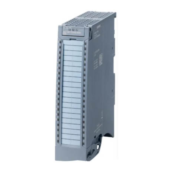
Product overview Properties Article number 6ES7531-7LH00-0AB0 View of the module Figure 2-1 View of the AI 16xU BA module Analog input module AI 16xU BA (6ES7531-7LH00-0AB0) Equipment Manual, 09/2020, A5E47052556-AA... - Page 10 • Labeling strips • U connector • Universal front door Other components You can find additional information on accessories and the article number in the system manual S7-1500/ET 200MP (https://support.industry.siemens.com/cs/ww/en/view/59191792). Analog input module AI 16xU BA (6ES7531-7LH00-0AB0) Equipment Manual, 09/2020, A5E47052556-AA...
-
Page 11: Wiring
You can find information on wiring the front connector, creating a cable shield, etc. in the Wiring section of the system manual S7-1500/ET 200MP (https://support.industry.siemens.com/cs/ww/en/view/59191792). Note Do not insert the potential jumpers supplied with the front connector. Abbreviations used... - Page 12 Wiring Block diagram and pin assignment for voltage measurement The example in the following figure shows the pin assignment for voltage measurement. ① Analog-to-digital converter (ADC) Channel or 16 x channel status (green/red) ② Backplane bus interface Status display LED (green) ③...
-
Page 13: Parameters/Address Space
Parameters/address space Measuring types and ranges Introduction The module is set to voltage measurement type with measuring range ±10 V by default. You need to reassign the module parameters with STEP 7 if you want to use a different measuring range. -
Page 14: Parameters
Parameters/address space 4.2 Parameters Parameters Parameters of AI 16xU BA When you assign the module parameters in STEP 7, you use various parameters to specify the module properties. The following table lists the configurable parameters. The effective range of the configurable parameters depends on the type of configuration. The following configurations are possible: •... -
Page 15: Declaration Of Parameters
Parameters/address space 4.3 Declaration of parameters Parameters Range of values Default Parameter as- Scope with configuration soft- setting signment in ware, e.g., STEP 7 (TIA Portal) GSD file GSD file PROFINET IO PROFIBUS DP Hardware interrupts Yes/No Channel • Hardware interrupt low limit 1 Yes/No Channel... - Page 16 Parameters/address space 4.3 Declaration of parameters Interference frequency suppression At analog input modules, this suppresses interference caused by the frequency of the AC network. The frequency of the AC voltage network may interfere with measured values, particularly for measurements within narrow voltage ranges. For this parameter, the user defines the mains frequency prevailing on his system.
-
Page 17: Address Space
Parameters/address space 4.4 Address space Low limit 1 or 2 Specifies the low limit threshold that triggers hardware interrupt 1 or 2. High limit 1 or 2 Specifies the high limit threshold that triggers hardware interrupt 1 or 2. Address space The module can be configured differently in STEP 7;... - Page 18 Parameters/address space 4.4 Address space Address space of AI 16xU BA The figure below shows the address space allocation for the configuration as 16-channel module. You can freely assign the start address for the module. The addresses of the channels are derived from the start address. "IB x"...
- Page 19 Parameters/address space 4.4 Address space The figure below shows the assignment of the address space with submodules 1 and 2. Figure 4-3 Address space for configuration as 1 x 16-channel AI 16xU BA MSI with value status Analog input module AI 16xU BA (6ES7531-7LH00-0AB0) Equipment Manual, 09/2020, A5E47052556-AA...
- Page 20 Parameters/address space 4.4 Address space The following figure shows the assignment of the address space with submodule 3 and 4. Figure 4-4 Address space for configuration as 1 x 16-channel AI 16xU BA MSI with value status Analog input module AI 16xU BA (6ES7531-7LH00-0AB0) Equipment Manual, 09/2020, A5E47052556-AA...
- Page 21 4.4 Address space Reference You can find information on the Shared Input/Output (MSI/MSO) function in the section Module-Internal Shared Input/Output (MSI/MSO) of the PROFINET with STEP 7 V16 (https://support.industry.siemens.com/cs/ww/en/view/49948856) function manual. Analog input module AI 16xU BA (6ES7531-7LH00-0AB0) Equipment Manual, 09/2020, A5E47052556-AA...
-
Page 22: Interrupts/Diagnostics Alarms
Interrupts/diagnostics alarms Status and error displays LED displays The figure below shows the LED displays (status and error displays) of AI 16xU BA. Figure 5-1 LED displays of the AI 16xU BA module Analog input module AI 16xU BA (6ES7531-7LH00-0AB0) Equipment Manual, 09/2020, A5E47052556-AA... - Page 23 Interrupts/diagnostics alarms 5.1 Status and error displays Meaning of the LED displays The following tables explain the meaning of the status and error displays. Remedial measures for diagnostic alarms can be found in section Diagnostic alarms (Page 25). RUN and ERROR LED Table 5- 1 Status and error displays RUN and ERROR LEDs...
-
Page 24: Interrupts
Interrupts/diagnostics alarms 5.2 Interrupts Interrupts Analog input module AI 16xU BA supports the following diagnostic and hardware interrupts. You can find detailed information on the event in the error organization block with the "RALRM" instruction (read additional interrupt info) and in the STEP 7 online help. Diagnostic interrupt The module generates a diagnostic interrupt at the following events: •... - Page 25 Interrupts/diagnostics alarms 5.2 Interrupts Reaction when reaching limits 1 and 2 at the same time If the two high limits 1 and 2 are reached at the same time, the module always signals the hardware interrupt for high limit 1 first. The configured value for high limit 2 is irrelevant. After processing the hardware interrupt for high limit 1, the module triggers the hardware interrupt for high limit 2.
-
Page 26: Diagnostics Alarms
RDREC or RD_REC using data record 0 and 1. The structure of the data records is available in the "Manual for interface module IM 155-5 DP ST (6ES7155-5BA00-0AB0)" on the Internet (https://support.industry.siemens.com/cs/ww/en/view/78324181). Table 5- 4 Diagnostics alarms, their meaning and corrective measures... -
Page 27: Technical Specifications
The following table shows the technical specifications as of 09/2020. You can find a data sheet including daily updated technical specifications on the Internet (https://support.industry.siemens.com/cs/ww/en/ps/td). Enter the article number or the short designation of the module on the website. Article number... - Page 28 Technical specifications Article number 6ES7531-7LH00-0AB0 Analog inputs Number of analog inputs • For voltage measurement permissible input voltage for voltage input 12 V; 12 V continuous, 30 V for max. 1 s (destruction limit), max. Input ranges (rated values), voltages •...
- Page 29 Technical specifications Article number 6ES7531-7LH00-0AB0 Smoothing of measured values • parameterizable • Step: None • Step: low • Step: Medium • Step: High Encoder Connection of signal encoders • for voltage measurement Errors/accuracies Linearity error (relative to input range), (+/-) 0.1 % Temperature error (relative to input range), (+/- 0.006 %/K...
- Page 30 Technical specifications Article number 6ES7531-7LH00-0AB0 Diagnostics indication LED Yes; green LED • RUN LED Yes; red LED • ERROR LED • MAINT LED Monitoring of the supply voltage (PWR-LED) No • Yes; green LED • Channel status display Yes; red LED •...
-
Page 31: Dimensional Drawing
Dimensional drawing The dimensional drawing of the module on the mounting rail, as well as a dimensional drawing with open front panel are provided in the appendix. Always adhere to the specified dimensions for installations in cabinets, control rooms, etc. Figure A-1 Dimensional drawing of the AI 16xU BA module Analog input module AI 16xU BA (6ES7531-7LH00-0AB0) - Page 32 Dimensional drawing Figure A-2 Dimensional drawing of the AI 16xU BA module in side view with open front cover Analog input module AI 16xU BA (6ES7531-7LH00-0AB0) Equipment Manual, 09/2020, A5E47052556-AA...
-
Page 33: Parameter Data Records
Parameter data records Parameter assignment and structure of the parameter data records The data records of the module have an identical structure, regardless of whether you configure the module with PROFIBUS DP or PROFINET IO. Dependencies for configuration with GSD file When configuring the module with a GSD file, remember that the settings of some parameters are dependent on each other. - Page 34 0 and 1. You can find additional information in the Interrupts section of the manual for the PROFIBUS DP interface module on the Internet (http://support.automation.siemens.com/WW/view/en/78324181). Assignment of data record and channel For the configuration with 1 x 16-channel, the parameters are located in data records 0 to 15 and are assigned as follows: •...
- Page 35 Parameter data records B.1 Parameter assignment and structure of the parameter data records Data record structure The figure below shows the structure of data record 0 for channel 0 as an example. The structure is identical for channels 1 to 15. The values in byte 0 and byte 1 are fixed and may not be changed.
- Page 36 Parameter data records B.1 Parameter assignment and structure of the parameter data records Figure B-2 Structure of data record 0: Bytes 7 to 19 Analog input module AI 16xU BA (6ES7531-7LH00-0AB0) Equipment Manual, 09/2020, A5E47052556-AA...
- Page 37 Parameter data records B.1 Parameter assignment and structure of the parameter data records Codes for measurement types The following table lists all measurement types of the analog input module along with their codes. Enter these codes at byte 2 of the data record for the corresponding channel (see the figure Structure of data record 0: Bytes 7 to 19).
-
Page 38: Representation Of Analog Values
Representation of analog values Introduction This appendix shows the analog values for all measuring ranges supported by the AI 16xU BA analog module. Measured value resolution Each analog value is written left aligned to the tags. The bits marked with "x" are set to "0". Table C- 1 Resolution of the analog values Resolution in bits... - Page 39 Representation of analog values C.1 Representation of input ranges Table C- 3 Unipolar input ranges Dec. val- Measured Data word Range value in % 32767 >117.589 Overflow 32511 117.589 Overshoot range 27649 100.004 27648 100.000 Nominal range 0.003617 0.000 -0.003617 Undershoot range -4864...
-
Page 40: Representation Of Analog Values In Voltage Measuring Ranges
Representation of analog values C.2 Representation of analog values in voltage measuring ranges Representation of analog values in voltage measuring ranges The following tables list the decimal and hexadecimal values (codes) of the possible voltage measuring ranges. Table C- 4 Voltage measuring ranges ±10 V, ±5 V, ±1 V, Values Voltage measuring range... -
Page 41: Measured Values For Wire Break Diagnostic
Representation of analog values C.3 Measured values for wire break diagnostic Measured values for wire break diagnostic Measured values on diagnostic event "wire break", dependent on diagnostics enables Error events initiate a diagnostics entry and trigger a diagnostics interrupt if configured accordingly.