Advertisement
Quick Links
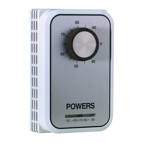
Powers
TM
ET 134 Line Voltage Room
Thermostats
134-1083
Description
Features
134-1083
134-1084, 134-1085,
134-1086
Warning/Caution Notations
Controls
134-1084 &134-1085
Exposed Knobs
The ET 134 series are line voltage, wall mounted thermostats that are available with
exposed or concealed set point adjustment. Models are available with Single-Pole,
Single-Throw (SPST) or Single-Pole, Double-Throw (SPDT) contact action and for
standard-duty (nominal 1/4 hp; 10 amps, non-inductive) or heavy-duty (nominal 1 hp;
22 amps, non-inductive) applications.
•
Locking cover with Allen screws.
Concealed auto-off-fan selector switch.
•
Adjustable high range stop.
•
•
Dual Fahrenheit and Celsius scale thermometers.
•
Separable mounting plate for mounting and wiring without removing cover.
Locking cover with Allen screws.
•
Concealed, adjustable low and high range stops.
•
Large, exposed set point knob (134-1084 and 134-1085)
•
Internal, dual Celsius and Fahrenheit scale.
•
•
Optional blank faceplate included (134-1084 and 134-1085).
WARNING
CAUTION
Technical Instructions
Document No. 155-017P25
134-1084 & 134-1085
Concealed Adjustment
Personal injury/loss of life may occur if a procedure
is not performed as specified
Equipment damage may occur if the user does not
follow a procedure as specified.
ET 134-55
August 27, 2021
134-1086
.
Siemens Industry, Inc.
Part No. 996-286 Rev. E
Advertisement

Related Manuals for Siemens Powers ET 134


Summary of Contents for Siemens Powers ET 134
- Page 1 Warning/Caution Notations WARNING Personal injury/loss of life may occur if a procedure is not performed as specified CAUTION Equipment damage may occur if the user does not follow a procedure as specified. Siemens Industry, Inc. Part No. 996-286 Rev. E...
- Page 2 125 VA, 24 Vac to 277 Vac Table 3. 134-1085 Electrical Ratings. Description cULus Volts AC 50/60 Hz Full load amperes Lock rotor amperes 55.2 Resistive amperes Pilot duty 125 VA, 24 Vac to 277 Vac Page 2 Siemens Industry, Inc.
- Page 3 Screw type terminals, terminal Screw type terminals, terminal identification molded in the block identification labelled on the barrier Ambient conditions 32°F to 105°F (0°C to 40°C) Compliance North America cULus listed; UL 60730, E60730, File E35198 Siemens Industry, Inc. Page 3...
- Page 4 Pull the required wires to this box. CAUTION: Use terminal screws furnished (No. 8-32 × 1/4-inch binder head screw). Substitution of other screws can cause problems in making proper connections. Service There is no servicing of the thermostat. Replace if inoperative. Page 4 Siemens Industry, Inc.
- Page 5 6. Turn the selector switch so that desired AUTO, OFF, or FAN reads vertically. See Figure 2. 7. Replace the thermostat cover. Tighten the screws on the bottom and top of the thermostat. The installation is now complete. Siemens Industry, Inc. Page 5...
- Page 6 Technical Instructions ET 134 Line Voltage Room Thermostats Document Number 155-017P25 August 27, 2021 Figure 2. Interior View of the 134-1083. Figure 3. Mounting a 134-1084, 134-1085 or 134-1086 Thermostat to a Conduit Box. Page 6 Siemens Industry, Inc.
- Page 7 8. Replace the cover, tighten the cover screw, and push on the knob. 9. Rotate the knob to the desired setting. Figure 4. Interior of 134-1084, 134-1085 and 134-1086 Thermostats with High and Low Adjustment Stops. Siemens Industry, Inc. Page 7...
- Page 8 Information in this publication is based on current specifications. The company reserves the right to make changes in specifications and models as design improvements are introduced. Powers is a registered trademark of Siemens Industry, Inc. Other product or company names mentioned herein may be the trademarks of their respective owners.