Table of Contents
Advertisement
Quick Links
®
Powers
Controls
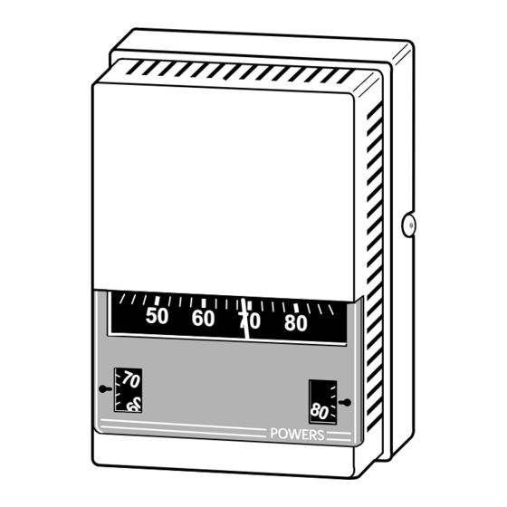
TH 192 HC Heating/Cooling Room
Thermostat
Description
Features
The TH 192 HC thermostats are proportional single output, dual setpoint, 2-pipe (high
air capacity) sensor controllers. Each thermostat includes a wall mounting plate for
installation in a variety of rough-in terminal boxes. Sensitive bimetals respond to
temperature change to modulate control air through a flapper nozzle. Two setpoint dials
are provided. When the supply air pressure changes from 18 to 25 psi (124 to 172
kPa), the thermostat automatically switches from the cooling to the heating setpoint
respectively. Air connections are made with 5/32" (4 mm) O.D. plastic tubing, directly to
the thermostat chassis for retrofit applications or with plug-in adapters (provided with
the TH 192 rough-in terminal box or optional accessories) which slide into the wall
mounting plate.
•
Direct and reverse acting models for heating and cooling modes.
•
Separate adjustable temperature setpoint indicating dials for heating and cooling.
•
Fahrenheit or Celsius setpoint dials.
•
Highly sensitive bimetal thermostatic element.
•
Individual field adjustable sensitivity with graduated scale.
•
Operating mode automatically switches between heating and cooling on change of
main air supply pressure.
•
Integral field adjustable limit stops.
•
Control pressure test port accessible without removing cover.
•
Easily replaceable thermometer, setpoint dials, filters, and restrictor plate.
•
Covers available for concealed or exposed thermometers and for either concealed,
key, or exposed knob adjustment and setpoint indication.
•
Standard plastic thermostat covers provide Desert Beige or white finish.
Technical Instructions
Document No. 155-066P25
October 26, 2010
POW ERS
TH 192-2
Siemens Industry, Inc.
Advertisement
Table of Contents

Related Manuals for Siemens TH 192 HC


Summary of Contents for Siemens TH 192 HC
- Page 1 POW ERS Description The TH 192 HC thermostats are proportional single output, dual setpoint, 2-pipe (high air capacity) sensor controllers. Each thermostat includes a wall mounting plate for installation in a variety of rough-in terminal boxes. Sensitive bimetals respond to temperature change to modulate control air through a flapper nozzle.
- Page 2 (maximum economy) and occupant comfort automatically as seasons change from the heating setpoint (65-68°F, 10-20°C) to the cooling setpoint (76-80°F, 24-27°C). TH 192 HC thermostats are available with covers that conceal or expose the setpoint adjustment dials. Figure 1. Typical TH 192 HC Thermostat Application.
- Page 3 * This feature requires a key setpoint adjustment cover (or key type cover). See Table 2. Covers See Table 2 for product number and ordering information on TH 192 HC thermostat covers. 1. Is the setpoint adjustment exposed for customer adjustment or concealed to prevent alteration of setting? 2.
-
Page 4: Specifications
Technical Instructions Document Number 155-066P25 October 26, 2010 Table 2. TH 192 HC Thermostat Cover Part Numbers. Cover Configuration Cover Part Number (See Note 2) Setpoint Setpoint Standard Standard Adjustment Thermometer Indicator Plastic Cover Metal Cover Desert Beige Desert Beige... - Page 5 Dimensions Figure 3. TH 192 HC Dimensions in Inches (Millimeters). Operation The TH 192 HC thermostat combines direct or reverse acting heating control with direct or reverse acting cooling control. In direct acting control, an increase in temperature Heating-Cooling increases the control air pressure and a decrease in temperature decreases the control Operation pressure.
-
Page 6: Thermostat Details
Document Number 155-066P25 October 26, 2010 TH 192 HC Thermostat Details Figure 5. TH 192 HC Thermostat Details. 1. Use a test thermometer to read the current room temperature. Thermometer Calibration 2. Place a screwdriver in the center of the thermometer assembly (Figure 5). Carefully rotate thermometer assembly until pointer tip indicates the correct room temperature. -
Page 7: Limit Stop Adjustment
Changing the limit stop position one gear tooth changes the limit stop setting by 1-1/3°F (0.7°C). Figure 7. TH 192 HC Limit Stop Adjustments. Sensitivity To change thermostat sensitivity, use a flat blade Adjustment... -
Page 8: Thermostat Calibration
1/8” (3.2 mm) wrench until pressure is 7 to 8 psi (48 to 55 kPa). The sensing element is now in calibration and the setpoint can be changed to the desired room temperature. Page 8 Siemens Industry, Inc. -
Page 9: Heating Calibration
TH 192 HC Heating/Cooling Room Thermostat Technical Instructions Document Number 155-066P25 October 26, 2010 Heating Calibration Step 1 — Step 2 — If not already done, remove cover using Verify that supply pressure is 25 psi (172 kPa). 192-632 calibration tool. Verify room... -
Page 10: Troubleshooting
5. Remove filters from existing connector and insert in new connector. Or, if filters are dirty, use restrictor replacement kit 192-321 to replace filters. 6. Use chassis tube connector replacement kit 192-525 to replace connector and mounting screws. Page 10 Siemens Industry, Inc. -
Page 11: Service Parts
TH 192 HC Heating/Cooling Room Thermostat Technical Instructions Document Number 155-066P25 October 26, 2010 Service Parts The following chart lists accessory parts and tools available for thermostat service. Description Part Number 141-0573 Dial thermometer (-40 to 140°F, -40 to 60°C) with pocket case... - Page 12 Information in this publication is based on current specifications. The company reserves the right to make changes in specifications and models as design improvements are introduced. Powers is a registered trademark of Siemens Industry, Inc. Other product or company names mentioned herein may be the trademarks of their respective owners.