
Related Manuals for ABB ReliaGear ASPMETER A 42


Summary of Contents for ABB ReliaGear ASPMETER A 42
- Page 1 — ReliaGear lighting panelboards — ™ Branch circuit monitoring Installation and commissioning instructions...
- Page 3 — Table of contents 004 – 013 ASPMETER solid core 014 – 026 ASPMETER split core 027 – 040 ASPMETER commissioning...
- Page 4 B R A N C H C I R C U I T M O N I T O R I N G I N S TA L L AT I O N A N D C O M M I S S I O N I N G I N S T R U C T I O N S —...
- Page 5 A S P M E T E R S O L I D C O R E — ASPMETER solid core Installer’s specifications Product identification ASPMETER Inputs Input power 50/60 Hz, 90–277 V AC Circuit breakers AQ = THQB Accuracy AE - TEY IEC 62053-21 Class 1, Power/energy...
- Page 6 B R A N C H C I R C U I T M O N I T O R I N G I N S TA L L AT I O N A N D C O M M I S S I O N I N G I N S T R U C T I O N S —...
- Page 7 A S P M E T E R S O L I D C O R E — ASPMETER solid core Blink code Data output Color and pattern Status description Monitoring at mains ASPMETERA ASPMETERB ASPMETERC Green, once per second Normal operation •...
- Page 8 B R A N C H C I R C U I T M O N I T O R I N G I N S TA L L AT I O N A N D C O M M I S S I O N I N G I N S T R U C T I O N S —...
- Page 9 A S P M E T E R S O L I D C O R E — ASPMETER solid core Configuration 3. Address the ASPMETER as any whole number between and including 1–246. Each unit is equipped with a set of eight 1.
- Page 10 B R A N C H C I R C U I T M O N I T O R I N G I N S TA L L AT I O N A N D C O M M I S S I O N I N G I N S T R U C T I O N S —...
- Page 11 A S P M E T E R S O L I D C O R E — ASPMETER solid core Mechanical installation Figure 5. Observe precautions for handling static-sensitive CTs accept a maximum #2 AWG (0.384" O.D.) wire with THHN devices to avoid damage to the circuitry, which insulation.
- Page 12 Figure 7. Recommended CT: AMP1 series available in 100 A max. to 2000 A max. Contact your local ABB sales rep for recommended CT amperages or if higher amperages are required. Figure 11. CT Input ±...
- Page 13 • Verify use of the latest release of configuration tool “NetConfig” because older versions may Modbus error on read/write not support all features in current product firmware. Latest version is available on the website http://www.veris.com/ modbus_downloads.aspx For troubleshooting or service-related questions, contact ABB at 800-782-8061 or at epis.component.support@abb.com...
- Page 14 • Each implementation of equipment using communication links must be individually and thoroughly tested for proper operation before placing it in service. For troubleshooting or service-related questions, contact ABB at 800-782-8061 or at epis.component.support@abb.com Save these instructions...
- Page 15 A S P M E T E R S P L I T C O R E — ASPMETER split core Product overview Specifications The ASPMETER panelboard monitoring system is designed Inputs to measure the current, voltage and energy consumption Input power 90–277 V AC, 50/60 Hz of up to 92 circuits (84 branch circuits, two 3-phase mains,...
- Page 16 B R A N C H C I R C U I T M O N I T O R I N G I N S TA L L AT I O N A N D C O M M I S S I O N I N G I N S T R U C T I O N S —...
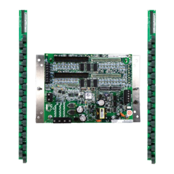
- Page 17 A S P M E T E R S P L I T C O R E — ASPMETER split core Product diagrams 1. 50-pin ribbon cable connectors: Ribbon cables attach 8. Communications settings DIP switch: Configures baud here for easy connection of adapter boards to the data rate, parity and 2-/4-wire communications.
- Page 18 B R A N C H C I R C U I T M O N I T O R I N G I N S TA L L AT I O N A N D C O M M I S S I O N I N G I N S T R U C T I O N S —...
- Page 19 A S P M E T E R S P L I T C O R E — ASPMETER split core 1. Mechanically secure the RS-485 cable where it enters Wiring the electrical panel. 2. Connect all RS-485 devices in a daisy-chain fashion, Power must be disconnected and locked out before and properly terminate the chain (Figure 3).
- Page 20 B R A N C H C I R C U I T M O N I T O R I N G I N S TA L L AT I O N A N D C O M M I S S I O N I N G I N S T R U C T I O N S —...
- Page 21 A S P M E T E R S P L I T C O R E — ASPMETER split core Address setup DO NOT USE ZERO ..
- Page 22 B R A N C H C I R C U I T M O N I T O R I N G I N S TA L L AT I O N A N D C O M M I S S I O N I N G I N S T R U C T I O N S —...
- Page 23 A S P M E T E R S P L I T C O R E — ASPMETER split core 3. Connect adapter boards to the main board using ribbon 5. Install the current sensors onto the conductors to be ±...
- Page 24 Recommended CT: AMP1 series available in 100 A max. to 2000 A max. Contact 22 23 24 25 26 27 28 29 30 31 32 33 34 35 36 37 38 39 40 41 42 your local ABB sales rep for recommended CTs amperages or if higher amperages EVEN 6 8 10 12 14 16 18 20 22 24 26 28 30 32 34 36 38 40 42 are required.
- Page 25 A S P M E T E R S P L I T C O R E — ASPMETER split core Recommended accessories 11. Connect 2-wire 90–277 V AC power to main power terminals. Observe polarity. For the ASPMETER-A Catalog number Description and ASPMETER-B, connect voltage lines to the voltage ASPCT0...
- Page 26 • Verify use of the latest release of configuration tool “NetConfig” because older versions may not support returns Modbus error on read/write all features in current product firmware. Latest version is available on the website http://www.veris.com/ modbus_downloads.aspx For troubleshooting or service-related questions, contact ABB at 800-782-8061 or at epis.component.support@abb.com...
- Page 27 • Do not install this product in hazardous or classified locations. • The installer is responsible for conformance to all applicable codes • Mount this product inside a suitable fire and electrical enclosure. For troubleshooting or service-related questions, contact ABB at 800-782-8061 or at epis.component.support@abb.com Save these instructions...
- Page 28 B R A N C H C I R C U I T M O N I T O R I N G I N S TA L L AT I O N A N D C O M M I S S I O N I N G I N S T R U C T I O N S —...
- Page 29 A S P M E T E R C O M M I S S I O N I N G — ASPMETER commissioning 6. If desired, check the option to create a desktop shortcut 8. When installation is complete, choose close to exit to open the configuration tool.
- Page 30 B R A N C H C I R C U I T M O N I T O R I N G I N S TA L L AT I O N A N D C O M M I S S I O N I N G I N S T R U C T I O N S —...
- Page 31 A S P M E T E R C O M M I S S I O N I N G — ASPMETER commissioning 2. Demand Configure device button Select the number of sub-intervals and the sub-interval After scanning for devices, the tool locates all E3x and length to be used in data collection.
- Page 32 B R A N C H C I R C U I T M O N I T O R I N G I N S TA L L AT I O N A N D C O M M I S S I O N I N G I N S T R U C T I O N S —...
- Page 33 A S P M E T E R C O M M I S S I O N I N G — ASPMETER commissioning High alarm thresholds There are two types of alarms: Latching and non-latching. Type the instantaneous current value, expressed as a Latching alarm settings defined percentage of the breaker size (default = 60%).
- Page 34 B R A N C H C I R C U I T M O N I T O R I N G I N S TA L L AT I O N A N D C O M M I S S I O N I N G I N S T R U C T I O N S —...
- Page 35 A S P M E T E R C O M M I S S I O N I N G — ASPMETER commissioning 9. Branch CT phase Global resets button Use this tab to set the phase per channel. The standard This section is used to reset data values.
- Page 36 B R A N C H C I R C U I T M O N I T O R I N G I N S TA L L AT I O N A N D C O M M I S S I O N I N G I N S T R U C T I O N S —...
- Page 37 A S P M E T E R C O M M I S S I O N I N G — ASPMETER commissioning Branch current alarms Configuring alarm registers Latching alarms are cleared by writing a 0 to its alarm bit. Latching alarms A write to a non-latching alarm is ignored.
- Page 38 B R A N C H C I R C U I T M O N I T O R I N G I N S TA L L AT I O N A N D C O M M I S S I O N I N G I N S T R U C T I O N S —...
- Page 39 A S P M E T E R C O M M I S S I O N I N G — ASPMETER commissioning Latching alarm examples Amps Amps Time Time Latching High Latching L delay alarm ON time alarm ON time alarm delay alarm ON time LL delay...
- Page 40 0035 0x1d 0075 0x3d 0135 0x5d 0175 0x7d (rs) 0036 0x1e > 0076 0x3e 0136 0x5e 0176 0x7e (us) 0037 0x1f 0077 0x3f 0137 0x5f (del) 0177 0x7f For troubleshooting or service-related questions, contact ABB at 800-782-8061 or at epis.component.support@abb.com...
- Page 41 A S P M E T E R C O M M I S S I O N I N G , N OT E S — Notes...
- Page 42 B R A N C H C I R C U I T M O N I T O R I N G I N S TA L L AT I O N A N D C O M M I S S I O N I N G I N S T R U C T I O N S —...
- Page 43 B R A N C H C I R C U I T M O N I T O R I N G I N S TA L L AT I O N A N D C O M M I S S I O N I N G I N S T R U C T I O N S...
- Page 44 Any reproduction, disclosure to third parties or utilization of its contents – in whole or in parts – is forbidden without prior written consent of ABB Inc. © 2022 ABB All rights reserved ReliaGear is a trademark of ABB Inc.