
Related Manuals for Dell E01B002


Summary of Contents for Dell E01B002
- Page 1 Dell PowerEdge FC430 Owner's Manual Regulatory Model: E01B Series Regulatory Type: E01B002 April 2020 Rev. A13...
- Page 2 A WARNING indicates a potential for property damage, personal injury, or death. © 2016 Dell Inc. All rights reserved. This product is protected by U.S. and international copyright and intellectual property laws. Dell and the Dell logo are trademarks of Dell Inc. in the United States and/or other jurisdictions. All other marks and names mentioned herein may be...
-
Page 3: Table Of Contents
Contents Chapter 1: PowerEdge FC430 system overview................6 Supported configurations for FC430 system....................... 6 Front panel.................................... 6 Front panel view—single SSD system........................6 Front panel view—dual SSD system.........................7 Diagnostic indicators on the front panel........................8 Health status indicator..............................8 SSD activity indicator codes............................9 iDRAC Direct LED indicator codes..........................9 Locating Service Tag of your system..........................10 Chapter 2: Documentation resources....................11... - Page 4 Settings utility..............................44 Device Settings................................45 Dell Lifecycle Controller..............................45 Embedded systems management..........................45 Boot Manager..................................46 Viewing Boot Manager............................... 46 Boot Manager main menu............................46 PXE boot....................................47 Chapter 6: Installing and removing sled components..............48 Safety instructions................................48 Before working inside your system......................... 48 After working inside your system..........................
- Page 5 Initializing the TPM for BitLocker users....................... 104 Initializing the TPM for TXT users......................... 104 Chapter 7: Using system diagnostics..................105 Dell Embedded System Diagnostics..........................105 When to use the Embedded System Diagnostics....................105 Running the Embedded System Diagnostics...................... 105 System diagnostics controls........................... 106 Chapter 8: Jumpers and connectors ..................
-
Page 6: Chapter 1: Poweredge Fc430 System Overview
PowerEdge FC430 system overview The Dell PowerEdge FC430 system is a quarter-width sled that supports up to: ● Two Intel Xeon E5-2600 v4 processors ● Eight DIMMs ● Two 1.8-inch uSATA solid state drives (SSDs). Topics: • Supported configurations for FC430 system •... -
Page 7: Front Panel View-Dual Ssd System
Enables you to connect USB devices to the sled or provides iDRAC Direct port access to the iDRAC Direct features. For more information about iDRAC, see the iDRAC Guide at Dell.com/idracmanuals. This port is USB 2.0 compliant. A single 1.8-inch hot-swappable uSATA SSD is supported in this chassis. -
Page 8: Diagnostic Indicators On The Front Panel
Enables you to connect USB devices to the sled or provides iDRAC Direct port access to the iDRAC Direct features. For more information about iDRAC, see the iDRAC Guide at Dell.com/idracmanuals. This port is USB 2.0 compliant. SSD (2) Up to two 1.8-inch hot-swappable uSATA SSDs are supported in this chassis. -
Page 9: Ssd Activity Indicator Codes
SSD activity indicator codes The Solid State Drive (SSD) indicators display different patterns as drive events occur in the system. NOTE: The sled must have an SSD or an SSD blank installed in each drive bay. Figure 4. SSD indicators 1. -
Page 10: Locating Service Tag Of Your System
Alternatively, the information may be on a sticker on the chassis of the system. This information is used by Dell to route support calls to the appropriate personnel. -
Page 11: Chapter 2: Documentation Resources
Methods to download firmware and drivers section in this document. Managing your system For information about systems management Dell.com/openmanagemanuals software offered by Dell, see the Dell OpenManage Systems Management Overview Guide. For information about setting up, using, and Dell.com/openmanagemanuals troubleshooting OpenManage, see the Dell OpenManage Server Administrator User’s... - Page 12 Understanding event and For information about checking the event and Dell.com/openmanagemanuals > OpenManage error messages error messages generated by the system software firmware and agents that monitor system components, see the Dell Event and Error Messages Reference Guide. Documentation resources...
-
Page 13: Chapter 3: Technical Specifications
Technical specifications The technical and environmental specifications of your system are outlined in this section. Topics: • Chassis dimensions and weight • Processor specifications • System battery specification • Memory specifications • RAID controller • Drive specifications • Ports and connectors specifications •... -
Page 14: Processor Specifications
Processor specifications The PowerEdge FC430 system supports up to two Intel Xeon E5-2600 v4 processors. System battery specification The PowerEdge FC430 system supports CR 2032 3.0-V lithium coin cell system battery. Memory specifications The PowerEdge FC430 system supports DDR4 registered DIMMs (RDIMMs and LRDIMMs). Table 10. -
Page 15: Video Specification
The PowerEdge FC430 supports Matrox G200eR2 video controller. The available memory is 16 MB which is shared with the iDRAC application memory. Environmental specifications NOTE: For additional information about environmental measurements for specific system configurations, see Dell.com/ environmental_datasheets. Table 11. Temperature specifications Temperature... -
Page 16: Particulate And Gaseous Contamination Specifications
Particulate and gaseous contamination specifications The following table defines the limitations that will help avoid any damages to the IT equipment and/or failure from particulates and gaseous contamination. If the levels of particulates or gaseous pollution exceed the specified limitations and result in equipment damage or failure, you may need to rectify the environmental conditions. -
Page 17: Expanded Operating Temperature Restrictions
Expanded operating temperature restrictions Table 20. Expanded operating temperature restrictions System Processor DIMM Operating temperature configuration (in watts) 120 W Up to 25ºC ambient RDIMM: 4 GB, 8 GB, 16 GB, and 32 GB 120 W LRDIMM: 64 GB Up to 20ºC ambient 105 W Up to 30ºC ambient RDIMM: 4 GB, 8 GB, 16 GB, and 32 GB... -
Page 18: Chapter 4: Initial System Setup And Configuration
19 iDRAC configuration The Integrated Dell Remote Access Controller (iDRAC) is designed to make system administrators more productive and improve the overall availability of Dell systems. iDRAC alerts administrators to system issues, helps them perform remote system management, and reduces the need for physical access to the system. -
Page 19: Options To Install The Operating System
The default user name and password are root and calvin. You can also log in by using Single Sign-On or Smart Card. NOTE: You must have iDRAC credentials to log in to iDRAC. For more information about logging in to iDRAC and iDRAC licenses, see the Integrated Dell Remote Access Controller User's Guide at Dell.com/idracmanuals. Options to install the operating system... - Page 20 Using Dell OpenManage Deployment Toolkit (DTK) Dell.com/openmanagemanuals Downloading the drivers and firmware Dell recommends that you download and install the latest BIOS, drivers, and systems management firmware on your system. Prerequisites Ensure that you clear the web browser cache before downloading the drivers and firmware.
-
Page 21: Chapter 5: Pre-Operating System Management Applications
Options to manage the pre-operating system applications Your system has the following options to manage the pre-operating system applications: ● System Setup ● Boot Manager ● Dell Lifecycle Controller ● Preboot Execution Environment (PXE) Related concepts System Setup on page 21... -
Page 22: Viewing System Setup
The iDRAC settings utility is an interface to set up and configure the iDRAC parameters by using UEFI (Unified Extensible Firmware Interface). You can enable or disable various iDRAC parameters by using the iDRAC settings utility. For more information about this utility, see Integrated Dell Remote Access Controller User’s Guide at Dell.com/idracmanuals. - Page 23 Boot Settings on page 24 Network Settings on page 26 System Security on page 28 System Information on page 32 Memory Settings on page 34 Processor Settings on page 35 SATA Settings on page 37 Integrated Devices on page 38 Serial Communication on page 40 System Profile Settings...
- Page 24 Option Description Integrated Specifies options to manage integrated device controllers and ports and specify related features and Devices options. Serial Specifies options to manage the serial ports and specify related features and options. Communication System Profile Specifies options to change the processor power management settings, memory frequency, and so on. Settings System Security Specifies options to configure the system security settings, such as system password, setup password,...
- Page 25 Related tasks Boot Settings details on page 25 Changing the boot order on page 26 Boot Settings details About this task The Boot Settings screen details are explained as follows: Option Description Boot Mode Enables you to set the boot mode of the system. CAUTION: Switching the boot mode may prevent the system from booting if the operating system is not installed in the same boot mode.
- Page 26 Operating systems must be UEFI-compatible to be installed from the UEFI boot mode. DOS and 32-bit operating systems do not support UEFI and can only be installed from the BIOS boot mode. NOTE: For the latest information about supported operating systems, go to Dell.com/ossupport. Related references Boot Settings...
- Page 27 Viewing Network Settings To view the Network Settings screen, perform the following steps: Steps 1. Turn on, or restart your system. 2. Press F2 immediately after you see the following message: F2 = System Setup NOTE: If your operating system begins to load before you press F2, wait for the system to finish booting, and then restart your system and try again.
- Page 28 Viewing UEFI iSCSI Settings To view the UEFI iSCSI Settings screen, perform the following steps: Steps 1. Turn on, or restart your system. 2. Press F2 immediately after you see the following message: F2 = System Setup NOTE: If your operating system begins to load before you press F2, wait for the system to finish booting, and then restart your system and try again.
- Page 29 Deleting or changing system and setup password on page 31 Viewing System Security To view the System Security screen, perform the following steps: Steps 1. Turn on, or restart your system. 2. Press F2 immediately after you see the following message: F2 = System Setup NOTE: If your operating system begins to load before you press F2, wait for the system to finish booting, and then...
- Page 30 Option Description AC Power Sets how the system behaves after AC power is restored to the system. This option is set to Last by Recovery default. UEFI Variable Provides varying degrees of securing UEFI variables. When set to Standard (the default), UEFI variables Access are accessible in the operating system per the UEFI specification.
- Page 31 Using your system password to secure your system If you have assigned a setup password, the system accepts your setup password as an alternate system password. Steps 1. Turn on or reboot your system. 2. Type the system password and press Enter. Next steps When Password Status is set to Locked, type the system password and press Enter when prompted at reboot.
- Page 32 Related references System Security on page 28 Secure Boot Custom Policy Settings Secure Boot Custom Policy Settings is displayed only when Secure Boot Policy is set to Custom. Viewing Secure Boot Custom Policy Settings To view the Secure Boot Custom Policy Settings screen, perform the following steps: Steps 1.
- Page 33 Viewing System Information To view the System Information screen, perform the following steps: Steps 1. Turn on, or restart your system. 2. Press F2 immediately after you see the following message: F2 = System Setup NOTE: If your operating system begins to load before you press F2, wait for the system to finish booting, and then restart your system and try again.
- Page 34 Specifies the memory operating mode. The options available are Optimizer Mode, Advanced ECC Operating Mode Mode, Mirror Mode, Spare Mode, Spare with Advanced ECC Mode, Dell Fault Resilient Mode and Dell NUMA Fault Resilient Mode. This option is set to Optimizer Mode by default.
- Page 35 NOTE: The Dell Fault Resilient Mode option establishes an area of memory that is fault resilient. This mode can be used by an operating system that supports the feature to load critical applications or enables the operating system kernel to maximize system availability.
- Page 36 This option is only available on certain stock keeping units (SKUs) of the processors. X2Apic Mode Enables or disables the X2Apic mode. Dell Controlled Controls the turbo engagement. Enable this option only when System Profile is set to Performance. Turbo NOTE: Depending on the number of installed CPUs, there may be up to four processor listings.
- Page 37 Option Description Option Description Family-Model- Specifies the family, model, and stepping of the processor as defined by Intel. Stepping Brand Specifies the brand name. Level 2 Cache Specifies the total L2 cache. Level 3 Cache Specifies the total L3 cache. Number of Cores Specifies the number of cores per processor.
- Page 38 SATA Settings details About this task The SATA Settings screen details are explained as follows: Option Description Embedded SATA Enables the embedded SATA option to be set to Off, ATA, AHCI, or RAID modes. This option is set to AHCI by default. Security Freeze Sends Security Freeze Lock command to the Embedded SATA drives during POST.
- Page 39 Viewing Integrated Devices To view the Integrated Devices screen, perform the following steps: Steps 1. Turn on, or restart your system. 2. Press F2 immediately after you see the following message: F2 = System Setup NOTE: If your operating system begins to load before you press F2, wait for the system to finish booting, and then restart your system and try again.
- Page 40 Option Description OS Watchdog If your system stops responding, this watchdog timer aids in the recovery of your operating system. When Timer this option is set to Enabled, the operating system initializes the timer. When this option is set to Disabled (the default), the timer does not have any effect on the system.
- Page 41 Serial Communication details About this task The Serial Communication screen details are explained as follows: Option Description Serial Enables the COM port or Console Redirection options. This option is set to Off by default. Communication Serial Port Enables you to set the port address for serial devices. This option is set to Serial Device 1=COM2, Address Serial Device 2=COM1 by default.
- Page 42 You can only change the rest of the options if the mode is set to Custom. This option is set to Performance Per Watt Optimized (DAPC) by default. DAPC is Dell Active Power Controller.
- Page 43 Option Description Number of Turbo NOTE: If there are two processors installed in the system, you see an entry for Number of Turbo Boot Enabled Boost Enabled Cores for Processor 2. Cores for Controls the number of turbo boost enabled cores for processor 1. The maximum number of cores is Processor 1 enabled by default.
-
Page 44: Idrac Settings Utility
NOTE: Accessing some of the features on the iDRAC settings utility needs the iDRAC Enterprise License upgrade. For more information about using iDRAC, see Dell Integrated Dell Remote Access Controller User's Guide at Dell.com/ idracmanuals. Related concepts... -
Page 45: Device Settings
Dell Lifecycle Controller Dell Lifecycle Controller (LC) provides advanced embedded systems management capabilities including system deployment, configuration, update, maintenance, and diagnosis. LC is delivered as part of the iDRAC out-of-band solution and Dell system embedded Unified Extensible Firmware Interface (UEFI) applications. -
Page 46: Boot Manager
NOTE: Certain platform configurations may not support the full set of features provided by the Dell Lifecycle Controller. For more information about setting up the Dell Lifecycle Controller, configuring hardware and firmware, and deploying the operating system, see the Dell Lifecycle Controller documentation at Dell.com/idracmanuals. -
Page 47: Pxe Boot
Related references Boot Manager on page 46 Related tasks Viewing Boot Manager on page 46 One-shot BIOS boot menu One-shot BIOS boot menu enables you to select a boot device to boot from. Related references Boot Manager on page 46 System Utilities System Utilities contains the following utilities that can be launched: ●... -
Page 48: Chapter 6: Installing And Removing Sled Components
Damage due to servicing that is not authorized by Dell is not covered by your warranty. Read and follow the safety instructions that are shipped with your product. -
Page 49: After Working Inside Your System
If you are permanently removing the sled, install a sled blank. Operating the system for extended periods of time without a sled blank installed can cause the enclosure to overheat. NOTE: For more information about the interposer connections, see Dell PowerEdge FX2 and FX2s Enclosure Owner’s Manual at Dell.com/poweredgemanuals. Installing and removing sled components... -
Page 50: Installing A Sled
Figure 6. Removing a sled 1. release button 2. sled handle 3. sled 4. FX2 or FX2s enclosure Next steps 1. Follow the procedure listed in the After working inside your system section. Related references Safety instructions on page 48 Related tasks Before working inside your system on page 48... -
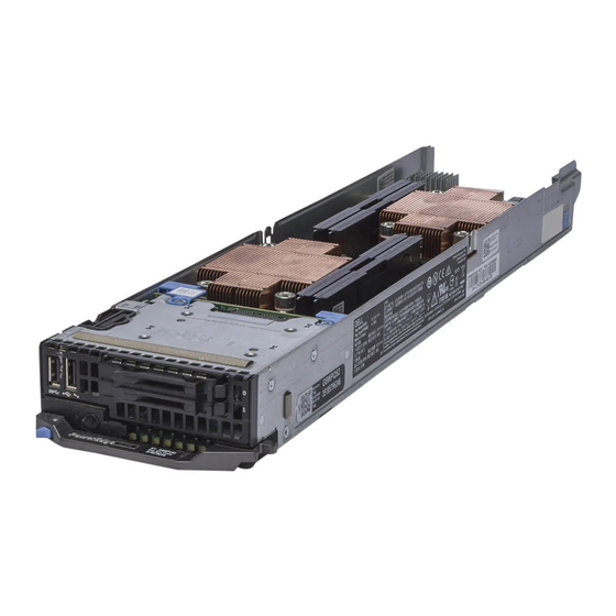
Page 51: Inside The Sled
Figure 7. Installing a sled 1. release button 2. sled handle 3. sled 4. FX2 or FX2s enclosure Related references Safety instructions on page 48 Inside the sled Figure 8. Inside the sled 1. SSD cage 2. vFlash/SD card multifunction slot 3. -
Page 52: Cooling Shroud
Damage due to servicing that is not authorized by Dell is not covered by your warranty. Read and follow the safety instructions that are shipped with your product. -
Page 53: Installing The Cooling Shroud
Damage due to servicing that is not authorized by Dell is not covered by your warranty. Read and follow the safety instructions that came with the product. - Page 54 Figure 10. Installing the cooling shroud 1. cooling shroud latch 2. finger hold points 3. cooling shroud 4. cooling shroud guide 5. cooling shroud guide slot on chassis Next steps Follow the procedure listed in the After working inside your system section. Related references Safety instructions on page 48...
-
Page 55: System Memory
System memory Your system supports DDR4 registered DIMMs (RDIMMs and LRDIMMs), and DDR4 voltage specifications. NOTE: MT/s indicates DIMM speed in MegaTransfers per second. Memory bus operating frequency can be 2400 MT/s, 2133 MT/s, or 1866 MT/s depending on: ● System profile selected (for example, Performance Optimized, Custom, or Dense Configuration Optimized) ●... -
Page 56: General Memory Module Installation Guidelines
The following table shows the memory populations and operating frequencies for the supported configurations. Table 23. Memory population—operating frequency for supported configuration DIMM DIMMs populated Volatge Operating Frequency (in Maximum DIMM Rank Per Channel Type per channel MT/s) RDIMM 1.2 v 2400, 2133, 1866 Single rank 2400, 2133, 1866... -
Page 57: Mode-Specific Guidelines
● Populate all the sockets with white release tabs first, followed by the black release tabs, and then the green release tabs. ● When mixing memory modules with different capacities, populate the sockets with memory modules with highest capacity first. For example, if you want to mix 4 GB and 8 GB memory modules, populate 8 GB memory modules in the sockets with white release tabs and 4 GB memory modules in the sockets with black release tabs. -
Page 58: Sample Memory Configurations
NOTE: Advanced ECC with mirroring is not supported. Memory optimized (independent channel) mode This mode supports Single Device Data Correction (SDDC) only for memory modules that use x4 device width. It does not impose any specific slot population requirements. Table 26. Memory optimized (independent channel) mode Processor Configuration Memory population rules... - Page 59 Table 28. Memory configurations—single processor (continued) System Capacity DIMM Size (in Number of Organization and DIMM Slot Population (in GB) DIMMs Speed A1, A2, A3, A4 1R x8, 2400 MT/s A1, A2 1R x8 2400 MT/s 2R x8, 2400 MT/s A1, A2, A3, A4 1R x8 2400 MT/s A1, A2...
-
Page 60: Removing Memory Modules
Damage due to servicing that is not authorized by Dell is not covered by your warranty. Read and follow the safety instructions that are shipped with your product. -
Page 61: Installing Memory Modules
Damage due to servicing that is not authorized by Dell is not covered by your warranty. Read and follow the safety instructions that are shipped with your product. -
Page 62: Pcie Mezzanine Card
Figure 13. Installing the memory module a. memory module b. alignment key c. memory module socket ejector (2) Next steps 1. Install the cooling shroud. 2. Follow the procedure listed in the After working inside your system section. 3. Press F2 to enter System Setup, and check the System Memory setting. The system should have already changed the value to reflect the installed memory. -
Page 63: Removing The Pcie Mezzanine Card
Damage due to servicing that is not authorized by Dell is not covered by your warranty. Read and follow the safety instructions that are shipped with your product. - Page 64 Figure 15. Removing a PCIe mezzanine card 1. screw hole on SSD cage (2) 2. external storage connector (2) 3. PCIe mezzanine bridge card 4. Screw (2) 5. PCIe mezzanine card 6. SSD cage Next steps 1. Install the PCIe mezzanine card. 2.
-
Page 65: Installing The Pcie Mezzanine Card
Damage due to servicing that is not authorized by Dell is not covered by your warranty. Read and follow the safety instructions that are shipped with your product. -
Page 66: Internal Dual Sd Module (Idsdm) Card
Figure 16. Installing the PCIe mezzanine card 1. screw hole on SSD cage (2) 2. external storage connector (2) 3. PCIe mezzanine bridge card 4. Screw (2) 5. PCIe mezzanine card 6. SSD cage Next steps 1. Install the SSD cage. 2. -
Page 67: Removing An Internal Sd Card
Damage due to servicing that is not authorized by Dell is not covered by your warranty. Read and follow the safety instructions that are shipped with your product. -
Page 68: Installing An Internal Sd Card
Damage due to servicing that is not authorized by Dell is not covered by your warranty. Read and follow the safety instructions that are shipped with your product. -
Page 69: Removing The Idsdm Card
Damage due to servicing that is not authorized by Dell is not covered by your warranty. Read and follow the safety instructions that came with the product. -
Page 70: Installing The Idsdm Card
Figure 19. Removing the IDSDM card 1. screw (2) 2. screw hole (2) 3. standoff (1) 4. SSD cage 5. IDSDM card Next steps 1. Install the SSD cage. 2. Install the IDSDM card. 3. If applicable, install the SD cards. 4. - Page 71 Damage due to servicing that is not authorized by Dell is not covered by your warranty. Read and follow the safety instructions that came with the product. NOTE: You must remove the IDSDM card to replace a faulty IDSDM card.
-
Page 72: Sd Vflash Card
Damage due to servicing that is not authorized by Dell is not covered by your warranty. Read and follow the safety instructions that came with the product. -
Page 73: Installing The Sd Vflash Card
Damage due to servicing that is not authorized by Dell is not covered by your warranty. Read and follow the safety instructions that are shipped with your product. -
Page 74: Lan On Motherboard (Lom) Riser Card
Damage due to servicing that is not authorized by Dell is not covered by your warranty. Read and follow the safety instructions that came with the product. -
Page 75: Installing The Lom Riser Card
1. Follow the safety guidelines listed in the Safety instructions section. 2. Follow the procedure listed in the Before working inside your system section. 3. Keep the Phillips #2 screwdriver ready. Steps 1. Remove the two screws that secure the LOM riser card to the system board. 2. - Page 76 Damage due to servicing that is not authorized by Dell is not covered by your warranty. Read and follow the safety instructions that came with the product. NOTE: You must remove the LOM riser card to replace a faulty LOM riser card or service other components inside the system.
-
Page 77: Processors
Damage due to servicing that is not authorized by Dell is not covered by your warranty. Read and follow the safety instructions that are shipped with your product. - Page 78 Figure 25. Removing the 120 W heat sink 1. captive screw (4) 2. heat sink 3. processor socket 4. screw hole (4) 2. To remove a 140 W heat sink, perform the following steps. a. Loosen one of the screws that secure the heat sink over CPU 1 to the system board. Wait 30 seconds for the heat sink to loosen from the processor.
-
Page 79: Removing A Processor
Damage due to servicing that is not authorized by Dell is not covered by your warranty. Read and follow the safety instructions that are shipped with your product. - Page 80 Figure 27. Processor shield opening and closing lever sequence a. socket-release lever 1 b. processor c. socket-release lever 2 3. Hold the tab on the processor shield and rotate the shield upward and out of the way. 4. Lift the processor out of the socket and leave the release lever up so that the socket is ready for the new processor. CAUTION: If you are permanently removing a processor, you must install a socket protective cap and a processor blank in the vacant socket to ensure proper system cooling.
- Page 81 Figure 28. Removing a processor 1. socket-release lever 1 2. pin–1 corner of the processor 3. processor 4. slot (4) 5. processor shield 6. socket-release lever 2 7. processor socket 8. tab (4) Next steps 1. If you are removing the processor permanently, install the processor blank. 2.
-
Page 82: Installing A Processor
Damage due to servicing that is not authorized by Dell is not covered by your warranty. Read and follow the safety instructions that are shipped with your product. -
Page 83: Installing A Heat Sink
Damage due to servicing that is not authorized by Dell is not covered by your warranty. Read and follow the safety instructions that are shipped with your product. -
Page 84: Processor Blank And Dimm Blank
Figure 29. Applying thermal grease on the top of the processor a. processor b. thermal grease c. thermal grease syringe 3. Place the heat sink onto the processor. 4. Tighten one of the four screws to secure the heat sink to the system board. 5. -
Page 85: Removing A Processor Blank And Dimm Blank
Damage due to servicing that is not authorized by Dell is not covered by your warranty. Read and follow the safety instructions that came with the product. -
Page 86: Installing A Processor Blank And Dimm Blank
Damage due to servicing that is not authorized by Dell is not covered by your warranty. Read and follow the safety instructions that came with the product. -
Page 87: Removing An Ssd From An Ssd Carrier
Damage due to servicing that is not authorized by Dell is not covered by your warranty. Read and follow the safety instructions that came with the product. -
Page 88: Installing An Ssd Into An Ssd Carrier
Damage due to servicing that is not authorized by Dell is not covered by your warranty. Read and follow the safety instructions that came with the product. -
Page 89: Removing An Ssd Carrier
Damage due to servicing that is not authorized by Dell is not covered by your warranty. Read and follow the safety instructions that came with the product. -
Page 90: Installing An Ssd Carrier
Installing an SSD carrier Prerequisites CAUTION: When a replacement hot swappable SSD is installed and the sled is powered on, the SSD automatically begins to rebuild. Make absolutely sure that the replacement SSD is blank or contains data that you wish to have over-written. Any data on the replacement SSD is immediately lost after the SSD is installed. NOTE: You must remove an SSD to upgrade an SSD or replace a faulty SSD. -
Page 91: Removing An Ssd Blank
Damage due to servicing that is not authorized by Dell is not covered by your warranty. Read and follow the safety instructions that came with the product. -
Page 92: Installing An Ssd Blank
Damage due to servicing that is not authorized by Dell is not covered by your warranty. Read and follow the safety instructions that came with the product. -
Page 93: Installing The Ssd Cage
Damage due to servicing that is not authorized by Dell is not covered by your warranty. Read and follow the safety instructions that came with the product. - Page 94 1. Follow the safety guidelines listed in the Safety instructions section. 2. Follow the procedure listed in the Before working inside your system section. 3. Keep the Phillips #1 screwdriver ready. Steps 1. Align the slots on the sides of the SSD cage with the guide pins on the chassis. 2.
-
Page 95: Configuring The Boot Drive
Damage due to servicing that is not authorized by Dell is not covered by your warranty. Read and follow the safety instructions that came with the product. -
Page 96: Installing The Ssd Backplane
Damage due to servicing that is not authorized by Dell is not covered by your warranty. Read and follow the safety instructions that came with the product. -
Page 97: System Battery
Figure 40. Installing the SSD backplane 1. SSD backplane connector on system board 2. captive screw (2) 3. SSD backplane 4. screw hole on the SSD cage (2) 5. SSD cage Next steps 1. Install the SSD carriers into their original bays. 2. - Page 98 Damage due to servicing that is not authorized by Dell is not covered by your warranty. Read and follow the safety instructions that are shipped with your product.
-
Page 99: System Board
Damage due to servicing that is not authorized by Dell is not covered by your warranty. Read and follow the safety instructions that came with the product. - Page 100 ● PCIe mezzanine card ● LOM riser card 4. Keep the Phillips #2 screwdriver, along with the 4 mm and 5 mm Hex nut drivers ready. CAUTION: Do not lift the system board by holding a memory module, processor, or other components. CAUTION: You must temporarily label the SSD before removal so that you can replace them in their original bays.
-
Page 101: Installing The System Board
Damage due to servicing that is not authorized by Dell is not covered by your warranty. Read and follow the safety instructions that came with the product. -
Page 102: Restoring The Service Tag By Using The Easy Restore Feature
NOTE: If you are not installing the sled in the enclosure, install the I/O connector cover. 4. Import your new or existing iDRAC Enterprise license. See the iDRAC8 User's Guide at Dell.com/idracmanuals. 5. Ensure that you: a. Use the Easy Restore feature to restore the Service Tag. For more information, see the Restoring the Service Tag using Easy Restore section. -
Page 103: Entering The System Service Tag By Using System Setup
Damage due to servicing that is not authorized by Dell is not covered by your warranty. Read and follow the safety instructions that are shipped with your product. -
Page 104: Initializing The Tpm For Bitlocker Users
4. Press the plastic rivet until the rivet snaps into place. Figure 46. Installing the TPM 1. rivet slot on the system board 2. plastic rivet 3. TPM 4. TPM connector Next steps 1. Install the system board. 2. Follow the procedure listed in the After working inside your system section. Initializing the TPM for BitLocker users Steps Initialize the TPM. -
Page 105: Chapter 7: Using System Diagnostics
Using system diagnostics If you experience a problem with your system, run the system diagnostics before contacting Dell for technical assistance. The purpose of running system diagnostics is to test your system hardware without requiring additional equipment or risking data loss. -
Page 106: System Diagnostics Controls
Displays a time-stamped log of the results of all tests run on the system. This is displayed if at least one event description is recorded. For information about embedded system diagnostics, see the Dell Enhanced Pre-boot System Assessment User Guide at Dell.com/support/home. -
Page 107: Chapter 8: Jumpers And Connectors
Damage due to servicing that is not authorized by Dell is not covered by your warranty. Read and follow the safety instructions that are shipped with your product. -
Page 108: System Board Connectors
Damage due to servicing that is not authorized by Dell is not covered by your warranty. Read and follow the safety instructions that came with the product. - Page 109 Steps 1. Turn off the sled using the operating system commands or the CMC. 2. Remove the sled from the enclosure. 3. Relocate the jumper plug to disable the password feature. 4. Install the sled in the enclosure. 5. Turn on the sled. When the sled is on, the power-on indicator is solid green.
-
Page 110: Chapter 9: Troubleshooting Your System
Damage due to servicing that is not authorized by Dell is not covered by your warranty. Read and follow the safety instructions that are shipped with your product. -
Page 111: Troubleshooting Solid State Drives
Damage due to servicing that is not authorized by Dell is not covered by your warranty. Read and follow the safety instructions that are shipped with your product. -
Page 112: Troubleshooting An Internal Sd Card
Damage due to servicing that is not authorized by Dell is not covered by your warranty. Read and follow the safety instructions that are shipped with your product. -
Page 113: Troubleshooting The System Board
Damage due to servicing that is not authorized by Dell is not covered by your warranty. Read and follow the safety instructions that are shipped with your product. - Page 114 If the date and time are not correct in the System Setup, replace the battery. If the problem is not resolved by replacing the battery, see the Getting help section. NOTE: If the sled is turned off for long periods of time (for weeks or months), the NVRAM may lose its system configuration information.
-
Page 115: Chapter 10: Getting Help
Dell product catalog. Availability varies by country and product, and some services may not be available in your area. To contact Dell for sales, technical assistance, or...