Dell PowerEdge FC430 Owner's Manual
Hide thumbs
Also See for PowerEdge FC430:
- Getting started with your system (2 pages) ,
- Owner's manual (115 pages)

Related Manuals for Dell PowerEdge FC430


Summary of Contents for Dell PowerEdge FC430
- Page 1 Dell PowerEdge FC430 Owner's Manual Regulatory Model: E01B Series Regulatory Type: E01B002...
- Page 2 WARNING: A WARNING indicates a potential for property damage, personal injury, or death. Copyright © 2015 Dell Inc. All rights reserved. This product is protected by U.S. and international copyright and intellectual property laws. Dell and the Dell logo are trademarks of Dell Inc.
-
Page 3: Table Of Contents
Contents 1 About your Dell PowerEdge FC430..............7 ...................... 7 Front panel features and indicators ........................9 SSD activity indicator codes ..................... 10 iDRAC Direct LED indicator codes ........................12 Documentation matrix ........................13 Quick Resource Locator 2 Performing initial system configuration............14 ........................14... - Page 4 ...................... 30 Choosing the system boot mode ....................30 Assigning a system or setup password .................31 Using your system password to secure your system ........... 31 Deleting or changing an existing system password or setup password ..................32 Operating with a setup password enabled ......................
- Page 5 ............................59 Processors ........................59 Removing a heat sink ........................61 Removing a processor ........................64 Installing a processor ........................65 Installing a heat sink ....................... 67 Processor-and-DIMM blank ..................67 Removing a processor-and-DIMM blank ..................68 Installing a processor-and-DIMM blank ........................69 Solid State Drives (SSD) ......................
- Page 6 ....................90 Troubleshooting the system board ..................90 Troubleshooting the NVRAM backup battery 6 Using system diagnostics..................92 ....................92 Dell Embedded System Diagnostics ................ 92 When to use the Embedded System Diagnostics ................92 Running the Embedded System Diagnostics ......................93 System diagnostics controls 7 Jumpers and connectors..................
-
Page 7: About Your Dell Poweredge Fc430
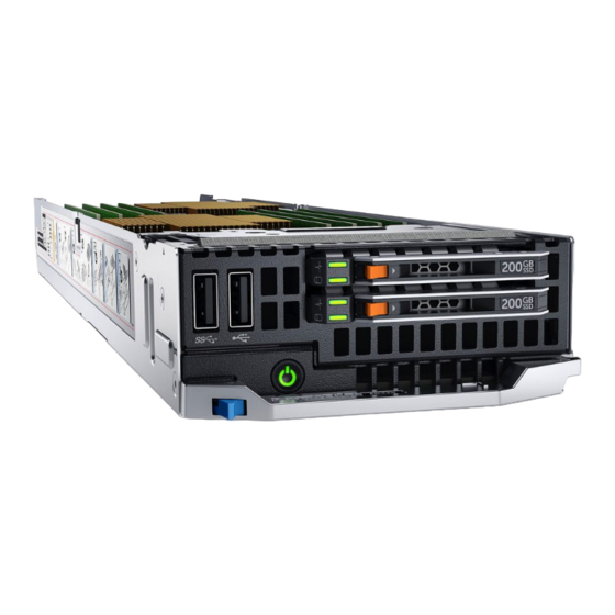
About your Dell PowerEdge FC430 The Dell PowerEdge FC430 is a quarter width sled that supports up to two processors based on the Intel Haswell EP product family, up to eight DIMMs, and up to two 1.8” uSATA Solid State Drives (SSD). - Page 8 Item Indicator, Icon Description Button, or Connector port / iDRAC iDRAC Guide at dell.com/ Direct port esmmanuals for more information.This port is USB 2.0 compliant. SSD (2) Up to two 1.8 inch, hot-swappable uSATA SSDs are supported in this chassis.
-
Page 9: Ssd Activity Indicator Codes
Direct features. Refer to the Direct port iDRAC Guide at dell.com/ esmmanuals for more information. This port is USB 2.0 compliant. A single 1.8 inch, hot-swappable uSATA SSD is supported in this chassis. -
Page 10: Idrac Direct Led Indicator Codes
Figure 3. SSD indicators drive activity indicator (green) drive status indicator (green and amber) NOTE: If the drive is in theAdvanced Host Controller Interface (AHCI) mode, the status LED (on the right side) does not function and remains OFF. Drive-Status Indicator Pattern Condition Identifying the drive or preparing for removal Blinks green two times per second... - Page 11 Figure 4. iDRAC Direct LED indicator iDRAC Direct status indicator The table below displays iDRAC Direct LED indicator activity when configuring iDRAC Direct by using the management port (USB XML Import). Convention iDRAC Direct Condition LED indicator pattern Steady green Indicates the beginning and end of a file transfer.
-
Page 12: Documentation Matrix
Getting Started With Your System specifications Install the operating system Operating system documentation at dell.com/ operatingsystemmanuals Get an overview of the Dell Systems Management Dell OpenManage Systems Management Overview offerings Guide at dell.com/openmanagemanuals Configure and log in to iDRAC, set up managed... -
Page 13: Quick Resource Locator
Use the Quick Resource Locator (QRL) to get immediate access to system information and how-to videos. This can be done by visiting dell.com/QRL or by using your smartphone and a model specific Quick Resource (QR) code located on your Dell PowerEdge system. To try out the QR code, scan the following image. -
Page 14: Performing Initial System Configuration
CMC Web interface You can configure iDRAC using one of the following interfaces: • iDRAC Web interface • RACADM • Remote services • IPMI tool For more information on setting up and configuring iDRAC, see the iDRAC User’s Guide at dell.com/ esmmanuals. -
Page 15: Logging In To Idrac
Web browsers. For more information, see the iDRAC User’s Guide at dell.com/esmmanuals. You can also remotely monitor and manage the sleds from a single workstation, using the Dell OpenManage Server Administrator (OMSA) software and OpenManage Essentials (OME) systems management console. - Page 16 The drivers that are applicable to your selection are displayed. Download the drivers you require to a diskette drive, USB drive, CD, or DVD.
-
Page 17: Pre-Operating System Management Applications
Your PowerEdge system has the following pre-operating system management applications: • System Setup • Boot Manager • Dell Lifecycle Controller Navigation keys The navigation keys can help you quickly access the pre-operating system management applications. Description <Page Up> Moves to the previous screen. -
Page 18: About Dell Lifecycle Controller
<F1>. About Dell Lifecycle Controller Dell Lifecycle Controller allows you to perform tasks such as configuring BIOS and hardware settings, deploying an operating system, updating drivers, changing RAID settings, and saving hardware profiles. -
Page 19: System Information Screen
Menu Item Description System Information Displays information about the system such as the system model name, BIOS version and Service Tag. Memory Settings Displays information and options related to the installed memory. Processor Settings Displays information and options related to the processor such as speed, cache size. -
Page 20: System Memory Screen
System Memory screen TheSystem Memory screen allows you to view all the memory settings as well as enable or disable specific memory functions such as system memory testing and node interleaving. In the System Setup Main Menu, click System BIOS → System Memory. Menu Item Description System Memory Size... - Page 21 X2Apic Mode Enables or disables the X2Apic mode. Dell Controlled Turbo NOTE: Depending on the number of installed CPUs, there may be up to four processor listings. Controls the turbo engagement. Enable this option only when System Profile is set to Performance.
-
Page 22: Sata Settings Screen
Menu Item Description Level 3 Cache Displays the total L3 cache. Number of Cores Displays the number of cores per processor. SATA Settings screen You can use the SATA Settings screen to view the SATA settings of SATA devices and enable RAID on your system. -
Page 23: Network Settings Screen
Menu Item Description NOTE: Setting this field to UEFI disables the BIOS Boot Settings menu. Setting this field to BIOS disables the UEFI Boot Settings menu. If the operating system supports UEFI, you can set this option to UEFI. Setting this field to BIOS allows compatibility with non-UEFI operating systems. -
Page 24: Serial Communication Screen
Menu Item Description NOTE: Selecting All Ports Off will disable the USB management port and also restrict access to iDRAC features. Integrated RAID Controller Allows you to enable or disable the integrated RAID controller. Integrated Network Card Allows you to enable or disable the Integrated Network Card. If set to Disabled, the Integrated Network Card may still be available for shared network access by the embedded management controller. -
Page 25: System Profile Settings Screen
You can only change the rest of the options if the mode is set to Custom. By default, the System Profile option is set to Performance Per Watt Optimized (DAPC). DAPC is Dell Active Power Controller. NOTE: The following parameters are available only when the System Profile is set to Custom. -
Page 26: System Security Settings Screen
Menu Item Description Memory Refresh Rate Sets the memory refresh rate to either 1x or 2x. By default, the Memory Refresh Rate option is set to 1x. Uncore Frequency Selects the Processor Uncore Frequency. Dynamic mode allows the processor to optimize power resources across the cores and uncore during runtime. - Page 27 Menu Item Description Allows you to control the reporting mode of the Trusted Platform Module (TPM). By default, the TPM Security option is set to Off. You can only modify the TPM Status, TPM Activation , and Intel TXT fields if the TPM Status field is set to either On with Pre-boot Measurements or On without Pre-boot Measurements.
-
Page 28: Miscellaneous Settings Screen
Menu Item Description Authorized Signature Allows you to import, export, delete, or restore entries in the Authorized Database Signature Database (db). Forbidden Signature Allows you to import, export, delete, or restore entries in the Forbidden Database Signature Database (dbx). Miscellaneous Settings screen You can use the Miscellaneous Settings screen to perform specific functions such as updating the asset tag, and changing the system date and time. -
Page 29: About Boot Manager
Menu Item Description next time system reset occurs. The Enabled option executes ISC and forces an immediate system reset so that ISC results can be applied. It takes the system longer to be ready due to the forced system reset. When disabled, ISC does not execute. About Boot Manager Boot Manager enables you to add, delete, and arrange boot options. -
Page 30: Choosing The System Boot Mode
NOTE: Operating systems must be UEFI-compatible to be installed from the UEFI boot mode. DOS and 32-bit operating systems do not support UEFI and can only be installed from the BIOS boot mode. NOTE: For the latest information on supported operating systems, go to dell.com/ossupport. Assigning a system or setup password Prerequisites NOTE: The password jumper enables or disables the System Password and Setup Password features. -
Page 31: Using Your System Password To Secure Your System
• The password can contain the numbers 0 through 9. • Only the following special characters are allowed: space, (”), (+), (,), (-), (.), (/), (;), ([), (\), (]), (`). A message prompts you to re-enter the system password. Re-enter the system password and click OK. Select Setup Password, enter your system password and press Enter or Tab. -
Page 32: Operating With A Setup Password Enabled
NIC • Enable or disable IPMI over LAN • Enable a LAN Platform Event Trap (PET) destination • Attach or detach the Virtual Media devices For more information on using iDRAC, see the iDRAC User's Guide, at dell.com/esmmanuals. -
Page 33: Entering The Idrac Settings Utility
Entering the iDRAC Settings utility Turn on or restart the managed system. Press <F2> during Power-on Self-test (POST). In the System Setup Main Menu page, click iDRAC Settings. The iDRAC Settings page is displayed. -
Page 34: Installing And Removing Sled Components
Damage due to servicing that is not authorized by Dell is not covered by your warranty. Read and follow the safety instructions that came with the product. -
Page 35: Before Working Inside Your System
Damage due to servicing that is not authorized by Dell is not covered by your warranty. Read and follow the safety instructions that came with the product. -
Page 36: Installing A Sled
NOTE: For more information on the interposer connections, refer to the Dell PowerEdge FX2 and FX2s Enclosure Owner’s Manual at dell.com/poweredgemanuals. Figure 5. Removing and installing a sled release button sled handle sled FX2 or FX2s enclosure Next steps Follow the procedure listed in After working inside your system. -
Page 37: Inside The Sled
Damage due to servicing that is not authorized by Dell is not covered by your warranty. Read and follow the safety instructions that came with the product. - Page 38 Steps Hold both the finger hold points on the cooling shroud and lift the shroud away from the system. Figure 7. Removing and installing a cooling shroud cooling shroud latch finger hold points cooling shroud cooling shroud guide cooling shroud guide slot on chassis Next steps Install the cooling shroud.
-
Page 39: Installing The Cooling Shroud
Damage due to servicing that is not authorized by Dell is not covered by your warranty. Read and follow the safety instructions that came with the product. -
Page 40: General Memory Module Installation Guidelines
DIMM Type DIMMs Populated Per Operating Frequency (in Maximum DIMM Rank Per Channel MT/s) For 1.2 V Channel 2133, 1866, 1600, 1333 2133, 1866, 1600, 1333 Quad rank LRDIMM Figure 8. Memory socket locations Memory channels are organized as follows: Processor 1 channel 0: slot A2 channel 1: slot A1... -
Page 41: Mode-Specific Guidelines
• Populate DIMM sockets only if a processor is installed. For single-processor systems, sockets A1 to A4 are available. For dual-processor systems, sockets A1 to A4 and sockets B1 to B4 are available. • Populate all sockets with white release tabs first and then populate the sockets with black release tabs. •... -
Page 42: Memory Mirroring
Processor Configuration Memory population rules Memory population information populated in pairs, odd amount of pairs allowed. Dual CPU Advanced ECC C1{1,2},C2{1,2},C1{3,4},C2{3,4} Numbers inside the brackets (Lockstep) …. indicate the slots that must be NOTE: populated in pairs, odd Populate amount of pairs allowed. round robin starting with CPU1... -
Page 43: Sample Memory Configurations
Processor Configuration Memory population rules Memory population information Single CPU Mirroring {1,2},{3,4} See Mirroring note. population order. Sample memory configurations The following tables show sample memory configurations that follow the appropriate memory guidelines stated in this section. NOTE: 1R, 2R, and 4R in the following tables indicate single-, dual-, and quad-rank DIMMs respectively. -
Page 44: Removing Memory Modules
Damage due to servicing that is not authorized by Dell is not covered by your warranty. Read and follow the safety instructions that came with the product. - Page 45 Follow the procedure listed in Before working inside your system. Remove the cooling shroud. Steps Locate the appropriate memory module socket(s). To release the memory module from the socket, simultaneously press the ejectors on both ends of the memory module socket. CAUTION: Handle each memory module only by the card edges, making sure not to touch the middle of the memory module or metallic contacts.
-
Page 46: Installing Memory Modules
Damage due to servicing that is not authorized by Dell is not covered by your warranty. Read and follow the safety instructions that came with the product. -
Page 47: Pcie Mezzanine Card
Damage due to servicing that is not authorized by Dell is not covered by your warranty. Read and follow the safety instructions that came with the product. - Page 48 Figure 10. Removal of the SSD cage base cover SSD cage screw (2) SSD cage base cover To remove the PCIe mezzanine card: a. Remove the screws securing the PCIe mezzanine card to the SSD cage. b. Slide the mezzanine card back and lift the card away from the SSD cage. c.
- Page 49 Figure 11. Removing and installing a PCIe mezzanine card screw hole on SSD cage (2) external storage connector (2) PCIe mezzanine bridge card Screw (2) PCIe mezzanine card SSD cage Next steps Install the PCIe mezzanine card. Install the SSD cage. If applicable, reconnect the disconnected storage devices.
-
Page 50: Installing The Pcie Mezzanine Card
Damage due to servicing that is not authorized by Dell is not covered by your warranty. Read and follow the safety instructions that came with the product. -
Page 51: Internal Dual Sd Module (Idsdm) Card
Damage due to servicing that is not authorized by Dell is not covered by your warranty. Read and follow the safety instructions that came with the product. -
Page 52: Installing An Internal Sd Card
Damage due to servicing that is not authorized by Dell is not covered by your warranty. Read and follow the safety instructions that came with the product. -
Page 53: Removing The Idsdm Card
Damage due to servicing that is not authorized by Dell is not covered by your warranty. Read and follow the safety instructions that came with the product. - Page 54 Figure 13. Removing and installing the IDSDM card screw (2) screw hole (2) standoff (1) SSD cage IDSDM card Next steps Install the SSD cage. Install the IDSDM card. If applicable, install the SD cards. Reconnect any disconnected USB devices. Follow the procedure listed in After working inside your system.
-
Page 55: Installing The Idsdm Card
Damage due to servicing that is not authorized by Dell is not covered by your warranty. Read and follow the safety instructions that came with the product. -
Page 56: Sd Vflash Card
Damage due to servicing that is not authorized by Dell is not covered by your warranty. Read and follow the safety instructions that came with the product. -
Page 57: Installing The Sd Vflash Card
Damage due to servicing that is not authorized by Dell is not covered by your warranty. Read and follow the safety instructions that came with the product. -
Page 58: Installing The Lom Riser Card
Damage due to servicing that is not authorized by Dell is not covered by your warranty. Read and follow the safety instructions that came with the product. -
Page 59: Processors
Damage due to servicing that is not authorized by Dell is not covered by your warranty. Read and follow the safety instructions that came with the product. - Page 60 Steps To remove a 120 W heat sink, perform the following steps. a. Loosen one of the screws that secure the heat sink to the system board. Wait 30 seconds for the heat sink to loosen from the processor. b. Remove the screw diagonally opposite the screw you first removed. c.
-
Page 61: Removing A Processor
Damage due to servicing that is not authorized by Dell is not covered by your warranty. Read and follow the safety instructions that came with the product. - Page 62 If you are upgrading your system (from a single processor system to a dual processor system or a processor with a higher processor bin), download the latest system BIOS version from dell.com/ support and follow the instructions included in the compressed download file to install the update on your system.
- Page 63 socket-release lever 2 Hold the tab on the processor shield and rotate the shield upward and out of the way. Lift the processor out of the socket and leave the release lever up so that the socket is ready for the new processor.
-
Page 64: Installing A Processor
Damage due to servicing that is not authorized by Dell is not covered by your warranty. Read and follow the safety instructions that came with the product. -
Page 65: Installing A Heat Sink
Damage due to servicing that is not authorized by Dell is not covered by your warranty. Read and follow the safety instructions that came with the product. - Page 66 Figure 20. Applying thermal grease on the top of the processor processor thermal grease thermal grease syringe Place the heat sink on the processor. Tighten one of the four screws to secure the heat sink to the system board. Tighten the screw diagonally opposite to the first screw you tightened. NOTE: Do not over-tighten the heat sink retention screws when installing the heat sink.
-
Page 67: Processor-And-Dimm Blank
Damage due to servicing that is not authorized by Dell is not covered by your warranty. Read and follow the safety instructions that came with the product. -
Page 68: Installing A Processor-And-Dimm Blank
Damage due to servicing that is not authorized by Dell is not covered by your warranty. Read and follow the safety instructions that came with the product. -
Page 69: Solid State Drives (Ssd)
Solid State Drives (SSD) The PowerEdge FC430 supports one or two 1.8 inch uSATA SSDs. The SSDs are supplied in special hot swap drive carriers that fit in the drive bays and these drives connect to the system board through the SSD backplane board. -
Page 70: Installing An Ssd Into An Ssd Carrier
Damage due to servicing that is not authorized by Dell is not covered by your warranty. Read and follow the safety instructions that came with the product. -
Page 71: Removing An Ssd Carrier
Damage due to servicing that is not authorized by Dell is not covered by your warranty. Read and follow the safety instructions that came with the product. -
Page 72: Installing An Ssd Carrier
Figure 23. Removing and installing an SSD release button SSD in the carrier SSD carrier handle Next steps If you are removing an SSD permanently, install the SSD blank. If you are installing a new SSD, see Installing an SSD carrier. -
Page 73: Removing An Ssd Blank
Damage due to servicing that is not authorized by Dell is not covered by your warranty. Read and follow the safety instructions that came with the product. -
Page 74: Installing An Ssd Blank
Damage due to servicing that is not authorized by Dell is not covered by your warranty. Read and follow the safety instructions that came with the product. - Page 75 Follow the procedure listed in Before working inside your system. Remove the SSD(s). Disconnect all connected USB devices. Keep the Phillips #1 screwdriver ready. Steps Remove the four screws securing the SSD cage to the chassis. Holding the SSD cage by its edges, lift it away from the sled. Figure 25.
-
Page 76: Installing The Ssd Cage
Damage due to servicing that is not authorized by Dell is not covered by your warranty. Read and follow the safety instructions that came with the product. -
Page 77: Solid State Drive (Ssd) Backplane
Damage due to servicing that is not authorized by Dell is not covered by your warranty. Read and follow the safety instructions that came with the product. -
Page 78: Installing The Ssd Backplane
Damage due to servicing that is not authorized by Dell is not covered by your warranty. Read and follow the safety instructions that came with the product. -
Page 79: Nvram Backup Battery
Damage due to servicing that is not authorized by Dell is not covered by your warranty. Read and follow the safety instructions that came with the product. -
Page 80: System Board
Damage due to servicing that is not authorized by Dell is not covered by your warranty. Read and follow the safety instructions that came with the product. - Page 81 CAUTION: If you are using Trusted Program Module (TPM) with an encryption key, you may be prompted to create a recovery key during program or System Setup. Be sure to create and safely store this recovery key. If you replace this system board, you must supply the recovery key when you restart your system or program before you can access the encrypted data on your hard drives.
- Page 82 Figure 28. Screw location on the system board Hex nut screw 4 mm Hex nut screw 5 mm (2) screw (4) system board holder Figure 29. Removing and installing the system board system board holder system board Next steps Install the system board. Follow the procedure listed in After working inside your system.
-
Page 83: Installing The System Board
Damage due to servicing that is not authorized by Dell is not covered by your warranty. Read and follow the safety instructions that came with the product. -
Page 84: Restoring The Service Tag Using Easy Restore
Import your new or existing iDRAC Enterprise license. See the iDRAC8 User's Guide at dell.com/ esmmanuals. Ensure that you: Use the Easy Restore feature to restore the Service Tag. For more information, see Restoring the Service Tag using Easy Restore. -
Page 85: Entering The System Service Tag Using System Setup
Damage due to servicing that is not authorized by Dell is not covered by your warranty. Read and follow the safety instructions that came with the product. -
Page 86: Re-Enabling The Tpm For Bitlocker Users
Figure 30. Installing the TPM TPM connector guide pin on the TPM connector plastic bolt slot on the system board Re-enabling the TPM for BitLocker users Initialize the TPM. For more information on initializing the TPM, see http://technet.microsoft.com/en-us/library/ cc753140.aspx. The TPM Status changes to Enabled, Activated. Re-enabling the TPM for TXT users While booting your system, press <F2>... -
Page 87: Troubleshooting Your System
Damage due to servicing that is not authorized by Dell is not covered by your warranty. Read and follow the safety instructions that came with the product. -
Page 88: Troubleshooting Solid State Drives
Damage due to servicing that is not authorized by Dell is not covered by your warranty. Read and follow the safety instructions that came with the product. -
Page 89: Troubleshooting An Internal Sd Card
Damage due to servicing that is not authorized by Dell is not covered by your warranty. Read and follow the safety instructions that came with the product. -
Page 90: Troubleshooting The System Board
Damage due to servicing that is not authorized by Dell is not covered by your warranty. Read and follow the safety instructions that came with the product. - Page 91 NOTE: If the sled is turned off for long periods of time (for weeks or months), the NVRAM may lose its system configuration information. This situation is caused by a defective battery. NOTE: Some software may cause the sled’s time to speed up or slow down. If the sled operates normally except for the time maintained by the System Setup, the problem may be caused by a software rather than by a defective battery.
-
Page 92: Using System Diagnostics
Using system diagnostics If you experience a problem with your system, run the system diagnostics before contacting Dell for technical assistance. The purpose of running system diagnostics is to test your system hardware without requiring additional equipment or risking data loss. If you are unable to fix the problem yourself, service and support personnel can use the diagnostics results to help you solve the problem. -
Page 93: System Diagnostics Controls
Displays a time-stamped log of the results of all tests run on the system. This is displayed if at least one event description is recorded. For information about embedded system diagnostics, see the Dell Enhanced Pre-boot System Assessment User Guide at dell.com/support/home. -
Page 94: Jumpers And Connectors
Damage due to servicing that is not authorized by Dell is not covered by your warranty. Read and follow the safety instructions that came with the product. -
Page 95: System Board Connectors
System board connectors Figure 31. System board connectors Table 6. System board connectors Connector Description DCS IB MEZZ PCIe mezzanine card connector J_IDSDM IDSDM/vFlash and USB connector J_SSDBP SSD backplane connector CPU2 Processor socket 2 BAT1 System battery A4, A3, A2, A1 Memory module sockets (processor 1) J_MIDPLANE1 Sled connector to the interposer card... -
Page 96: Disabling A Forgotten Password
Damage due to servicing that is not authorized by Dell is not covered by your warranty. Read and follow the safety instructions that came with the product. -
Page 97: Technical Specifications
Technical specifications Processor Processor type One or two Intel Haswell EP product family processors or a single Intel Xeon E5-1600v3 product family processor. Memory Architecture 2133 MT/s, 1866 MT/s, 1600 MT/s, and 1333 MT/s DDR4 registered, load-reduced Error Correcting Code (ECC) DIMMs. Memory module sockets Support for eight, 288-pin DIMM slots. - Page 98 NVRAM backup battery CR 2032 3.0 V Lithium coin cell. Environmental NOTE: For additional information about environmental measurements for specific system configurations, see dell.com/environmental_datasheets. Storage temperature –40°C to 65°C (–40°F to 149°F) with a maximum temperature gradation of 20°C per hour.
- Page 99 Environmental Operating One shock pulse in the positive z axis of 31 G for 2.6 ms in all operational orientations. Storage Six consecutively executed shock pulses in the positive and negative x, y, and z axes (one pulse on each side of the system) of 71 G for up to 2 ms.
- Page 100 Environmental NOTE: Maximum corrosive contaminant levels measured at ≤50% relative humidity. Copper Coupon Corrosion <300 Å/month per Class G1 as defined by ANSI/ISA71.04-1985. Rate Silver Coupon Corrosion <200 Å/month as defined by AHSRAE TC9.9. Rate...
-
Page 101: Getting Help
Documentation feedback If you have feedback for this document, write to documentation_feedback@dell.com. Alternatively, you can click on the Feedback link in any of the Dell documentation pages, fill out the form, and click Submit to send your feedback. Quick Resource Locator Use the Quick Resource Locator (QRL) to get immediate access to system information and how-to videos.