Advertisement
- 1 INTRODUCTION
- 2 SET UP
- 3 CUSTOMISING THE POSITION OF THE DEVICE
- 4 CUSTOMISING THE DEVICE HEAD FOR USE WITH TELE LENSES FITTED WITH TRIPOD ATTACHMENT BRACKETS
- 5 REMOVING THE QUICK RELEASE PLATE FROM HEAD
- 6 FIXING THE CAMERA TO THE PLATE
- 7 MOUNTING THE CAMERA ON THE HEAD
- 8 REMOVING THE CAMERA FROM THE HEAD
- 9 USING THE HEAD
- 10 MAINTENANCE
- 11 Documents / Resources
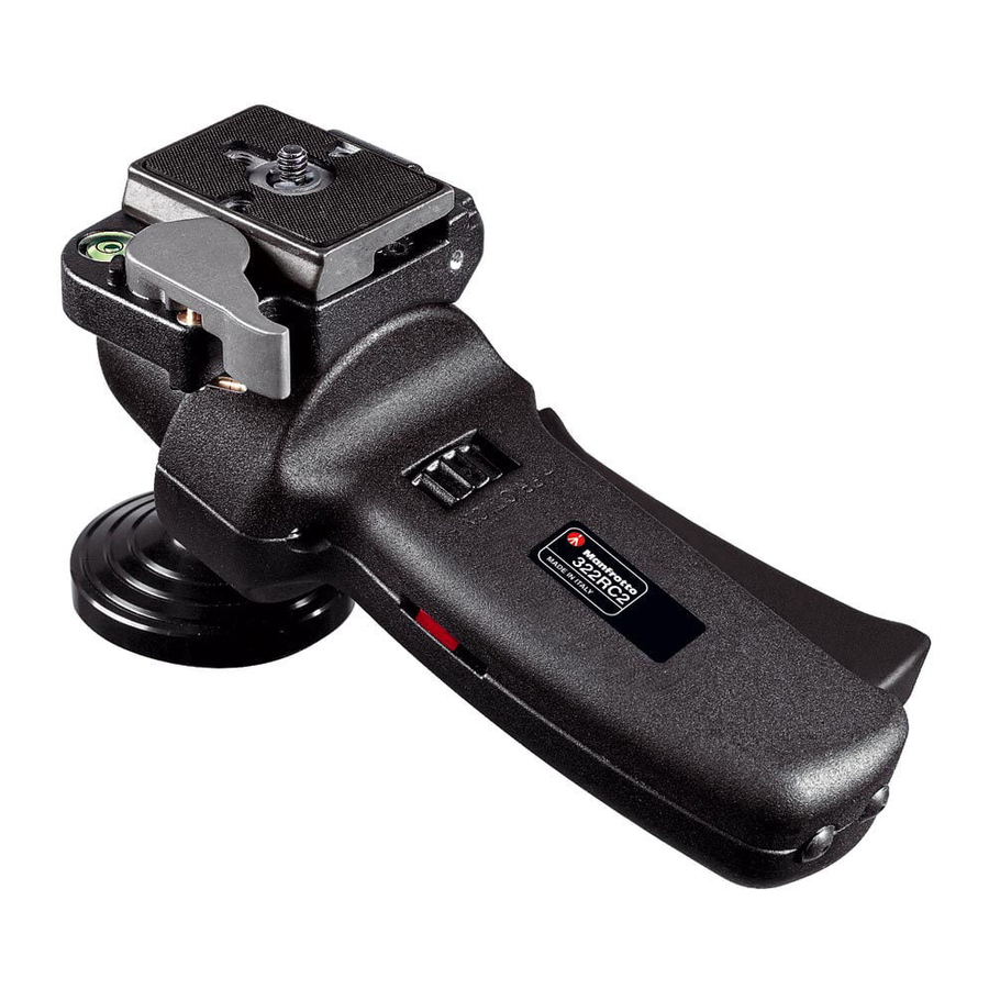
INTRODUCTION
Photographic ball head ideal for use with 35mm cameras with short or medium focal length lenses - ideal for action shots.
KEY FEATURES
- single lever for quick control of all movements
- quick release plate with built-in secondary safety pin
- built-in bubble spirit level
- friction control adjustable for different camera weights
- customisable for left or right handed use, in vertical or horizontal position
SET UP
Fix the 322RC2 head to your tripod via the 3/8" female thread "A". In order to fix the head securely, insert a screwdriver (or similar long lever) into hole "B" and use it to exert more leverage to lock the head tightly to the tripod.

 The top plate on Manfrotto tripods is equipped with three screws "C" which tighten against the base of the head to ensure even more effective and secure locking.
CUSTOMISING THE POSITION OF THE DEVICE
The 322RC2 allows you to customise the position of the camera plate to suit your ideal working position whether you're right- or left-handed, and whether you prefer to use the head horizontally or vertically.
Right handed – horizontal position
The 322RC2 head is factory-assembled in this position. You do not need to adjust anything to use the head in this configuration
Left handed – horizontal position
To configure the head for left-handed use in the horizontal position, you need to remove the quick release plate assembly from the body of the 322RC2, and then reattach it in the correct location.
- To remove quick release plate "G" (fig 2), first open lever "H". This can not be opened while the secondary safety pin "I" is in the closed position. To release the safety catch, rotate the safety pin "I" fully in the direction of the arrow. Pull back lever "H" until peg "L" clicks up and holds "H" open.
Now use supplied allen key "W" (fig. 2) to loosen screws "K" and remove the base plate.

- Move the head grip into the correct position for left-handed use by squeezing trigger "D" and turning the whole grip around to the left of the centre ball and then "upside down" so that the trigger is facing away from you as shown in fig. 3.

- Remove the screw hole plugs "Z"
- Position the base plate above the head so that the grey camera plate locking lever is on the opposite side of the head from the trigger. Fix the base plate in position using the allen key "W" to tighten screws "K" into the threaded holes "X" on the left.


Vertical position
To configure the head for left- or right-handed use in the vertical position, you need to remove the quick release plate assembly from the body of the 322RC2, and then reattach it in the correct location.
- To remove quick release plate "G" (fig 2), firstopen lever "H". This can not be opened while the secondary safety pin "I" is in the closed position. To release the safety catch, rotate the safety pin "I" fully in the direction of the arrow. Pull back lever "H" until peg "L" clicks up and holds "H" open. Now use supplied allen key "W" (fig. 2) to loosen screws "K" and remove the base plate.
- Move the head grip into the vertical as shown in figure 4.

- Remove the screw hole plugs "Z"
- Position the base plate above the head so thatthe grey camera plate locking lever is on the opposite side of the head from the trigger. Fix the base plate in position using the allen key "W" to tighten screws "K" into the centrally-located threaded holes "J".

CUSTOMISING THE DEVICE HEAD FOR USE WITH TELE LENSES FITTED WITH TRIPOD ATTACHMENT BRACKETS
It may be useful (or even essential) to change the position of the 322RC2's camera plate assembly if you intend to use the head with a tele lens fitted with a tripod attachment bracket. If you find that the camera body hanging behind the tele lens stops you from using the grey quick release plate lever "H" (and therefore prevents you from fixing or releasing your camera) you should turn the whole plate assembly round 180° so that the grey quick release plate lever "H" is on the same side of the head as the main trigger:

- To remove quick release plate "G" (fig 2), firstopen lever "H". This can not be opened while the secondary safety pin "I" is in the closed position. To release the safety catch, rotate the safety pin "I" fully in the direction of the arrow. Pull back lever "H" until peg "L" clicks up and holds "H" open. Now use supplied allen key "W" (fig. 2) to loosen screws "K" and remove the base plate.
- Turn the base plate round 180° and position itabove the head so that the grey camera plate locking lever is on the same side of the head as the trigger. Fix the base plate in position using the allen key "W" to tighten screws "K" into the threaded holes "V".
REMOVING THE QUICK RELEASE PLATE FROM HEAD

To remove quick release plate "G" (fig 2), first open lever "H". This can not be opened while the secondary safety pin "I" is in the closed position. To release the safety catch, rotate the safety pin "I" fully in the direction of the arrow. Pull back lever "H" until peg "L" clicks up and holds "H" open.
FIXING THE CAMERA TO THE PLATE
Attach the plate "G" to your camera or lens (if you're using a tele lens with tripod bracket) by fastening screw "M" into the camera/lens threaded hole. Ensure that the camera/lens is aligned in the direction shown by the arrow marked "LENS" on the underside of plate "G". For secure attachment, tighten using ring "Q" WITHOUT APPLYING EXCESSIVE FORCE.

Ensure your camera is securely locked to the release plate before use
MOUNTING THE CAMERA ON THE HEAD
Push ring "Q" (fig. 7) down so that it lies flat against plate "G". Insert camera plate "G" (fig. 8) so the uncontoured back edge "Z" (see also fig. 7) fits against the locking lever "H" on top of the head. Push down the camera and plate "G" until locking lever "H" clicks shut.

Secure attachment of your camera to the 322RC2 head can only be achieved by fitting the camera plate into the base plate in the correct orientation as described above!
Make sure that plate "G"(fig. 9) is fully locked by pushing the grey quick release lever hard against the camera plate. Finally, rotate the secondary safety lever "I" clockwise so that it pops up and stops the grey quick release lever from coming open accidentally.

REMOVING THE CAMERA FROM THE HEAD

To remove the camera from the head, disengage the secondary safety lock "I", hold the camera securely in one hand, and then pull back the grey quick release lever "H" with the other. Lift the camera up and backwards off the head.
USING THE HEAD
All camera movements are controlled by using the grip handle "D" (fig. 1). Squeezing the large trigger at the front of grip handle "D" releases the locking mechanism and allows the head to move, following the movements of your hand/wrist. Release the trigger again to blocks the head in the required position.
The 322RC2 has an adjustable friction control (ring "F" – fig. 11) which sets how firmly the ball is gripped by the locking mechanism. Rotate the ring "F" in the direction of the "+" symbol to increase friction; rotate it in the direction of the "–" symbol to decrease friction.
Friction level is shown by index "N".
The 322RC2 also has a bubble spirit level (fig. 11) to help you get your camera level with the horizon. It can be extracted from its standard position (if it doesn't come out easily, try gently using a pair of pliers) and inserted in the opposite side of the head if you are using the 322RC2 in its lefthanded configuration.

MAINTENANCE
After extended use you may notice that the ball locking mechanism becomes slightly more slack. You can re-adjust this by tightening screw "R" very slightly using the supplied allen key "W". Only small adjustments are necessary to regain full locking power.
The 322RC2 head can be fitted with the optional shutter release (mod. 322RS, 322RSM) to control the camera while moving your head.


Documents / ResourcesDownload manual
Here you can download full pdf version of manual, it may contain additional safety instructions, warranty information, FCC rules, etc.
Advertisement
Thank you! Your question has been received!


Need Assistance?
Do you have a question about the 322RC2 that isn't answered in the manual? Leave your question here.