
Related Manuals for Panasonic NN-CF770M CPH


Summary of Contents for Panasonic NN-CF770M CPH
- Page 1 ORDER NO.PHAMOS1007054C7 Microwave Oven NN-CF770M CPH (CANADA) RPH (MEXICO & LATIN AMERICA) © Panasonic Home Appliances Microwave Oven (Shanghai) Co., Ltd. 2010.
- Page 2 NN-CF770M...
- Page 3 NN-CF770M...
-
Page 4: Table Of Contents
NN-CF770M CONTENTS Page Page 1 FEATURE CHART 7.2. Monitor Interlock Switch 2 CONTROL PANEL 7.3. Magnetron 3 SCHEMATIC DIAGRAM 7.4. Inverter power supply (U) 3.1. CPH 7.5. Temperature thermistor 3.2. RPH 8 MEASUREMENTS AND ADJUSTMENTS 4 DESCRIPTION OF OPERATING SEQUENCE 8.1. -
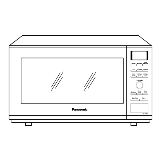
Page 5: Feature Chart
NN-CF770M 1 FEATURE CHART 2 CONTROL PANEL... -
Page 6: Schematic Diagram
NN-CF770M 3 SCHEMATIC DIAGRAM 3.1. -
Page 7: Rph
NN-CF770M 3.2. -
Page 8: Description Of Operating Sequence
NN-CF770M 4 DESCRIPTION OF OPERATING SEQUENCE 4.1. Variable power cooking 4.3. Auto Menu cooking control When the Auto Menu feature is selected and the [Start] button is tapped: High Voltage Inverter Power Supply (U) controls output power 1. The digital programer circuit determines the power level and by the signal from Digital Programmer Circuit (D.P.C.). -
Page 9: Convection Cooking Control
NN-CF770M 4.6. Convection cooking control The digital programmer circuit controls the ON-OFF time of the heater in order to control oven cavity temperature. 1. After selecting desired oven cavity temperature Convection/Grill Convection (the range of selected oven temp is 100°C-250°C) and pressing [Start] button, a high level signal comes out of the micro computer and applies to power relay (RY6). -
Page 10: Cautions To Be Observed When Troubleshooting
NN-CF770M 5 CAUTIONS TO BE OBSERVED WHEN TROUBLESHOOTING Unlike many other appliances, the microwave oven is a high voltage, high current device. It is free from danger in ordinary use, though extreme care should be taken during repair. CAUTION Servicemen should remove their watches & rings whenever working close to or replacing the magnetron. -
Page 11: Part Replacement
NN-CF770M 5.6. Verification after repair Discharging the high voltage capacitors WARNING 1. After repair or replacement of parts, make sure that the There is high voltage present with high current capabilities screws of the oven, etc. are neither loosen or missing. in the circuits of the primary and secondary windings, choke Microwave energy might leak if screws are not properly coil and heat sinkof the inverter. -
Page 12: Disassembly And Parts Replacement Procedure
NN-CF770M 6 DISASSEMBLY AND PARTS REPLACEMENT PROCEDURE 6.1. Inverter power supply 5. Release locking tabs connecting inverter air guide with inverter bracket. CAUTIONS 6. Remove 1 screw holding H.V.Inverter to Inverter bracket. 1. Always leave the grounding plate in place. 2. -
Page 13: Magnetron
NN-CF770M 6.3. Digital programmer circuit 6.2. Magnetron (D.P.C) & Membrane Sheet 1. Steps same as disassembly of H.V. Inverter step 1 to step NOTE: 2. Remove 1 screw holding thermistor on magnetron. Be sure to ground any static electric charge built up on your body before handling the D.P.C. - Page 14 NN-CF770M 3. Remove 2 screws holding D.P.C. board DU (Relay board). 6. Separate D.P.C board from tabs on the escutcheon base and remove D.P.C board. To replace membrane key board 7. Use tools such as kinfe etc. to lift the edge of membrane sheet and peel off escutcheon sheet &...
-
Page 15: Low Voltage Transformer And/Or Power Relays (Ry1, Ry2, Ry4, Ry5, Ry6, Ry7)
NN-CF770M 6.4. Low voltage transformer 6.5. Fan motor and/or power relays (RY1, 1. Disconnect 2 lead wires from fan motor terminals. RY2, RY4, RY5, RY6, RY7) 2. Remove 4 screws holding inverter reinforcement bracket A on right heater panel & base plate respectively. NOTE: Be sure to ground any static electric charge built up on your body before handling the D.P.C. -
Page 16: Quartz Heater
NN-CF770M 6.7. Door assembly 6.6. Quartz heater 1. Remove door C from door E by carefully pulling outward, 1. Disconnect lead wires from heater terminals. starting from upper right hand corner using a flat blade 2. Remove 2 screws holding heater mounting plate from the screwdriver. -
Page 17: Stirrer Motor
NN-CF770M 6.8. Stirrer motor 1. Remove the motor cover by breaking off at the 8 spots indicated by arrows with a cutter or the like. 6.9. Convection fan motor and convection heater 1. Remove 1 screw holding side cover on cavity back plate. NOTE: After removing the motor cover, be sure that cut portions are properly trimmed or bent to the inside... - Page 18 NN-CF770M 4. Remove 1 screw holding back cover on the lower of back plate, then remove back cover. To replace convection heater 7. Remove 1 nut holding convection fan, then remove 5. Disconnect 2 lead wires from thermal cutout and convection convection fan.
- Page 19 NN-CF770M 9. Remove 1 screw holding heater bracket A on convection inside cover A. 10. Remove 2 screws holding convection heater on convection inside cover A. To replace convection motor 11. Remove 2 screws holding convection motor on convection fan bracket.
-
Page 20: Component Test Procedure
NN-CF770M 7 COMPONENT TEST PROCEDURE 7.3. Magnetron WARNING 1. High voltage is present at the output terminals of the High Voltage Inverter (U) including aluminum heat sink during any cook cycle. Continuity checks can only indicate an open filament or a 2. -
Page 21: Inverter Power Supply (U)
NN-CF770M 7.4. Inverter power supply (U) 5. Program oven at High power for 1 minute and press [Start] button. DO NOT try to REPAIR H.V. Inverter power supply a. After approximately 3 seconds, oven stops operating. (U).Replace complete H.V. Inverter(U) Unit. b. -
Page 22: Measurements And Adjustments
NN-CF770M 8 MEASUREMENTS AND ADJUSTMENTS 8.1. Adjustment of primary latch switch, secondary latch switch and monitor interlock switch. 1. Mount the Primary latch switch, the Secondary latch switch and the Monitor interlock switch to the door hook assembly as shown in illustration. NOTE: 8.2. -
Page 23: Procedure For Measuring Microwave Energy Leakage
NN-CF770M 9 PROCEDURE FOR MEASURING MICROWAVE ENERGY LEAKAGE 9.2.1. Measurement with the outer panel removed. Whenever you replace the magnetron, measure for radiation leakage before the outer panel is installed and after all necessary components are replaced or adjusted. Special care should be taken in measuring around the magnetron. -
Page 24: At Least Once A Year, Have The Radiation Monitor Checked For Calibration By Its Manufacturer
NN-CF770M 9.4. At least once a year, have the radiation monitor checked for calibration by its manufacturer. -
Page 25: Troubleshooting Guide
NN-CF770M 10 TROUBLESHOOTING GUIDE DANGER: HIGH VOLTAGES 1. DO NOT RE-ADJUST PRESET CONTROL on the H.V.Inverter (U). It is very dangerous to repair or adjust without proper test equipment because this circuit generates very large current and high voltage. Operating a misaligned inverter circuit is dangerous. 2. -
Page 26: Troubleshooting) Oven Stops Operation During Cooking
NN-CF770M 10.1. (Troubleshooting) Oven stops operation during cooking SYMPTOM CAUSE CORRECTIONS 1. Oven stops in 3 seconds after No input AC is supplied to H.V.Inverter (U) 1. Latch Switch pressing [Start] button. CN702 terminals 2. Power relay RY1 3. Loose lead wire connector CN701, CN702 4. -
Page 27: Troubleshooting) Other Problems
NN-CF770M 10.2. (Troubleshooting) Other problems SYMPTOM CAUSE CORRECTIONS 1. Oven is dead. 1. Open or loose lead wire harness Fuse is OK. 2. Open thermal cutout / thermistor Check thermal cutout is defective. No display and no operation at all. 3. -
Page 28: Troubleshooting Of Inverter Circuit (U) And Magnetron
NN-CF770M 10.3. Troubleshooting of inverter circuit (U) and magnetron This oven is programmed with a self diagnostics failure code system which will help for troubleshooting. H95, H97, H98 and H99 are the provided failure codes to indicate magnetron and inverter circuit problem areas. This section explains failure codes of H95, H97, H98 and H99. -
Page 29: Trouble Related To Digital Programmer Circuit
NN-CF770M 10.4. Trouble related to Digital Programmer Circuit SYMPTOM STEP CHECK RESULT CAUSE/CORRECTIONS No display when oven is first plugged Fuse pattern of D.P.C. Normal →Step2 Open Replace D.P.C., L.V.T. or Fuse Pattern IC10 pin4 voltage Abnormal 0V L.V.T. →Step3 Normal=18V IC1 pin9 voltage Abnormal... -
Page 30: Simple Way Of H.v. Inverter/Magnetron Troubleshooting
NN-CF770M 10.5. SIMPLE WAY OF H.V. INVERTER/MAGNETRON TROUBLESHOOTING Purpose: Simple way (3/23 seconds rule) of identifying whether it’s Magnetron, Inverter or others. Set-up: The unit under question is connected through the Ammeter as shown below. Procedure: Follow the matrix table below to identify the problem source. Note: Do not replace both Inverter board and Magnetron simultaneously and automatically without going through this procedure. -
Page 31: How To Check The Semiconductors Using An Ohm Meter
NN-CF770M 10.7. How to check the semiconductors using an OHM meter... -
Page 32: Exploded View And Parts List
NN-CF770M 11 EXPLODED VIEW AND PARTS LIST 11.1. EXPLODED VIEW... -
Page 33: Parts List
NN-CF770M 11.2. PARTS LIST NOTE: 1. When ordering replacement part(s), please use part number(s) shown in this part list. Do not use description of the part. 2. Important safety notice: Components identified by mark have special characteristics important for safety. When replacing any of these components, use only manufacture’s specified parts. - Page 34 NN-CF770M Ref. No. Part No. Part Name & Description Pcs/Set Remarks F10589M60BP SIDE COVER F40307Q70BP AIR GUIDE D F64609M50QP HEATER MOUNTING PLATE F22397Q70BP CONVECTION FAN BLADE F41594V00BP COOLING FAN BLADE F41809M60BP CONVECTION FAN BRACKET F490S9M80CP CONVECTION FAN MOTOR F631D9M80CP CONVECTION HEATER F64174V00BP HEATER BRACKET A F66797Q70BP...
-
Page 35: Escutcheon Base Assembly
NN-CF770M 11.3. ESCUTCHEON BASE ASSEMBLY Ref. No. Part No. Part Name & Description Pcs/Set Remarks F603L9M80CP D.P.CIRCUIT (AU) F603L9M80RP D.P.CIRCUIT (AU) F603Y9M80CP D.P.CIRCUIT (DU) F83379M80SCP MEMBRANE SHEET F83379M80SRP MEMBRANE SHEET F80349M60SBP ESCUTCHEON BASE F891P9L60KXP DOOR OPENING BUTTON (U) F80375K00AP COOK BUTTON SPRING F82569M60BP DOOR OPENING LEVER F80579M60BBP... -
Page 36: Door Assembly
NN-CF770M 11.4. DOOR ASSEMBLY Ref. No. Part No. Part Name & Description Pcs/Set Remarks F30186P40AG DOOR KEY A F302A9M50SQP DOOR A (U) F301P9M60BP DOOR E (U) F30215G10XN DOOR KEY SPRING F30859Q30AP DOOR C F04114180CP HC LABEL F02459660AP DHHS LABEL... -
Page 37: Wiring Materials
NN-CF770M 11.5. WIRING MATERIALS Ref. No. Part No. Part Name & Description Pcs/Set Remarks F030A9M80CP LEAD WIRE HARNESS (INCLUDING OVEN TEMP SENSOR & MAGNETRON THERMISTOR) F030E-1P00 H.V.LEAD WIRE... -
Page 38: Packing And Accessories
NN-CF770M 11.6. PACKING AND ACCESSORIES Ref. No. Part No. Part Name & Description Pcs/Set Remarks F00039M80CP INSTRUCTION MANUAL F00039M80RP INSTRUCTION MANUAL F01029M80SCP PACKING CASE,PAPER F01029M80SRP PACKING CASE,PAPER F01049M60BP UPPER FILLER F01059M60BP LOWER FILLER F01066Y40XP P.E.BAG F01078100XN DOOR SHEET F060V9M60QP WIRE RACK F06037J70XP ENAMEL SHELF F01089M50QP... -
Page 39: Digital Programmer Circuit
NN-CF770M 12 DIGITAL PROGRAMMER CIRCUIT 12.1. SCHEMATIC DIAGRAM... - Page 40 NN-CF770M...
-
Page 41: Parts List
NN-CF770M 12.2. PARTS LIST Ref. No. Part No. Part Name & Description Pcs/Set Remarks BZ310 L0DDEA000014 BUZZER 2.0KHz C584 F2A1C100B624 CHEM CAPACITOR 10µF/16V F2A1H471B551 AL CHEM CAPACITOR 470µF/35V F2A1C220B624 AL CHEM CAPACITOR 22µF/16V C225 F1B3A102A049 CERAMIC CAPACITOR CX320 H2A8004A0038 CERAMIC RESONATOR 8.0MHz DISP110 L5AYAYY00058...