
Related Manuals for Toshiba RBM-SV1121HUPE


Summary of Contents for Toshiba RBM-SV1121HUPE
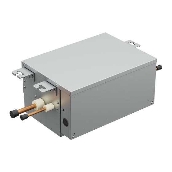
- Page 1 Installation Manual Shut-off Valve unit RBM-SV1121HUPE RBM-SV1801HUPE RBM-SV6701HUPE English...
-
Page 2: Table Of Contents
Thank you very much for purchasing TOSHIBA Super Heat Recovery Multi Advance (SHRM-A) Air conditioner. Please read this manual carefully before using your Shut-off Valve unit. When installing an indoor or outdoor unit, follow the Installation Manual supplied with the unit. -
Page 3: Accessory Parts And Parts To Be Procured Locally
PRECAUTIONS FOR SAFETY Accessory parts and Parts to be procured locally Accessory parts ■ • Ensure that all Local, National and International regulations are satisfi ed. Q’ty RBM- Part name Shape Usage SV1121HUPE SV1801HUPE SV6701HUPE • Read this “PRECAUTIONS FOR SAFETY” carefully before This manual for installer. - Page 4 *2: Slight injury indicates injury, burns, electric shock, and other WARNING injuries which do not require hospitalization or long-term • Ask an authorized dealer or qualifi ed installation treatment as an outpatient. professional to install/maintain the air conditioner. *3: Damage to property indicates damage extending to buildings, Inappropriate installation may result in water leakage, electric household effects, domestic livestock, and pets.
- Page 5 • Install the air conditioner securely in a location where the CAUTION base can sustain the weight adequately. This Air Conditioner has adopted a refrigerant HFC (R32) • Perform the specifi ed installation work to guard against an which does not destroy the ozone layer. earthquake.
-
Page 6: Selection Of Installation Place
SELECTION OF INSTALLATION PLACE Installation under high-humidity atmosphere In some cases including the rainy season, especially inside of the ceiling may become high-humidity atmosphere. 1. Installation to inside of the ceiling with tiles on the roof Please refer from safety device from Outdoor unit Installation manual. 2. -
Page 7: Installation Of Shut-Off Valve Unit
INSTALLATION OF SHUT-OFF VALVE <Installation space> UNIT (Unit : mm) Bolt size : M10 or Ø3/8 (field supply) WARNING 100 or more Install the unit securely in the place to suffi ciently withstand the weight of the unit. RBM-*** If the foundation is not sturdy enough, the unit may fall and cause personal injury. SV1121HUPE 250 ( 1) Perform a specifi ed installation work to guard against earthquake. - Page 8 Refrigerant pipe connection port (Pipe hanging bracket) outdoor unit side indoor unit side anchor bolt) Control Box Steel frame structure RBM-SV1121HUPE Use existing angles or install new support angles. RBM-SV1801HUPE Hanging bolt (Unit external dimension) (Hanging bolt pitch) (Hanging bolt Power supply wire intake port (Ø20)
-
Page 9: Installation Of Battery Kit
■ • Refer to the Installation Manual of the outdoor unit for details. • Do not connect anything except TOSHIBA Battery kit. This kit includes a nickel-metal hydride battery (NiMH). For your safety, please read Instruction Manual in WARNING •... - Page 10 For airtight test, air purge, addition of refrigerant, and gas leak check, follow the Installation Manual attached to Use attached-pipe (accessory) to connect the pipe with different diameter from the pipe to Shut-off Valve unit. • the outdoor unit. (RBM-SV1121HUPE, RBM-SV6701HUPE) REQUIREMENT RBM-SV1121HUPE RBM-SV1801HUPE Be sure to use the tool such as charge hose exclusive to R32 or R410A.
-
Page 11: Electrical Connection
ELECTRICAL CONNECTION U1 U2 U1 U2 U1 U2 Indoor unit CAUTION If incorrect / incomplete wiring is carried out, it will cause an electrical fi re or smoke. Use the cord clamps attached to the product. Do not damage or scratch the conductive core and inner insulator of power and communication wires when peeling them. - Page 12 Earth screw Cable clamp Power supply terminal block Screw (Accessory) Clamp filter (Accessory) Electrical control box cover RBM-SV1121HUPE RBM-SV1801HUPE 2 turn Communication wire It’s possible to come out the communication wires on the right side. terminal block Communication wire Communication wire...
- Page 13 50 (SV1121HUPE, SV1801HUPE) 220 (SV6701HUPE) Earth wire Power supply wire See the fi gure on the left for connecting wires to the terminal. Communication wire Communication wires Communication wiring Terminal block for remote controller wiring of indoor unit Shut-off Valve unit terminal on PCB Communication wires (locally procured)
- Page 14 1145012599-1...