
Related Manuals for Siemens SINAMICS SIMOTICS S200 PROFINET


Summary of Contents for Siemens SINAMICS SIMOTICS S200 PROFINET
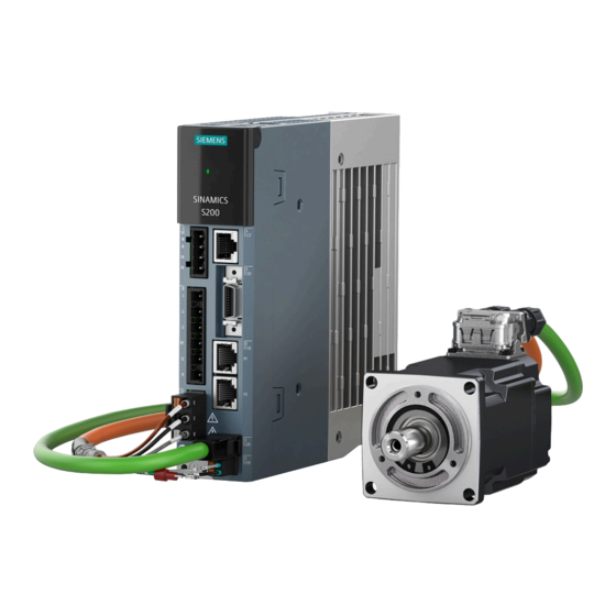
- Page 1 Edition 11/2023 OPERATING INSTRUCTIONS SINAMICS/SIMOTICS SINAMICS S200 PROFINET servo drive system SINAMICS S200 converter product line, PROFINET version (PN) SIMOTICS S-1FL2 servo motor www.siemens.com/drives...
- Page 3 Introduction Fundamental safety instructions Description SINAMICS/SIMOTICS Application planning SINAMICS S200 PROFINET servo Mounting drive system with SIMOTICS S-1FL2 Connecting Operating Instructions Commissioning (web server) Commissioning (Startdrive) Series commissioning Functions Tuning System messages Corrective maintenance Technical data PROFINET version (PN), Firmware V6.3 Examples/applications Appendix 11/2023, FW V6.3...
- Page 4 Note the following: WARNING Siemens products may only be used for the applications described in the catalog and in the relevant technical documentation. If products and components from other manufacturers are used, these must be recommended or approved by Siemens. Proper transport, storage, installation, assembly, commissioning, operation and maintenance are required to ensure that the products operate safely and without any problems.
-
Page 5: Table Of Contents
Use of third-party products in this documentation .............. 18 1.2.6 Websites of third-party companies..................18 SINAMICS documentation ....................19 Service and Support......................20 1.4.1 Siemens Industry Online Support on the Web..............20 1.4.2 Spare parts services ......................20 Important product information ..................21 1.5.1 Intended use........................21 1.5.2... - Page 6 Table of contents 3.2.3.1 Overview ........................... 54 3.2.3.2 Article number explanation....................55 Device combinations......................56 3.3.1 200 V servo drive system ....................56 3.3.2 400 V servo drive system ....................57 Accessories ........................59 3.4.1 Connector kits ........................59 3.4.2 Cables and connectors .......................
- Page 7 Table of contents Mounting ............................. 99 Converter .......................... 99 5.1.1 Mounting instructions for the converter ................99 5.1.2 Mounting position ......................99 5.1.3 Dimension drawings and drilling dimensions..............100 5.1.3.1 Dimension drawing and drilling dimensions for the 200 V converter ......... 100 5.1.3.2 Dimension drawing and drilling dimensions for the 400 V converter .........
- Page 8 Table of contents 6.5.4.2 Interface description (motor side) ..................144 6.5.4.3 Wiring ..........................145 6.5.5 Rotating the connectors at the motor ................145 Connecting the braking resistor..................148 6.6.1 Interface description - X1 ....................148 6.6.2 Wiring ..........................148 Connecting the 24 V DC power supply................151 6.7.1 Interface description - X124 .....................
- Page 9 Table of contents 7.4.3.2 Inputs/outputs ......................... 188 7.4.4 Diagnostics ........................188 7.4.4.1 Messages......................... 188 7.4.4.2 Diagnostic buffer ......................191 7.4.4.3 Safety Integrated (for S200 PN only)................. 192 7.4.4.4 Connection overview ....................... 193 7.4.4.5 Communication ....................... 193 7.4.4.6 Status word and control word ..................195 7.4.5 Parameters ........................
- Page 10 Table of contents 8.5.1.4 Specifying a motor......................241 8.5.2 Control and technology object ..................243 8.5.2.1 Inserting a SIMATIC S7 controller into the project.............. 243 8.5.2.2 Networking a controller and a converter................245 8.5.2.3 Inserting a technology object into the SIMATIC S7 controller ..........247 8.5.2.4 Interconnecting the technology object and a converter.............
- Page 11 Table of contents 8.9.6.3 Setting the time with synchronization (NTP server)............303 8.9.6.4 Setting the time with synchronization (PLC as NTP server) ..........304 8.9.6.5 Setting the time without synchronization ................. 304 8.9.7 Backup and restore ......................305 8.9.7.1 Restarting the drive......................305 8.9.7.2 Retentively saving the drive data ..................
- Page 12 Table of contents 10.4.6.3 Control and status word for encoder 1................349 10.4.6.4 Control word for block selection ..................350 10.4.6.5 Control word for MDI mode....................351 10.4.6.6 Control and status word 1 for the positioner..............352 10.4.6.7 Control and status word 2 for the positioner..............354 10.4.6.8 Message word .........................
- Page 13 Table of contents 10.7.7.2 Fail-safe acknowledgement of safety messages ..............407 10.7.8 Response time ......................... 408 10.7.9 Functional safety ......................408 10.7.10 Machinery Directive ......................409 Tuning ..............................411 11.1 Tuning workflow......................411 11.2 Autotuning ........................412 11.2.1 One Button Tuning......................412 11.2.2 Real Time Tuning (Online Tuning)..................
- Page 14 Table of contents 13.4 Device disposal ........................ 608 Technical data............................ 609 14.1 Technical data of the converter ..................609 14.1.1 Permissible environmental conditions for the converter ............ 609 14.1.2 General technical data ..................... 610 14.1.3 Specific data of the 200 V converters................612 14.1.4 Specific data of the 400 V converters................
- Page 15 Table of contents 14.2.14.20 1FL2203-4AF connected to 3 AC 380 V/3 AC 400 V............664 14.2.14.21 1FL2204-2AF connected to 3 AC 380 V/3 AC 400 V............665 14.2.14.22 1FL2204-4AF connected to 3 AC 380 V/3 AC 400 V............666 14.2.14.23 1FL2205-2AF connected to 3 AC 380 V/3 AC 400 V............667 14.2.14.24 1FL2205-4AF connected to 3 AC 380 V/3 AC 400 V............
- Page 16 Table of contents SINAMICS S200 PROFINET servo drive system with SIMOTICS S-1FL2 Operating Instructions, 11/2023, FW V6.3, A5E51646752B AB...
-
Page 17: Introduction
With the SINAMICS converter series you can solve drive tasks in the low, medium and DC voltage range. All Siemens drive components, such as converters, motors, and controls, are matched to each other and can be integrated into your existing automation systems. -
Page 18: About This Manual
Unless explicitly contractually agreed, Siemens assumes no liability for such suitability. Suitability for a particular application in specific individual cases must be assessed by the user, taking into account all technical, legal, and other requirements on a case-by-case basis. -
Page 19: What's New
Introduction 1.2 About this manual 1.2.3 What's new? Description Changes with respect to Edition 07/2023 • Updated the converter firmware to V6.3 • Updated the rating plate example for 1FL2 motors, shaft heights 20 and 30 Rating plate (Page 50) • Updated the serial number explanation for 1FL2 motors Serial number explanation (Page 53) •... -
Page 20: Use Of Third-Party Products In This Documentation
This document may contain hyperlinks to third-party websites. Siemens is not responsible for and shall not be liable for these websites and their content. Siemens has no control over the information which appears on these websites and is not responsible for the content and information provided there. -
Page 21: Sinamics Documentation
1.3 SINAMICS documentation SINAMICS documentation Description The documentation on the SINAMICS product series is available under Siemens Industry Online Support (https://support.industry.siemens.com/cs/ww/en/view/109807358). You can display documents or download them in PDF and HTML5 formats. The SINAMICS product documentation essentially includes the following manuals:... -
Page 22: Service And Support
1.4 Service and Support Service and Support 1.4.1 Siemens Industry Online Support on the Web Important product information is available through Siemens Industry Online Support using the following options: • Website: SIOS (https://support.industry.siemens.com/cs/ww/en/) • App Industry Online Support (for Apple iOS and Android) Content of Siemens Online Support •... -
Page 23: Important Product Information
Introduction 1.5 Important product information Important product information 1.5.1 Intended use Requirement WARNING Death or serious injury if not used as intended Not using as intended can result in hazardous states. • Carefully observe the description of intended use. WARNING Incorrect use of the motor Incorrect use of the motor may cause death, serious injury (crushing) and/or property damage. -
Page 24: Firmware Updates And Constraints
Firmware updates and constraints Description Firmware updates and constraints for the converters with the current firmware are available in SIOS: Updates and constraints for SINAMICS S200 (https://support.industry.siemens.com/cs/ww/en/ view/109812409) 1.5.3 Open-source software (OSS) Description The license conditions and copyright information of the open-source software components used by the device are saved on the device itself. -
Page 25: Compliance With The General Data Protection Regulation
1.5.4 Compliance with the General Data Protection Regulation Description Siemens complies with the principles of the General Data Protection Regulation (EU), in particular the principle of data minimization (privacy by design). For this SINAMICS product, this means: • User management and access control (UMAC) The product processes or stores the following personal data: –... - Page 26 Introduction 1.5 Important product information SINAMICS S200 PROFINET servo drive system with SIMOTICS S-1FL2 Operating Instructions, 11/2023, FW V6.3, A5E51646752B AB...
-
Page 27: Fundamental Safety Instructions
Fundamental safety instructions General safety instructions WARNING Electric shock and danger to life due to other energy sources Touching live components can result in death or severe injury. • Only work on electrical devices when you are qualified for this job. •... - Page 28 Fundamental safety instructions 2.1 General safety instructions WARNING Risk of electric shock and fire from supply networks with an excessively low impedance Excessively high short-circuit currents can lead to the protective devices not being able to interrupt these short-circuit currents and being destroyed, and thus causing electric shock or a fire.
- Page 29 Fundamental safety instructions 2.1 General safety instructions WARNING Electric shock due to unconnected cable shields Hazardous touch voltages can occur through capacitive cross-coupling due to unconnected cable shields. • As a minimum, connect cable shields and the cores of cables that are not used at one end at the grounded housing potential.
- Page 30 Fundamental safety instructions 2.1 General safety instructions WARNING Spread of fire from built-in devices Built-in devices can cause a fire and a pressure wave in the event of a fault. Fire and smoke can escape from the control cabinet and cause serious personal injury and property damage. •...
- Page 31 • Therefore, if you move closer than 20 cm to the components, be sure to switch off radio devices, cellphones or WLAN devices. • Use the "SIEMENS Industry Online Support App" or a QR code scanner only on equipment that has already been switched off.
- Page 32 Fundamental safety instructions 2.1 General safety instructions NOTICE Damage to motor insulation due to excessive voltages When operated on systems with grounded line conductors or in the event of a ground fault in the IT system, the motor insulation can be damaged by the higher voltage against ground. If you use motors that have insulation that is not designed for operation with grounded line conductors, you must perform the following measures: •...
- Page 33 Fundamental safety instructions 2.1 General safety instructions NOTICE Device damage caused by incorrect voltage/insulation tests Incorrect voltage/insulation tests can damage the device. • Before carrying out a voltage/insulation check of the system/machine, disconnect the devices as all converters and motors have been subject to a high voltage test by the manufacturer, and therefore it is not necessary to perform an additional test within the system/machine.
- Page 34 Fundamental safety instructions 2.1 General safety instructions WARNING Fire due to incorrect operation of the motor When incorrectly operated and in the case of a fault, the motor can overheat resulting in fire and smoke. This can result in severe injury or death. Further, excessively high temperatures destroy motor components and result in increased failures as well as shorter service lives of motors.
-
Page 35: Equipment Damage Due To Electric Fields Or Electrostatic Discharge
Fundamental safety instructions 2.2 Equipment damage due to electric fields or electrostatic discharge Equipment damage due to electric fields or electrostatic discharge Electrostatic sensitive devices (ESD) are individual components, integrated circuits, modules or devices that may be damaged by either electric fields or electrostatic discharge. NOTICE Equipment damage due to electric fields or electrostatic discharge Electric fields or electrostatic discharge can cause malfunctions through damaged individual... -
Page 36: Warranty And Liability For Application Examples
Fundamental safety instructions 2.3 Warranty and liability for application examples Warranty and liability for application examples Application examples are not binding and do not claim to be complete regarding configuration, equipment or any eventuality which may arise. Application examples do not represent specific customer solutions, but are only intended to provide support for typical tasks. -
Page 37: Cybersecurity Information
Siemens’ products and solutions undergo continuous development to make them more secure. Siemens strongly recommends that product updates are applied as soon as they are available and that the latest product versions are used. Use of product versions that are no longer supported, and failure to apply the latest updates may increase customer’s exposure... -
Page 38: Residual Risks Of Power Drive Systems
Fundamental safety instructions 2.5 Residual risks of power drive systems Residual risks of power drive systems When assessing the machine or system-related risk in accordance with the respective local regulations (e.g. EC Machinery Directive), the machine manufacturer or system integrator must take into account the following residual risks emanating from the control and drive components of a drive system: 1. - Page 39 Fundamental safety instructions 2.5 Residual risks of power drive systems 6. Influence of network-connected and wireless communications systems, e.g. ripple-control transmitters or data communication via the network or mobile radio, WLAN or Bluetooth. 7. Motors for use in potentially explosive areas: When moving components such as bearings become worn, this can cause enclosure components to exhibit unexpectedly high temperatures during operation, creating a hazard in areas with a potentially explosive atmosphere.
- Page 40 Fundamental safety instructions 2.5 Residual risks of power drive systems SINAMICS S200 PROFINET servo drive system with SIMOTICS S-1FL2 Operating Instructions, 11/2023, FW V6.3, A5E51646752B AB...
-
Page 41: Description
Description System overview Description The SINAMICS S200 servo drive system (PN version) is a single-axis servo drive system. It includes the following components tailored to one another: • SINAMICS S200 converter product line (PN version), which is available in the following two variants: –... - Page 42 Description 3.1 System overview ① Controller (for example, SIMATIC S7-1500) ② Communication between the converter and the controller via PROFINET ③ SINAMICS S200 converter product line (PN version) ④ Engineering via LAN with the web server in the converter ⑤ MOTION-CONNECT 350 or MOTION-CONNECT 380 cables for the motor power, the motor holding brake, and the encoder connections ⑥...
- Page 43 Description 3.1 System overview * The interfaces X131 and X108 are available on S200 PN only. For more information about the motor holding brake connection on S200 Basic PN, see Section "Connecting the motor holding brake (Page 139)". ① ⑧ Fuse or motor starter protector Shield clamp ②...
- Page 44 Description 3.1 System overview * The interfaces X131 and X108 are available on S200 PN only. For more information about the motor holding brake connection on S200 Basic PN, see Section "Connecting the motor holding brake (Page 139)". ① ⑧ Fuse or motor starter protector Shield clamp ②...
-
Page 45: Converter
Description 3.1 System overview More information For more information about the device combination, see Section "Device combinations (Page 56)". For more information about the interface connection, see Section "Connecting (Page 127)". 3.1.1 Converter Description The S200 converter product line (PN version) includes two converter variants: S200 Basic PN (200 V only) and S200 PN (200 V and 400 V). -
Page 46: Motor
Description 3.1 System overview 3.1.2 Motor Description The 1FL2 motor is intended for use with the S200 converter product line. The motor is available in the 200 V variant (low or medium inertia) and the 400 V variant (low, medium, or high inertia), and with different shaft heights. -
Page 47: Scope Of Delivery
Description 3.2 Scope of delivery Scope of delivery Description You must order the converter, motor, and cable components individually. 3.2.1 Converter Description The converter delivery includes at least the following components: • A ready‑to‑run converter with loaded firmware • A connector kit: –... -
Page 48: Rating Plate
Description 3.2 Scope of delivery 3.2.1.1 Rating plate Description The rating plate contains the article number and the technical data of the converter. Converter type Pollution degree and overvoltage category Article number Certifications Material number Country of origin Mains input Manufacturer's address Output data Note on disposal Supported motor rated power... -
Page 49: Article Number Explanation
Description 3.2 Scope of delivery 3.2.1.2 Article number explanation Description The following figure shows an explanation of the article number for the converter. Figure 3-5 Article number for the S200 converter product line SINAMICS S200 PROFINET servo drive system with SIMOTICS S-1FL2 Operating Instructions, 11/2023, FW V6.3, A5E51646752B AB... -
Page 50: Serial Number Explanation
Description 3.2 Scope of delivery 3.2.1.3 Serial number explanation Description SNC = Siemens Numerical Control Ltd., Nanjing Figure 3-6 Serial number for S200 converter product line SINAMICS S200 PROFINET servo drive system with SIMOTICS S-1FL2 Operating Instructions, 11/2023, FW V6.3, A5E51646752B AB... - Page 51 Description 3.2 Scope of delivery 3.2.2 Motor Description The 1FL2 motor is a servo motor with an integrated encoder and a high degree of protection. The motor delivery includes the following components: • A ready‑to‑run motor • A "Safety instructions" sheet •...
-
Page 52: Rating Plate
Description 3.2 Scope of delivery 3.2.2.1 Rating plate Description The rating plate contains the article number and the technical data of the motor. Article number Rated current I Cooling method according to EN 60034-6 16 Weight Motor ID Maximum speed n Certifications Rated speed n Manufacturer's address... - Page 53 Description 3.2 Scope of delivery Motor type Rated current I Article number Cooling method according to EN 60034-6 Serial number Motor ID Rated torque M Weight Static torque M Country of origin Rated voltage U Standard for all rotating electrical machines Rated power P Certifications Encoder type and resolution...
-
Page 54: Article Number Explanation
Description 3.2 Scope of delivery 3.2.2.2 Article number explanation Description The following figure shows an explanation of the article number for the motor. Figure 3-9 Article number for 1FL2 servo motors SINAMICS S200 PROFINET servo drive system with SIMOTICS S-1FL2 Operating Instructions, 11/2023, FW V6.3, A5E51646752B AB... -
Page 55: Serial Number Explanation
Description 3.2 Scope of delivery 3.2.2.3 Serial number explanation Description SNC = Siemens Numerical Control Ltd., Nanjing SMTJ = Siemens Mechatronics Technology JiangSu Ltd. Figure 3-10 Serial number for 1FL2 servo motors SINAMICS S200 PROFINET servo drive system with SIMOTICS S-1FL2... -
Page 56: Motion-Connect 350 And 380 Cables
Description 3.2 Scope of delivery 3.2.3 MOTION-CONNECT 350 and 380 cables 3.2.3.1 Overview Description The MOTION-CONNECT 350/380 cable delivery includes the following components: • The MOTION-CONNECT cable with assembled connectors for connecting the motor to the converter • A shield clamp for connection of the power cable to the shield plate of the converter •... -
Page 57: Article Number Explanation
Description 3.2 Scope of delivery 3.2.3.2 Article number explanation Description Table 3-3 Article numbers for MOTION-CONNECT 350 and 380 cables Description Position of the article number MOTION-CONNECT cables Cable variant MOTION-CONNECT 350 standard cable 5 ... -
Page 58: Device Combinations
Description 3.3 Device combinations Device combinations 3.3.1 200 V servo drive system Description Table 3-4 200 V servo drive system 1FL2 servo motors 200 V converters MOTION-CON‐ NECT prefabri‐ (S200 PN/S200 Basic PN) cated cables Rated Rated Rated Shaft Inertia Article number Article number Frame size Article number... -
Page 59: 400 V Servo Drive System
Description 3.3 Device combinations 3.3.2 400 V servo drive system Description Table 3-5 400 V servo drive system 1FL2 servo motors 400 V converters MOTION-CON‐ NECT prefabrica‐ (S200 PN only) ted cables Rated Rated Rated Shaft Inertia Article number Article num‐ Frame Article number torque... - Page 60 Description 3.3 Device combinations 1FL2 servo motors 400 V converters MOTION-CON‐ NECT prefabrica‐ (S200 PN only) ted cables Rated Rated Rated Shaft Inertia Article number Article num‐ Frame Article number torque power speed height size 1FL2 6FX3☐02- (Nm) (kW) (r/min) (mm) 6SL5510-1BE 1.27 3000...
-
Page 61: Accessories
Description 3.4 Accessories Accessories 3.4.1 Connector kits Description If you need new connectors used on the converter front panel, you can order connector kits from Siemens using the following article numbers. Converter Article number Illustration S200 PN 6SL5568-0XX00-0AA0 S200 Basic PN... -
Page 62: Cables And Connectors
MOTION-CONNECT cables and connectors Description Siemens recommends that you use MOTION-CONNECT prefabricated cable assemblies and connectors for connecting the motor to the converter. All Siemens cable assemblies and connectors are tested and compliant with CE standards and EMC requirements. Table 3-6... - Page 63 Note that Siemens does not provide any guarantee or warranty regarding the functionality, reliability or quality of non‑Siemens cables used with the S200 servo drive system, and is not responsible for device (e.g. motor and converter) damages due to the use of non-Siemens cables.
-
Page 64: I/O Cable And Connector
Description 3.4 Accessories Table 3-7 Overview of connectors and crimp contacts Cable connectors Article Description Connection type Quantity Illustration number per package 6FX2003- Connector 3HD00 Hybrid plug (drive end) Crimping 5 pieces/pack (connected to motor) 3HN00 Hybrid plug (non-drive end) Crimping 5 pieces/pack 0LL63 M17 circular connector... -
Page 65: Line Filter
IEC 61800-3 Category C2. Line filters are passive components used to expand the EMC properties of the servo drive system. Siemens recommends that you use a line filter to protect the system from high frequency noise. Note For applications in European Union, UK, and Korea, the use of the recommended line filters is mandatory to fulfill the local EMC directives. -
Page 66: Recommended Line Filters
Description 3.4 Accessories 3.4.3.1 Recommended line filters Table 3-9 Recommended line filters Converter frame size Rated current (A) Article number Degree of protection 1 AC, 200 V ... 240 V FSA/FSB/FSC 6SL5550-0XB21-8CA0 IP20 3 AC, 200 V ... 240 V FSA/FSB/FSC 6SL3203-0BE15-0VA0 IP20 3 AC, 380 V ... 480 V FSA/FSB 6SL5550-0XE20-5CA0 IP20... -
Page 67: Dimension Drawing
Description 3.4 Accessories 3.4.3.3 Dimension drawing 6SL5550-0XB21-8CA0 All dimensions are specified in millimeters. Tightening torque for the mounting screws: 2.5 Nm Tightening torque for the protective conductor fastening bolt: 2.0 Nm ... 2.2 Nm Tightening torque for the line-side and load-side screw connection: 0.7 Nm ... 0.8 Nm SINAMICS S200 PROFINET servo drive system with SIMOTICS S-1FL2 Operating Instructions, 11/2023, FW V6.3, A5E51646752B AB... - Page 68 Description 3.4 Accessories 6SL3203-0BE15-0VA0 and 6SL5550-0XE20-5CA0 All dimensions are specified in millimeters. Tightening torque for the mounting screws: 2.5 Nm Tightening torque for the protective conductor fastening bolt: 3.5 Nm ... 4.0 Nm Tightening torque for the line-side and load-side screw connection: 0.7 Nm ... 0.8 Nm SINAMICS S200 PROFINET servo drive system with SIMOTICS S-1FL2 Operating Instructions, 11/2023, FW V6.3, A5E51646752B AB...
- Page 69 Description 3.4 Accessories 6SL5550-0XE21-2CA0 All dimensions are specified in millimeters. Tightening torque for the mounting screws: 2.5 Nm Tightening torque for the protective conductor fastening bolt: 3.5 Nm ... 4.0 Nm Tightening torque for the line-side and load-side screw connection: 0.7 Nm ... 0.8 Nm SINAMICS S200 PROFINET servo drive system with SIMOTICS S-1FL2 Operating Instructions, 11/2023, FW V6.3, A5E51646752B AB...
- Page 70 Description 3.4 Accessories 6SL5550-0XE22-0CA0 All dimensions are specified in millimeters. Tightening torque for the mounting screws: 2.5 Nm Tightening torque for the protective conductor fastening bolt: 3.5 Nm ... 4.0 Nm Tightening torque for the line-side and load-side screw connection: 0.7 Nm ... 0.8 Nm SINAMICS S200 PROFINET servo drive system with SIMOTICS S-1FL2 Operating Instructions, 11/2023, FW V6.3, A5E51646752B AB...
-
Page 71: Mounting Instructions For The Line Filter
Description 3.4 Accessories 3.4.3.4 Mounting instructions for the line filter Description • Observe the requirements for "EMC-compliant installation (Page 92)" when mounting the line filter. • To achieve a low-impedance connection, mount the line filter on the same metallic mounting plate as the converter. Mount these two components as close as possible. Figure 3-11 Connecting the line filter (example) SINAMICS S200 PROFINET servo drive system with SIMOTICS S-1FL2... -
Page 72: External 24 V Dc Power Supply
Brake Note Siemens recommends that you use different 24 V DC power supplies for the converter and for the inductive loads such as relays or solenoid valves. If you use the 24 V DC power supply to supply both the inductive loads and the converter at the same time, make sure that you connect surge protection devices to the load side. -
Page 73: Shield Plate Kit
Description 3.4 Accessories Table 3-12 Replacement fans SINAMICS S200 PN Article number 3 AC, 380 V ... 480 V 6SL5560-0CE00-0AA0 6SL5560-0DE00-0AA0 3.4.6 Shield plate kit Description The shield plate kit (article number: 6SL5566-0AB00-0AA0) includes a shield plate and four fixing screws (M4 × 12). The shield plate can establish ground connections to both shielded cables and protective conductors. -
Page 74: Sd Card
The converter supports FAT32-format SD cards with a capacity of up to 32 GB. A permanently inserted SD card from Siemens is required to use functions that require a license. The license key can only be assigned to the Siemens SD card. -
Page 75: Directives And Standards
Description 3.5 Directives and standards Directives and standards 3.5.1 Directives, standards and certificates for the converter The following directives and standards are relevant for the converter: European Low Voltage Directive The converter fulfills the requirements stipulated in the Low-Voltage Directive 2014/35/EU, if it is covered by the application area of this directive. -
Page 76: Directives, Standards And Certificates For The Motor
Immunity to voltage drop of semiconductor process equipment The converter fulfills the requirements of the standard SEMI F47-0706. Quality systems Siemens AG employs a quality management system that meets the requirements of ISO 9001 and ISO 14001. Certificates for download You can find all relevant certificates for download on the Internet: Certificates (https://support.industry.siemens.com/cs/ww/en/ps/29596/cert) - Page 77 Internet: China RoHS (https://support.industry.siemens.com/cs/ww/en/ps/29685/cert) Quality systems Siemens AG employs a quality management system that meets the requirements of ISO 9001 and ISO 14001. China Energy Label The motors fulfill the China Energy Label Grade 2 according to GB 30253-2013.
-
Page 78: Directives, Standards And Certificates For The Motion-Connect Cable
As of the implementation date of the standard, all affected motors must be provided with the "China Energy Label". Affected Siemens products Affected Siemens motors are subject to the requirements of standard GB30253-2013: SIMOTICS S-1FL2 servo motors. Figure 3-13 Example of the China Energy Label ①... - Page 79 Internet: China RoHS (https://support.industry.siemens.com/cs/ww/en/ps/14662/cert) Quality systems Siemens AG employs a quality management system that meets the requirements of ISO 9001 and ISO 14001. Certificates for download You can find all relevant certificates for download on the Internet: Certificates (https://support.industry.siemens.com/cs/ww/en/ps/14662/cert)
- Page 80 Description 3.5 Directives and standards SINAMICS S200 PROFINET servo drive system with SIMOTICS S-1FL2 Operating Instructions, 11/2023, FW V6.3, A5E51646752B AB...
-
Page 81: Application Planning
Application planning Protection of persons from electromagnetic fields Overview Protection of workers from electromagnetic fields is specified in the European EMF Directive 2013/35/EU. This directive is implemented in national law in the European Economic Area (EEA). Employers are obligated to design workplaces in such a way that workers are protected from impermissibly strong electromagnetic fields. - Page 82 Application planning 4.1 Protection of persons from electromagnetic fields The indicated minimum distances apply to the head and complete torso of the human body. Shorter distances are possible for extremities. Table 4-1 Minimum distances to the converter Individuals without active implants Individuals with active implants Control cabinet closed Control cabinet open...
-
Page 83: Fault Protection For The Motor Circuit
More information You can find more information on the Internet: Manufacturer's declaration (https:// support.industry.siemens.com/cs/ww/en/view/109476638) SINAMICS S200 PROFINET servo drive system with SIMOTICS S-1FL2 Operating Instructions, 11/2023, FW V6.3, A5E51646752B AB... -
Page 84: Permissible Mains Supply Network Configurations For Motors
Application planning 4.3 Permissible mains supply network configurations for motors Permissible mains supply network configurations for motors Description In combination with the drive system, the motors are generally certified for operation on TN and TT line systems with grounded neutral point and on IT line systems. The following special features should be noted: •... -
Page 85: Line Connection Conditions For The Converter With The Motor 1Fl2
Application planning 4.4 Line connection conditions for the converter with the motor 1FL2 Line connection conditions for the converter with the motor 1FL2 Description The drive system is designed for connection to grounded TN/TT and non-grounded IT mains supply networks. Depending on the motor/converter combination and the planned installation altitude, the following constraints must be taken into account regarding the line connection. -
Page 86: Removing The It Screw For The Functional Grounding
Application planning 4.5 Removing the IT screw for the functional grounding Removing the IT screw for the functional grounding Overview When connecting the converter to an IT line system, you must remove the IT screw for the functional grounding. Requirement Switch off the converter power supply. CAUTION Damage to the converter when connected to an IT line system The converter will be damaged if it is operated on an IT line system. - Page 87 Application planning 4.5 Removing the IT screw for the functional grounding Proceed as follows to remove the IT screw of the converter: 1. Open the protective flap at the converter housing, e.g. using a slotted screwdriver. 2. Release the IT screw for the functional grounding and remove it. SINAMICS S200 PROFINET servo drive system with SIMOTICS S-1FL2 Operating Instructions, 11/2023, FW V6.3, A5E51646752B AB...
-
Page 88: Minimum Cross-Section Of The Protective Conductors
Application planning 4.6 Minimum cross-section of the protective conductors Minimum cross-section of the protective conductors Overview A high leakage current flows through the protective conductor in converter operation. For reliable touch protection during operation, the protective conductor of the converter must not be interrupted. - Page 89 Application planning 4.6 Minimum cross-section of the protective conductors ① Protective conductor for the mains supply cable The protective conductor must be dimensioned in compliance with local installation rules for equipment with high leakage currents. As a minimum, one of the following conditions must be satisfied: •...
-
Page 90: Electromagnetic Compatibility (Emc)
More information Fundamental information for EMC-compliant planning and EMC-compliant installation is provided in the Internet: EMC Design Guidelines Configuration Manual (https:// support.industry.siemens.com/cs/ww/en/view/60612658). SINAMICS S200 PROFINET servo drive system with SIMOTICS S-1FL2 Operating Instructions, 11/2023, FW V6.3, A5E51646752B AB... -
Page 91: Emc Environments In Residential And Industrial Areas
Application planning 4.7 Electromagnetic compatibility (EMC) 4.7.3 EMC environments in residential and industrial areas Description IEC 61800-3 defines EMC requirements for using variable-speed drives in the following 2 environments: • 1st environment: Residential environment The residential environment includes residential buildings or locations where the drive is directly connected to the public low-voltage grid without using an intermediate transformer. -
Page 92: Emc Limit Values In South Korea
Application planning 4.7 Electromagnetic compatibility (EMC) More information To comply with product standards of plants and/or machines, when integrating the converter in plants or machines, additional measures may be required. The additional measures are the responsibility of the plant builder or machine OEM. Disturbance-free operation of the converter is only guaranteed when specialist personnel carry out the installation work in strict compliance with EMC regulations. - Page 93 Application planning 4.7 Electromagnetic compatibility (EMC) Description When operated with rated power, the converter generates the following typical current harmonics: Table 4-4 Typical harmonic currents of the converter, 1 AC 200 V 200 V convert‐ Typical harmonic current (A) at U 11th 13th 17th...
-
Page 94: Emc-Compliant Installation
Application planning 4.8 EMC-compliant installation EMC-compliant installation 4.8.1 EMC zones in the control cabinet Description Spatially separating disturbance sources and disturbance sinks avoids mutual disturbances. To achieve this, the control cabinet and the plant or machine are split up into EMC zones. Disturbance sources and disturbance sinks are installed in their own specific EMC zones. -
Page 95: Potential Equalization Between Control Cabinets
Application planning 4.8 EMC-compliant installation • The mounting plate is connected to the control cabinet frame, PE rail and shield support through a large surface area to establish a good electrical connection. • For screwed connections on painted or anodized surfaces, establish a good electrical connection by using one of the following methods: –... -
Page 96: Emc-Compliant Cable Routing
Application planning 4.8 EMC-compliant installation 4.8.5 EMC-compliant cable routing Overview Power cables with a high interference level significantly influence the electromagnetic fields in a system or a machine. Routing cables to be compliant with EMC is a requirement for disturbance-free operation of a system or machine. -
Page 97: Shielded Cables For The Converter
The shield plate is shipped with the converter. For better EMC effects, Siemens recommends that you strip the brake cable and the encoder cable and connect the cable shields to earth. Make sure that the shield plate, the converter and the motor are properly grounded. -
Page 98: Achievable Emc Category
Application planning 4.8 EMC-compliant installation 4.8.7 Achievable EMC category Overview The servo drive system has been tested in accordance with the emission requirements of IEC 61800‑3 Category C2. • For a radiated emission test, an external line filter (between the mains supply network and the converter) is required to meet the EMC requirements. - Page 99 Application planning 4.8 EMC-compliant installation Note To be observed for devices used in Category C3 In a residential environment this product may cause radio-frequency interference. • Do not use this device in the first environment (residential area). Note Complying with Category C2 interference emission When using a cable of more than 3 m to connect the converter to the PROFINET or Ethernet interface, electromagnetic interferences may occur.
- Page 100 Application planning 4.8 EMC-compliant installation SINAMICS S200 PROFINET servo drive system with SIMOTICS S-1FL2 Operating Instructions, 11/2023, FW V6.3, A5E51646752B AB...
-
Page 101: Mounting
Mounting Converter 5.1.1 Mounting instructions for the converter Description Observe the conditions listed below in order to guarantee reliable, continuous and trouble-free operation: • The converter is designed for installation in a control cabinet. • The converter is certified for use in environments with degree of pollution 2 without condensation;... -
Page 102: Dimension Drawings And Drilling Dimensions
Mounting 5.1 Converter Figure 5-1 Converter mounting orientation 5.1.3 Dimension drawings and drilling dimensions 5.1.3.1 Dimension drawing and drilling dimensions for the 200 V converter Dimension drawing All dimensions are specified in millimeters. Table 5-1 Dimensions and mounting, 1 AC/3 AC 200 V, FSA ... FSC, IP20 Frame size Width Height Depth... -
Page 103: Dimension Drawing And Drilling Dimensions For The 400 V Converter
Mounting 5.1 Converter 5.1.3.2 Dimension drawing and drilling dimensions for the 400 V converter Dimension drawing All dimensions are specified in millimeters. Table 5-2 Dimensions and mounting, 3 AC 400 V, FSA ... FSD, IP20 Frame size Width Height Depth Fixing 50 mm 180 mm 200 mm 2 x M4 / 2.5 Nm 60 mm 180 mm... -
Page 104: Minimum Clearances
Mounting 5.1 Converter 5.1.4 Minimum clearances Description Observe the following minimum mounting clearances. For converters without built-in fans, install cooling fans above the converters for sufficient heat dissipation. Note For converters without built-in fans, when the surrounding temperature in the cabinet is ≥ 45 °C, the airflow velocity above the converters must be greater than 0.5 m/s. -
Page 105: Motor
Mounting 5.2 Motor Motor 5.2.1 Transporting and lifting Note Comply with the local national regulations for the transportation of motors. Requirement • Use suitable load suspension devices when transporting and installing the motor. • Do not lift the motor by the connector. •... - Page 106 Mounting 5.2 Motor Figure 5-2 Lifting and transporting with lifting slings (example diagram) Lifting and transporting the motor using eyebolts The 1FL2310 motor (SH90) has two M8 threaded holes for screwing in two eyebolts. You can use eyebolts and a crossbar for lifting and transporting the motor. WARNING Incorrect or unused lifting points Due to incorrect or unused lifting points, the motor can fall and cause death, severe injury...
- Page 107 Mounting 5.2 Motor 1. Screw in the eyebolts. ① Position of the eyebolts 2. Hook the crossbar into the eyebolts. Figure 5-3 Lifting and transporting with a crossbar (example diagram) 3. Set the motor down on a hard, level surface. WARNING Danger of severe injury due to unintentional movements of the motor If the motor is not secured after being set down, unintentional movements of the motor can cause serious injury.
-
Page 108: Checklist Prior To Mounting
Mounting 5.2 Motor 5.2.2 Checklist prior to mounting Description The checklist below is a minimum benchmark and must be performed in any case. Further checks before, during, and after the installation of the motor depend on the system-specific conditions and are the responsibility of the plant or system manufacturer. Table 5-4 Checklist before installing Check... -
Page 109: Safety Labels On The Motor
Mounting 5.2 Motor 5.2.3 Safety labels on the motor Description NOTICE Damage to the encoder due to shocks Shocks at the motor shaft extension can cause an encoder damage. • Do not exert any shock at the shaft extension. In the delivery state, the following two warning labels are attached to the motor. In addition, there are three "hot surface"... -
Page 110: Mounting Instructions For The Motor
Mounting 5.2 Motor 5.2.4 Mounting instructions for the motor Description NOTICE Damage to shaft sealing rings caused by solvent If shaft sealing rings come into contact with solvents when preservation coating is removed, the shaft sealing rings can be damaged. • Avoid contact between solvents and shaft sealing rings. NOTICE Damage to the motor due to radial eccentricity at the shaft extension Radial eccentricity and axial forces at the shaft extension can damage the motor. - Page 111 Mounting 5.2 Motor • Avoid any uneven stressing when tightening the fastening screws. • Observe the tightening torques for the fastening screws. The general tolerance for the tightening torque is 10%. The tightening torque is based on a friction coefficient of μ = 0.14. Motor Screw DIN Washer ISO 7092 (mm) Tightening torque for screws...
-
Page 112: Mounting Position
Mounting 5.2 Motor 5.2.5 Mounting position Description The 1FL2 motor supports flange mounting only. It can be installed in three orientations as shown in the following table. Table 5-5 Type of construction according to IEC 60034‑7 Designation Representation Description IM B5 Standard IM V1 The motor can be used in types of construction IM V1 and IM V3 without restriction. -
Page 113: Dimension Drawings For Motors
Mounting 5.2 Motor 5.2.6 Dimension drawings for motors 5.2.6.1 Dimension drawing for the 1FL2 motor, shaft height 20 Dimension drawing All dimensions are specified in millimeters. ① With shaft sealing ring (IP65) and feather key Table 5-6 Dimensions, 1FL2102 SIMOTICS S-1FL2 Motor length Shaft height 20 Without brake... -
Page 114: Dimension Drawing For The 1Fl2 Motor, Shaft Height 30
Mounting 5.2 Motor 5.2.6.2 Dimension drawing for the 1FL2 motor, shaft height 30 Dimension drawing All dimensions are specified in millimeters. ① With shaft sealing ring (IP65) and feather key Table 5-7 Dimensions, 1FL2☐03 SIMOTICS S-1FL2 Motor length Shaft height 30 Without brake With brake 1FL2103-2... -
Page 115: Dimension Drawing For The 1Fl2 Motor, Shaft Height 40
Mounting 5.2 Motor 5.2.6.3 Dimension drawing for the 1FL2 motor, shaft height 40 Dimension drawing All dimensions are specified in millimeters. ① With shaft sealing ring (IP65) and feather key Table 5-8 Dimensions, 1FL2104, 1FL2204 SIMOTICS S-1FL2 Motor length Shaft height 40 Without brake With brake 1FL2104-2... -
Page 116: Dimension Drawing For The 1Fl2 Motor, Shaft Height 45
Mounting 5.2 Motor 5.2.6.4 Dimension drawing for the 1FL2 motor, shaft height 45 Dimension drawing All dimensions are specified in millimeters. ① With feather key Table 5-9 Dimensions, 1FL2304 SIMOTICS S-1FL2 Motor length Shaft height 45 Without brake With brake 1FL2304-2 238.5 203.5 1FL2304-4... -
Page 117: Dimension Drawing For The 1Fl2 Motor, Shaft Height 48
Mounting 5.2 Motor 5.2.6.5 Dimension drawing for the 1FL2 motor, shaft height 48 Dimension drawing All dimensions are specified in millimeters. ① With feather key Table 5-10 Dimensions, 1FL2205 SIMOTICS S-1FL2 Motor length Shaft height 48 Without brake With brake 1FL2205-2 175.9 135.9 110.5... -
Page 118: Dimension Drawing For The 1Fl2 Motor, Shaft Height 52
Mounting 5.2 Motor 5.2.6.6 Dimension drawing for the 1FL2 motor, shaft height 52 Dimension drawing All dimensions are specified in millimeters. ① With feather key Table 5-11 Dimensions, 1FL2105 SIMOTICS S-1FL2 Motor length Shaft height 52 Without brake With brake 1FL2105-2 213.9 168.9 138.5... -
Page 119: Dimension Drawing For The 1Fl2 Motor, Shaft Height 65
Mounting 5.2 Motor 5.2.6.7 Dimension drawing for the 1FL2 motor, shaft height 65 Dimension drawing All dimensions are specified in millimeters. ① With feather key Table 5-12 Dimensions, 1FL2306 SIMOTICS S-1FL2 Motor length Shaft height 65 Without brake With brake 1FL2306-1 206.2 148.2 260.7... -
Page 120: Dimension Drawing For The 1Fl2 Motor, Shaft Height 90
Mounting 5.2 Motor 5.2.6.8 Dimension drawing for the 1FL2 motor, shaft height 90 All dimensions are specified in millimeters. ① With feather key Table 5-13 Dimensions, 1FL2310 SIMOTICS S-1FL2 Motor length Shaft height 90 Without brake With brake 1FL2310-0 269.5 189.5 210.5 1FL2310-2 295.5... -
Page 121: Mounting The Feather Key
Mounting 5.2 Motor 5.2.7 Mounting the feather key Requirement WARNING Injuries due to feather key flung out When a motor using a key is running, the feather key on the shaft can be thrown out by centrifugal force. This can result in personal injury or material damage. •... -
Page 122: Attaching Output Elements
") to the key slot (" ") and make sure that the feather key and the ③ key slot are fitted closely. Siemens recommends that you place the V-type block (" ") under the shaft extension for supporting. 2. Knock the feather key into the key slot by using a copper bar. - Page 123 Mounting 5.2 Motor Requirement Mount the output elements as close as possible to the motor bearing. Optimum Unfavorable Low stress on shafts and bearings High stress on shafts and bearings Mount or remove the output elements (for example, couplings, gear wheels, and belt pulleys) by using suitable devices only.
- Page 124 Mounting 5.2 Motor Procedure Proceed as follows to attach an output element (for example, a coupling) to the motor: 1. Select a coupling. Use a flexible coupling with high torsional rigidity specifically designed for servo motors, which can transfer the motor torque to the mechanics and compensate radial, axial, and angular misalignments.
-
Page 125: Laying Cables In Cable Carriers (For Motion-Connect 380 Only)
Mounting 5.2 Motor 5.2.9 Laying cables in cable carriers (for MOTION-CONNECT 380 only) Requirement None SINAMICS S200 PROFINET servo drive system with SIMOTICS S-1FL2 Operating Instructions, 11/2023, FW V6.3, A5E51646752B AB... - Page 126 Mounting 5.2 Motor Procedure Proceed as follows to arrange cables in cable carriers: 1. Lay the cables. – Use spacers to separate cables with different outer diameters or cables made of different materials. – Fill the spacers evenly to ensure that the position of cables does not change during operation.
- Page 127 If between the cable strain relief on the cable carrier and the terminal at the motor, part of the cable is hanging loose or is not routed, Siemens recommends that the cable is additionally fixed for vibration load and with horizontal or vertical cable entries.
- Page 128 Mounting 5.2 Motor SINAMICS S200 PROFINET servo drive system with SIMOTICS S-1FL2 Operating Instructions, 11/2023, FW V6.3, A5E51646752B AB...
-
Page 129: Connecting
Connecting Note Note for connecting the drive system Fix all the connecting cables to the converter shield plate by using shield clamps or suitable cable ties. SINAMICS S200 PROFINET servo drive system with SIMOTICS S-1FL2 Operating Instructions, 11/2023, FW V6.3, A5E51646752B AB... -
Page 130: System Connection
Connecting 6.1 System connection System connection Overview diagram * The interfaces X131 and X108 are available on SINAMICS S200 PN. Figure 6-1 Connection example for converters with 3 AC line connection SINAMICS S200 PROFINET servo drive system with SIMOTICS S-1FL2 Operating Instructions, 11/2023, FW V6.3, A5E51646752B AB... -
Page 131: Overview Of The Converter Interfaces
Connecting 6.2 Overview of the converter interfaces Overview of the converter interfaces Overview diagram ① ⑨ M button 6-digit display ② ⑩ OK button LED status indicators ③ ⑪ DOWN button SD card slot ④ ⑫ 24 V DC power supply - X124 Service interface (Ethernet) - X127 ⑤... -
Page 132: Cables And Connectors
Connecting 6.3 Cables and connectors Cables and connectors 6.3.1 Maximum permissible cable lengths Technical data Table 6-1 Maximum permissible cable length Connection type Interface on the converter Maximum permissible cable length (m) Mains supply X1 (L1, L2, and L3) No restriction External braking resistor X1 (DCP and R1) 24 V DC power supply... - Page 133 Connecting 6.3 Cables and connectors Connection type Terminal type Conductor cross‑section Stripping length Cable lug STO connection Spring-loaded 0.2 mm² ... 1.5 mm² 10 mm Pin-type (AWG: 24 … 16) Motor power connec‐ Spring-loaded 0.75 mm² ... 2.5 mm² 9 mm ... 10 mm Pin-type tion (AWG: 18 … 12) Motor holding brake Spring-loaded 0.38 mm²...
-
Page 134: Connecting The Mains Supply
Connecting 6.4 Connecting the mains supply Connecting the mains supply 6.4.1 Interface description - X1 Overview The converter connects to the mains supply via terminals L1, L2, and L3 on the interface X1. Description Table 6-3 Interface X1 Terminal Designation Technical data Line phase L1/line phase L Maximum current limit: 20 A Line phase L2... -
Page 135: Using Several Single-Phase Converters In Machines And Plants
Connecting 6.4 Connecting the mains supply Procedure 1. Assemble the X1 plug to the converter. 2. Attach the cable terminals to the plug as shown below: Figure 6-3 Connecting to the single-phase mains supply network Figure 6-4 Connecting to the three-phase mains supply network More information For more information about cable requirements, see Section "Cables and connectors (Page 130)". - Page 136 Connecting 6.4 Connecting the mains supply IEC 60364‑5‑52:2019 Section 524 makes recommendations for sizing the neutral conductor. If no more precise information is available, the standard recommends dimensioning the neutral conductor for 1.45 times the current-carrying capacity of the line conductors. WARNING Fire caused by neutral conductor (N) overload The neutral conductor can heat up due to the load from harmonic currents and cause a fire.
-
Page 137: Connecting The Motor
Connecting 6.5 Connecting the motor Connecting the motor 6.5.1 Routing cables in damp environments Description To operate the motor in a damp environment, follow the installation instructions below: Figure 6-5 Routing cables in damp environments 6.5.2 Connecting the motor power 6.5.2.1 Interface description - X2 (converter side) Overview The converter connects to the motor on the interface X2. -
Page 138: Interface Description - Power Connector (Motor Side)
Connecting 6.5 Connecting the motor 6.5.2.2 Interface description - power connector (motor side) Overview The 1FL2 motor power interface on the motor side has different variants: • SH20, 30, and 40: hybrid connector that integrates power, encoder, and holding brake interfaces •... - Page 139 Connecting 6.5 Connecting the motor Description • 1FL2 shaft heights 20, 30, and 40 Motor power interface Designation Phase U Phase V Phase W Protective grounding Holding brake, positive Hybrid connector Holding brake, negative Encoder power supply, 5 V Encoder power supply, reference ground Absolute encoder clock signal, positive Absolute encoder clock signal, negative Absolute encoder data signal, positive...
-
Page 140: Wiring
Connecting 6.5 Connecting the motor 6.5.2.3 Wiring Connection example Figure 6-6 Motor power connection Connection example of the hybrid connector • Connecting the hybrid plug to the socket Insert the hybrid plug into the socket and push down the lever to secure the connection. •... -
Page 141: Connecting The Motor Holding Brake
Connecting 6.5 Connecting the motor 6.5.3 Connecting the motor holding brake 6.5.3.1 Interface description (converter side) Overview The motor holding brake prevents the moving load from unexpected motions (for example, falling under the influence of gravity) when the servo drive system is deactivated. The holding brake is activated once the motor power is cut off. -
Page 142: Wiring
Connecting 6.5 Connecting the motor Description • 1FL2 shaft heights 20, 30, and 40 The holding brake interface is integrated into the hybrid connector. For more information, see Section "Interface description - power connector (motor side) (Page 136)". • 1FL2 shaft heights 48 and 52 The holding brake interface is integrated into the M17 power connector. - Page 143 Connecting 6.5 Connecting the motor Connecting S200 Basic PN to the motor holding brake Figure 6-8 Motor holding brake connection via a digital output (example 1) Figure 6-9 Motor holding brake connection via a digital output (example 2) Note To avoid electro-magnetic interference to electronic components, make sure that you use different power supplies for the brake and the brake control signal.
- Page 144 Energy absorption (2 ms) at a time 18 J Relay (R) used for the power supply of the brake Siemens recommends that you choose a Siemens relay (article number: 3RQ2000-1AW00 or 3RQ2000-2AW00). You can also select other appropriate relays with reference to the table below:...
-
Page 145: Connecting The Encoder
Connecting 6.5 Connecting the motor Operating range factor of control supply voltage 0.7 ... 1.1 Current-carrying capacity of the output relay • At DC-13 at 24 V More information For more information about cable requirements, see Section "Cables and connectors (Page 130)". For more information about assembling cable terminals, see Section "Assembling cables (Page 879)". -
Page 146: Interface Description (Motor Side)
Connecting 6.5 Connecting the motor 6.5.4.2 Interface description (motor side) Overview The encoder interface on the motor is used to transfer position data to the converter for real time control. Description • 1FL2 shaft heights 20, 30, and 40 The encoder interface is integrated into the hybrid connector. For more information, see Section "Interface description - power connector (motor side) (Page 136)". -
Page 147: Wiring
Connecting 6.5 Connecting the motor 6.5.4.3 Wiring Connection example Figure 6-10 Encoder connection More information For more information about cable requirements, see Section "Cables and connectors (Page 130)". For more information about assembling cable terminals, see Section "Assembling cables (Page 879)". 6.5.5 Rotating the connectors at the motor Overview The connectors at the 1FL2 motor with shaft heights 45, 48, 52, 65, and 90 can be rotated to a different angle to a limited extent. - Page 148 Connecting 6.5 Connecting the motor Description ① ② Table 6-7 Rotation range of the power connector and encoder connector ① ② Motor Power connector Encoder connector Drawing size M17 and M23 size M17 Size Angle α Angle α' Angle β Angle β' SH45 280°...
- Page 149 Connecting 6.5 Connecting the motor ① ② Motor Power connector Encoder connector Drawing size M17 and M23 size M17 Size Angle α Angle α' Angle β Angle β' SH65 280° 30° 270° 40° SH90 210° 100° 270° 40° ③ Table 6-8 Rotation range of the holding brake connector ③...
-
Page 150: Connecting The Braking Resistor
Connecting 6.6 Connecting the braking resistor Connecting the braking resistor 6.6.1 Interface description - X1 Overview The converter connects to the braking resistor via terminals DCP, R1, and R2 on the interface X1. Description Table 6-9 Interface X1 Terminal Designation DC link positive (for connection to the braking resistor) Connection to the internal braking resistor Connection to the external braking resistor S200 Basic PN (FSA and FSB) and S200 PN FSA (0.1 kW) do not have an internal braking resistor. - Page 151 Connecting 6.6 Connecting the braking resistor Requirement WARNING Electric shock as a result of a residual charge in power components After the power supply has been switched off, it takes up to five minutes until the capacitors in the converter have discharged so that the residual charge is at a non-hazardous level. Touching the converter immediately after powering off can result in electric shock due to residual charge in the power components.
- Page 152 Connecting 6.6 Connecting the braking resistor 4. Remove the blanking plug from R1 and insert it into R2. 5. Connect the external braking resistor cable to terminals DCP and R1 as shown below: More information For more information about cable requirements, see Section "Cables and connectors (Page 130)".
-
Page 153: Connecting The 24 V Dc Power Supply
Connecting 6.7 Connecting the 24 V DC power supply Connecting the 24 V DC power supply 6.7.1 Interface description - X124 Overview The servo drive system supports the daisy-chain connection of multiple converters to an external 24 V power supply via interface X124. The maximum permissible number of daisy- chained converters depends on the maximum current limit of the X124 plug. - Page 154 Connecting 6.7 Connecting the 24 V DC power supply Procedure 1. Assemble the X124 plug to the converter. 2. Attach the cable to the plug as shown below: ① Connecting to the 24 V DC power supply ② Connecting to the daisy-chained converter More information For more information about cable requirements, see Section "Cables and connectors (Page 130)".
-
Page 155: Connecting The Inputs And Outputs
Connecting 6.8 Connecting the inputs and outputs Connecting the inputs and outputs 6.8.1 Interface description - X130 Overview The converter connects to the controller for signal transmission on the interface X130. Description Table 6-11 Interface X130 X130 Designation Technical specifications Conductor color S200 PN S200 Basic Digital input 0 (high-speed digital input) -
Page 156: Wiring
Connecting 6.8 Connecting the inputs and outputs 6.8.2 Wiring 6.8.2.1 Wiring of digital inputs Overview The converter offers four digital inputs. DI0 and DI1 only support PNP wiring, and DI2 and DI3 support both NPN and PNP types of wiring. Connection example Connecting DI0 and DI1 Figure 6-11 PNP wiring... -
Page 157: Wiring Of Digital Outputs
Connecting 6.8 Connecting the inputs and outputs 6.8.2.2 Wiring of digital outputs Overview S200 PN offers two digital outputs, DO0 and DO1, and S200 Basic PN offers only DO0. The digital outputs support both NPN and PNP types of wiring. Requirement CAUTION Damage to property due to overload of digital outputs If digital outputs are overloaded, this can result in damage due to fire, device defects, or... - Page 158 Connecting 6.8 Connecting the inputs and outputs Connection example You can connect the pulse train outputs as shown below: Connected to the reference ground of the PLC More information For more information about the technical data of pulse train outputs, see Section "General technical data (Page 610)".
-
Page 159: Connecting Sto (For S200 Pn Only)
To connection to external safety devices, first assemble the X131 plug to the converter. You can use the internal or an external 24 V power supply for the connection. To ensure EMC performance, Siemens recommends that you use twisted pair cables for STO connection. - Page 160 Connecting 6.9 Connecting STO (for S200 PN only) Connection example The following illustrations take EMERGENCY STOP buttons as an example. Interconnection for an EMERGENCY STOP button with 24 V DC internal Figure 6-12 STO connection example with 24 V internal Interconnection for an EMERGENCY STOP button with 24 V DC external Figure 6-13 STO connection example with 24 V external More information...
-
Page 161: Connecting To The Fieldbus
Connecting 6.10 Connecting to the fieldbus 6.10 Connecting to the fieldbus 6.10.1 Interface description - X150 Overview The converter connects to the PROFINET network via ports 1 and 2 of interface X150. The transmission rate on the interface is 10 Mbit/s or 100 Mbit/s. Every PROFINET device on the network is uniquely identified by its PROFINET interface. -
Page 162: Wiring
Wiring Overview The maximum length of cables between stations (L1 to Ln) is 100 m. Siemens recommends that you fix the cable on the cabinet to prevent connector damage caused by dragging. If a cable with a length of more than 3 m is connected to the PROFINET port, electromagnetic interference may occur. -
Page 163: Connecting The Service Interface (Ethernet)
Connecting 6.11 Connecting the service interface (Ethernet) 6.11 Connecting the service interface (Ethernet) 6.11.1 Interface description - X127 Overview The converter connects to a commissioning device via the Ethernet interface X127. The interface offers 24 V DC power supply to the connected device. The transmission rate on the interface is 10 Mbit/s or 100 Mbit/s. - Page 164 Connecting 6.11 Connecting the service interface (Ethernet) More information For more information about cable requirements, see Section "Cables and connectors (Page 130)". SINAMICS S200 PROFINET servo drive system with SIMOTICS S-1FL2 Operating Instructions, 11/2023, FW V6.3, A5E51646752B AB...
-
Page 165: Commissioning (Web Server)
The web server has multi-level industrial cybersecurity functionality. More information For more information about security settings in the web server, see Industrial Cybersecurity Configuration Manual (https://support.industry.siemens.com/cs/ww/en/view/109810578). SINAMICS S200 PROFINET servo drive system with SIMOTICS S-1FL2 Operating Instructions, 11/2023, FW V6.3, A5E51646752B AB... -
Page 166: Fundamentals
≥ Version 83 Microsoft Edge ≥ Version 88 Mozilla Firefox ≥ Version 91 Siemens recommends that you use the latest version of the browsers. SINAMICS S200 PROFINET servo drive system with SIMOTICS S-1FL2 Operating Instructions, 11/2023, FW V6.3, A5E51646752B AB... -
Page 167: Communication Interfaces
Commissioning (web server) 7.2 Fundamentals 7.2.4 Communication interfaces Description The following interfaces are available for accessing the converter: Interface Information Service interface X127 The default access to the web server is via the service interface X127. Ethernet interface X127 is intended for commissioning and diagnostics, which means that it must always be accessible. -
Page 168: Making The Operating Instructions Available For The Web Server Information System
1. Download the product documentation to your PC. The product documentation for the web server information system can be found at this address (https://support.industry.siemens.com/cs/ww/en/ps/29596). The file "product_manual_edition_Webserver.zip" is located under "Appendix to this entry". Explanation of the file name: –... - Page 169 Commissioning (web server) 7.2 Fundamentals 6. Copy the unzipped folder (for example "product_manual_edition_en-US") to the "DOC" directory on the SD card. Depending on the available space on the SD card, you can copy all available language versions to the SD card. To do this, repeat the unzip/copy process for each language version. 7.
-
Page 170: Using The Web Server Information System
Commissioning (web server) 7.2 Fundamentals 7.2.6 Using the web server information system Overview In the web server, you have the support of an integrated, multi-level information system. You decide in a context-sensitive interface how much and what kind of information is displayed. SINAMICS S200 PROFINET servo drive system with SIMOTICS S-1FL2 Operating Instructions, 11/2023, FW V6.3, A5E51646752B AB... - Page 171 Commissioning (web server) 7.2 Fundamentals Description of function ① Display general information about the function of the current view Click or tap on the header or on the expand icon to show general information about the function of the current view. Click or tap again on the header or on the collapse icon to hide the general information about the function of the current view.
- Page 172 Commissioning (web server) 7.2 Fundamentals ① Overview Displays general information about the meaning or function of the setting. Click or tap on "Overview" or on the associated expand icon to show general information about the meaning or function of the setting. Click or tap again on "Overview"...
-
Page 173: Reloading
Commissioning (web server) 7.2 Fundamentals ③ Manual For selected settings, you can use the links under "Manual" to access the operating instructions directly. The requirements in order to do this are set out in Chapter "Making the operating instructions available for the web server information system (Page 166)". -
Page 174: Getting Started
Commissioning (web server) 7.3 Getting started Getting started 7.3.1 Calling the web server Overview Converter commissioning takes place with the user interface of the web server. Requirement • You have connected the converter and the operating unit via the service interface X127. Procedure To access the web server via the service interface X127, enter the IP address of the converter, e.g. -
Page 175: Settings For Brand-New Converters
Commissioning (web server) 7.3 Getting started 7.3.2 Settings for brand-new converters Overview The basis settings are required before performing first commissioning for a brand-new converter. Requirement • The operating unit is connected to the converter via the service interface X127 or the PROFINET interface X150. -
Page 176: Security Settings
Description of function One of the following options can be selected: • "Configure security settings" Siemens recommends this setting for comprehensive protection. • "Continue with low security settings" With this setting, UMAC is deactivated. You can configure the settings at a later time. You can find the settings in Section "Protection &... - Page 177 Commissioning (web server) 7.3 Getting started Select "Configure security settings" Define the settings for UMAC: • "Activate User Management & Access Control": The function is activated by default. If UMAC is activated, it can only be deactivated by a full reset of the converter to factory settings.
- Page 178 Commissioning (web server) 7.3 Getting started Industrial Cybersecurity Configuration Manual (https:// support.industry.siemens.com/cs/ww/en/view/109810578) SINAMICS S200 PROFINET servo drive system with SIMOTICS S-1FL2 Operating Instructions, 11/2023, FW V6.3, A5E51646752B AB...
-
Page 179: Functions And Menus
Commissioning (web server) 7.4 Functions and menus Functions and menus 7.4.1 Home page Description The web server interface depends on the converter. The web server view of your converter may vary from that shown here depending on your product and firmware version. The following figure shows the basic structure of the web server pages. -
Page 180: Commissioning
Commissioning (web server) 7.4 Functions and menus 7.4.2 Commissioning 7.4.2.1 Complete commissioning workflow Overview The web server guides users step-by-step through the converter commissioning. SINAMICS S200 PROFINET servo drive system with SIMOTICS S-1FL2 Operating Instructions, 11/2023, FW V6.3, A5E51646752B AB... - Page 181 Commissioning (web server) 7.4 Functions and menus Description of function SINAMICS S200 PROFINET servo drive system with SIMOTICS S-1FL2 Operating Instructions, 11/2023, FW V6.3, A5E51646752B AB...
-
Page 182: Quick Setup
Quick setup Overview The converter can generally be operated without making additional settings using quick setup. Siemens recommends that quick setup is performed to set the limit values and the I/O configuration to optimally address the target application. Requirement • The drive system has been configured. The components are wired. - Page 183 Commissioning (web server) 7.4 Functions and menus Description of function ① Navigation menu for quick setup ② Display of the individual quick setup steps ③ Alternative navigation ④ Control bar to cancel or complete quick setup SINAMICS S200 PROFINET servo drive system with SIMOTICS S-1FL2 Operating Instructions, 11/2023, FW V6.3, A5E51646752B AB...
- Page 184 Commissioning (web server) 7.4 Functions and menus Display if changes have been made to the factory settings The values entered are valid. Display for checking of the modified values At least one of the values needs to be modified. Mandatory to complete quick setup Figure 7-4 Quick setup (example) The most important properties of the converter are configured in the quick setup.
-
Page 185: Testing The Converter Configuration
Commissioning (web server) 7.4 Functions and menus 7.4.2.3 Testing the converter configuration Overview After the quick setup, the web server allows you to test the converter configuration in jog mode or continuous motion via the control panel. Description of function To test the configuration, the control panel must be open and the speed setpoint entered. There are 2 ways of opening the control panel: •... - Page 186 Commissioning (web server) 7.4 Functions and menus Requirement To reduce the stress on the mechanical system, the torque limit can be reduced before OBT. After OBT has been completed, the previous value can be set again. NOTICE Material damage caused by an impermissible direction of motion of the motor One Button Tuning runs the motor in both directions.
- Page 187 Commissioning (web server) 7.4 Functions and menus Description of function Figure 7-6 One Button Tuning SINAMICS S200 PROFINET servo drive system with SIMOTICS S-1FL2 Operating Instructions, 11/2023, FW V6.3, A5E51646752B AB...
-
Page 188: Monitoring And Operation
Commissioning (web server) 7.4 Functions and menus The optimum controller settings are determined using the following settings: • "Dynamic settings" – Conservative 60% dynamic response; speed control without torque precontrol – Standard 80% dynamic response; speed control with torque precontrol – Dynamic 100% dynamic response;... - Page 189 Commissioning (web server) 7.4 Functions and menus Description of function Figure 7-7 Drive status The drive information displayed is preset in the factory setting, and when required, can be adapted using symbol . If user management is active, the "Edit web server configuration" right is required in order to make changes.
-
Page 190: Inputs/Outputs
Commissioning (web server) 7.4 Functions and menus 7.4.3.2 Inputs/outputs Overview The function view "Inputs/outputs" shows the status of the digital inputs offered by the converter. Description of function Figure 7-8 Inputs/outputs 7.4.4 Diagnostics 7.4.4.1 Messages Overview The function view "Messages" shows active and historical messages. SINAMICS S200 PROFINET servo drive system with SIMOTICS S-1FL2 Operating Instructions, 11/2023, FW V6.3, A5E51646752B AB... - Page 191 Commissioning (web server) 7.4 Functions and menus Description of function With search and filter options, the number of alarms and faults can be restricted. The available filter options can be combined with one another and can be reset at any time. The message history can be optionally displayed.
- Page 192 Commissioning (web server) 7.4 Functions and menus Selecting messages Search Enter a keyword Filter by date Select a date or time interval Message types Select the message type that should be displayed: • All • Fault • Alarm Displaying messages Type Displaying the message type: •...
-
Page 193: Diagnostic Buffer
Commissioning (web server) 7.4 Functions and menus 7.4.4.2 Diagnostic buffer Overview Function view "Diagnostics buffer" provides information about all system-relevant operations, e.g. commissioning, new ramp-up, generation of a certificate. Description of function Figure 7-10 Diagnostic buffer Reading out the diagnostic buffer facilitates converter diagnostics and supports fault analysis. SINAMICS S200 PROFINET servo drive system with SIMOTICS S-1FL2 Operating Instructions, 11/2023, FW V6.3, A5E51646752B AB... -
Page 194: Safety Integrated (For S200 Pn Only)
Commissioning (web server) 7.4 Functions and menus The search can be limited by searching for keywords and using the filter function according to date. The diagnostic buffer is kept when restoring factory settings via menu "Backup and restore". 7.4.4.3 Safety Integrated (for S200 PN only) Overview Function view "Safety Integrated"... -
Page 195: Connection Overview
Commissioning (web server) 7.4 Functions and menus 7.4.4.4 Connection overview Overview Function view "Connection overview" provides information about the connections in the drive system. Description of function The individual components with IP address and additional details are graphically displayed in the connection overview. - Page 196 Commissioning (web server) 7.4 Functions and menus Description of function Figure 7-13 Communication SINAMICS S200 PROFINET servo drive system with SIMOTICS S-1FL2 Operating Instructions, 11/2023, FW V6.3, A5E51646752B AB...
-
Page 197: Status Word And Control Word
Commissioning (web server) 7.4 Functions and menus The following content is displayed: • Connection status • Process data of the set telegram in the send and receive directions. The values are shown in the hexadecimal format. The display of individual values is switched between the binary and hex format by clicking on the button to the right of the value. - Page 198 Commissioning (web server) 7.4 Functions and menus Description of function Figure 7-14 Control and status word The control and status word is indicated by all sequence control states. This also includes states that are not available, which prevent the motor from being switched on and switched off.
-
Page 199: Parameters
Commissioning (web server) 7.4 Functions and menus 7.4.5 Parameters 7.4.5.1 Parameter lists Overview The parameter list shows all the parameters of the converter. The parameter list allows specific parameters to be changed. Description of function ① Displays all the parameter of the converter ②... - Page 200 Commissioning (web server) 7.4 Functions and menus The parameter list offers the following options: • Toggling between two list views – Show as "Simple view" and "Advanced view" with parameter numbers • Managing user-defined parameter lists – Create a user-defined parameter lists –...
-
Page 201: User-Defined Parameter List
Commissioning (web server) 7.4 Functions and menus 7.4.5.2 User-defined parameter list Overview A user-defined parameter list is a combination of specific parameters from the standard parameter list of the converter. These can be used to configure frequently used user functions, for example. Description of function To create a user-defined parameter list, click in the function view "Parameter list". - Page 202 Commissioning (web server) 7.4 Functions and menus Description of function Figure 7-16 Backup and restore The following functions are available to back up and restore data and settings: • Save drive data to backup file Back up the settings to a file after commissioning. The drive data are encrypted in the backup file if function "Drive data encryption"...
-
Page 203: Save Drive Data To Backup File
Commissioning (web server) 7.4 Functions and menus 7.4.6.2 Save drive data to backup file Overview Run the "Save drive data to backup file" function in the following situations: • After commissioning • Before drive data is reset using function "Restore factory settings" in the web server You can find more information in Chapter "Restore factory settings (Page 207)". -
Page 204: Restoring Data From An Unencrypted Backup Data
Commissioning (web server) 7.4 Functions and menus Description The converter backs up the following data and settings: • Communication interface settings • Parameters (including safety parameters) • Security settings • UMAC data • Web server settings: – Modified settings in window "Drive status" on the home page –... - Page 205 Commissioning (web server) 7.4 Functions and menus • Scenario 1: A drive password has not been configured as function "Drive data encryption" has not been activated. – Click on "Restore". The drive data are loaded into the converter from the backup file. As a consequence, the status of the settings at the instant of the backup are restored.
-
Page 206: Restoring Data From An Encrypted Backup Data
Commissioning (web server) 7.4 Functions and menus More information • Series commissioning: For series commissioning, save the drive data of a source converter and transfer this data to one or several target converters. You can find more information in Chapter "Series commissioning (Page 315)". - Page 207 Commissioning (web server) 7.4 Functions and menus • Scenario 1: A drive password is configured. The drive data in the backup file were encrypted using this password. – Click on "Restore". A dialog to enter the password opens. – Enter the drive password. The drive data are loaded into the converter from the backup file.
- Page 208 Commissioning (web server) 7.4 Functions and menus • Scenario 3: The originally configured drive password is modified. – Click on "Restore". A dialog to enter the password opens. – Enter the drive password configured in step 2. The drive password configured in this step differs from the drive password with which the drive data in the backup file were encrypted.
-
Page 209: Restore Factory Settings
Commissioning (web server) 7.4 Functions and menus – Enter the drive password configured in step 2. The drive password configured in this step corresponds to the drive password with which the drive data in the backup file were encrypted. A dialog to enter the password opens. –... -
Page 210: System
Commissioning (web server) 7.4 Functions and menus 7.4.7 System 7.4.7.1 Settings Overview The function view "Settings" offers basic settings for the web server and the converter. Requirement • To edit the web server settings you will need the "Edit web server configuration" right. •... -
Page 211: User Management
Commissioning (web server) 7.4 Functions and menus Interfaces Under "Interfaces", the web server provides information about the status and the settings of the interfaces of the converter. Drive date and time Under "Drive date and time", the web server provides options for setting the date format and for obtaining the date, time and time zone of the converter. - Page 212 Commissioning (web server) 7.4 Functions and menus Description of function Figure 7-18 User management Users Under "Users", the web server provides a summary of the created users and offers the following functions: • Create new user accounts • Change existing user accounts •...
-
Page 213: Protection & Security
Under "Password policy", you specify the requirements a password must meet. You define the password complexity and the time to password expiry (if any). More information More detailed information on user management and security settings is provided in Industrial Cybersecurity Configuration Manual (https://support.industry.siemens.com/cs/ww/en/view/ 109810578). 7.4.7.3 Protection & Security Overview In "Protection &... - Page 214 Commissioning (web server) 7.4 Functions and menus Description of function Figure 7-19 Protection & Security Start Security Wizard In the Security Wizard, you configure the most important security settings for the converter. They include User Management & Access Control and web server activation. Ports and protocols The web server provides an overview of the available ports and protocols and their status.
-
Page 215: Licenses
Use "Download certificate to operating panel" to download a certificate to the operating unit. Please keep and install the downloaded certificates in the operating unit. More information More detailed information on configuring secure communication is provided in Industrial Cybersecurity Configuration Manual (https://support.industry.siemens.com/cs/ww/en/view/ 109810578). 7.4.7.4 Licenses Overview You must purchase licenses for supplementary functions and options. - Page 216 Commissioning (web server) 7.4 Functions and menus Description of function Figure 7-20 Licenses The function view "Licenses" offers the following functions: • Display the installed functions requiring licenses • Read and copy the serial number of the SD card inserted into the converter •...
-
Page 217: Firmware Update
Commissioning (web server) 7.4 Functions and menus Certificates of License (eCoL) Under "Certificates of License (eCoL)", you load purchased licenses directly from an SD card into the file system of the operating unit. 7.4.7.5 Firmware update Overview You can perform a firmware update in the web server: •... -
Page 218: Support
Commissioning (web server) 7.4 Functions and menus Description of function Under "Versions" you can see the revision levels of the web server and the loaded firmware. Under "Third-party software" there is a link to information about any third-party software used. The license conditions are loaded to the operating panel in the file "READ_OSS.ZIP". You can display the HTML file included in the ZIP file using your browser. -
Page 219: Control Panel
Commissioning (web server) 7.4 Functions and menus Description of function The support dialog contains links to additional information for the converter. ① Displays additional support and hotline data For more information about configuration, see Chapter "Settings (Page 208)". ② Displays the links to product support websites ③... - Page 220 Commissioning (web server) 7.4 Functions and menus Requirement WARNING Unexpected motor movement through incorrect operation If the control panel is active, the safety shutdowns of the higher-level controller have no effect. The "Stop with space bar" function is not guaranteed in all operating states. Incorrect operation by untrained personnel may result in unexpected motor movement which can cause death or serious injuries.
-
Page 221: Commissioning (Startdrive)
Commissioning (Startdrive) Introduction Overview You configure devices and commission your converter in the Startdrive commissioning tool. Further information about the Startdrive commissioning tool can be found in the information system of the TIA Portal. SINAMICS S200 PROFINET servo drive system with SIMOTICS S-1FL2 Operating Instructions, 11/2023, FW V6.3, A5E51646752B AB... -
Page 222: Requirements For Commissioning
• Startdrive version V19 or higher is installed on your operating unit. You will find the download page at the following link (https:// support.industry.siemens.com/cs/ww/en/ps/13438/dl). • Firmware version V6.3 or higher is installed in the converter. • You have all of the required licenses to use the TIA Portal without any restrictions. -
Page 223: Basics
Commissioning (Startdrive) 8.3 Basics Basics 8.3.1 Communication interfaces Overview The following interfaces are available for accessing the converter: Interface Information Service inter‐ The default access to Startdrive is via the service interface X127. face X127 Ethernet interface X127 is intended for commissioning and diagnostics, which means that it must always be accessible. -
Page 224: Protected Communication
Non-authorized users can manipulate the converter data. To avoid the risk of data manipulation, Siemens recommends that you protect access to the project and the converter. Detailed information about security settings is provided in Industrial Cybersecurity Configuration Manual (https://support.industry.siemens.com/cs/ww/en/view/109810578). - Page 225 Commissioning (Startdrive) 8.3 Basics Description of function You can define the following settings through the "Security settings" entry in the project tree. • Project protection With the help of the user administration you can activate project protection for Startdrive projects. As soon as you specify a project administrator, your project will be protected. Users can then only access the project in Startdrive by logging in.
-
Page 226: Loading Data From The Drive Into The Project
The function rights for editing drive data are activated for your user account. Details on this topic are provided in Chapter "Security settings in Startdrive" of Industrial Cybersecurity Configuration Manual (https://support.industry.siemens.com/cs/ww/en/view/ 109810578). SINAMICS S200 PROFINET servo drive system with SIMOTICS S-1FL2... - Page 227 Commissioning (Startdrive) 8.3 Basics Procedure Proceed as follows to load data from the drive into your project: 1. Click the icon in the toolbar. The following dialog box opens. Establish an online connection to the required drive in the dialog box. Figure 8-1 Uploading data from the device 2.
-
Page 228: Loading Project Data Into The Drive
The function rights for editing and loading drive data are activated for the user account. Details on this topic are provided in Chapter "Security settings in Startdrive" of Industrial Cybersecurity Configuration Manual (https://support.industry.siemens.com/cs/ww/en/view/ 109810578). Procedure Proceed as follows to load the project data into your converter: 1. -
Page 229: Retentively Saving Changes To The Sd Card
The function rights for editing drive data are activated for your user account. Details on this topic are provided in Chapter "Security settings in Startdrive" of Industrial Cybersecurity Configuration Manual (https://support.industry.siemens.com/cs/ww/en/view/ 109810578). Procedure Proceed in either of the following ways to save changes in the project: •... -
Page 230: Using Parameter Lists And User-Defined Lists
• For activated user management (UMAC): The function rights for editing drive data are activated for your user account. Details on this topic are provided in Chapter "Security settings in Startdrive" of Industrial Cybersecurity Configuration Manual (https://support.industry.siemens.com/cs/ww/en/view/ 109810578). Description of function Parameter list The following functions are available: •... - Page 231 Commissioning (Startdrive) 8.3 Basics User-defined list You compile the selected parameters in a user-defined list. This involves an excerpt with specific parameters, from an underlying parameter list. User-defined lists are only created and edited in the project tree. You use user-defined lists for the following purposes: •...
-
Page 232: Procedures For Device Configuration And Commissioning
Commissioning (Startdrive) 8.4 Procedures for device configuration and commissioning Procedures for device configuration and commissioning 8.4.1 Requirements Description Note Only in the offline mode The drive components can only be combined and specified in the offline mode. In the online mode, all corresponding setting ranges are disabled in the device view and in the inspector window. -
Page 233: Simple Basic Parameterization (Offline)
Commissioning (Startdrive) 8.4 Procedures for device configuration and commissioning 8.4.2 Simple basic parameterization (offline) Overview The following workflow represents the simplest form of commissioning. Requirement None Procedure Proceed as follows to perform basic parameterization in offline mode: 1. Create or open a project with Startdrive. 2. -
Page 234: Simple Basic Parameterization (Online)
Commissioning (Startdrive) 8.4 Procedures for device configuration and commissioning 8.4.3 Simple basic parameterization (online) Overview The basic parameterization can be carried out in online mode as an alternative to offline mode. Requirement None Procedure Proceed as follows to perform basic parameterization in online mode: 1. -
Page 235: Basic Parameterization Together With A Simatic Controller
Commissioning (Startdrive) 8.4 Procedures for device configuration and commissioning 8.4.4 Basic parameterization together with a SIMATIC controller Overview SINAMICS drives are frequently operated with SIMATIC or SINUMERIK controls. To speed up commissioning the individual components, the drive and control can be commissioned together in a Startdrive project. -
Page 236: Combining And Configuring Devices In The Project
The function rights for editing drive data are activated for your user account. Details on this topic are provided in Chapter "Security settings in Startdrive" of Industrial Cybersecurity Configuration Manual (https://support.industry.siemens.com/cs/ww/en/view/ 109810578). SINAMICS S200 PROFINET servo drive system with SIMOTICS S-1FL2... - Page 237 Commissioning (Startdrive) 8.5 Combining and configuring devices in the project Procedure Proceed as follows to insert a converter into the project: 1. Double-click "Add new device" in the project tree. The corresponding dialog box opens. ① "Device name" input field ("Drive unit_xx" by default) ②...
-
Page 238: Optional: Replacing A Converter
The function rights for editing drive data are activated for your user account. Details on this topic are provided in Chapter "Security settings in Startdrive" of Industrial Cybersecurity Configuration Manual (https://support.industry.siemens.com/cs/ww/en/view/ 109810578). SINAMICS S200 PROFINET servo drive system with SIMOTICS S-1FL2... - Page 239 Commissioning (Startdrive) 8.5 Combining and configuring devices in the project Procedure Replacing a device via the project tree Proceed as follows to replace the current device via the project tree: 1. In the project tree, select the converter to be replaced. Open context menu "Change device". The corresponding dialog box opens.
- Page 240 Commissioning (Startdrive) 8.5 Combining and configuring devices in the project Only the most important data of the new converter are displayed at the center of the dialog box in the "New device" field. You can compare these data with the data of the current converter (left-hand side).
- Page 241 Commissioning (Startdrive) 8.5 Combining and configuring devices in the project Replacing a device using the hardware catalog Proceed as follows to replace the current device using the hardware catalog: 1. Select the new converter in the "Hardware catalog" task card. Drag the drive to the placeholder for the current drive in the "Device view"...
-
Page 242: Making Detailed Converter Settings
Commissioning (Startdrive) 8.5 Combining and configuring devices in the project Result The current device is replaced by the required replacement device. If the two devices are not completely compatible with one another, then in the "Device view" tab, the placeholder for the motor is displayed unspecified. You must reassign an appropriate motor power. -
Page 243: Specifying A Motor
The function rights for editing drive data are activated for your user account. Details on this topic are provided in Chapter "Security settings in Startdrive" of Industrial Cybersecurity Configuration Manual (https://support.industry.siemens.com/cs/ww/en/view/ 109810578). Procedure 1. Select the converter in the device view and open the inspector window. - Page 244 Details on this topic are provided in Chapter "Security settings in Startdrive" of Industrial Cybersecurity Configuration Manual (https://support.industry.siemens.com/cs/ww/en/view/ 109810578). Procedure 1. Double-click on the white motor placeholder (MOT) in the drive. The inspector window is displayed.
-
Page 245: Control And Technology Object
The function rights for editing drive and control system data are activated for your user account. Details on this topic are provided in Chapter "Security settings in Startdrive" of Industrial Cybersecurity Configuration Manual (https://support.industry.siemens.com/cs/ww/en/view/ 109810578). SINAMICS S200 PROFINET servo drive system with SIMOTICS S-1FL2 Operating Instructions, 11/2023, FW V6.3, A5E51646752B AB... - Page 246 Commissioning (Startdrive) 8.5 Combining and configuring devices in the project Procedure Proceed as follows to insert a SIMATIC S7 controller into the project: 1. Double-click "Add new device" in the project tree. The corresponding dialog opens. ① "Device name" input field ("PLC_xx" by default) ②...
-
Page 247: Networking A Controller And A Converter
The function rights for editing drive and control system data are activated for your user account. Details on this topic are provided in Chapter "Security settings in Startdrive" of Industrial Cybersecurity Configuration Manual (https://support.industry.siemens.com/cs/ww/en/view/ 109810578). SINAMICS S200 PROFINET servo drive system with SIMOTICS S-1FL2 Operating Instructions, 11/2023, FW V6.3, A5E51646752B AB... - Page 248 Commissioning (Startdrive) 8.5 Combining and configuring devices in the project Procedure Proceed as follows to establish the connection between the controller and the drive. 1. Double-click "Devices & networks" in the project tree to open the network view. 2. Draw a connection between the PROFINET interface of the controller and the PROFINET interface X150 of the converter.
-
Page 249: Inserting A Technology Object Into The Simatic S7 Controller
Commissioning (Startdrive) 8.5 Combining and configuring devices in the project 6. Open the "Synchronization" menu with a double-click. 7. Select the "Sync master" setting from the "Synchronization role" drop-down list. 8. Switch to the topology view. 9. Draw a connection between Port_1 [X1.P1] of the controller and Port_1 [X150.P1] of the converter. - Page 250 The function rights for editing drive and control system data are activated for your user account. Details on this topic are provided in Chapter "Security settings in Startdrive" of Industrial Cybersecurity Configuration Manual (https://support.industry.siemens.com/cs/ww/en/view/ 109810578). SINAMICS S200 PROFINET servo drive system with SIMOTICS S-1FL2 Operating Instructions, 11/2023, FW V6.3, A5E51646752B AB...
- Page 251 Commissioning (Startdrive) 8.5 Combining and configuring devices in the project Procedure Proceed as follows to insert a technology object into the controller: 1. In the project tree, expand the "Technology objects" entry under the menu for the SIMATIC S7 controller. 2. Double-click the "Add new object" entry. The corresponding dialog opens.
- Page 252 Commissioning (Startdrive) 8.5 Combining and configuring devices in the project ① "Object name" input field ② "Motion Control" button ③ Enable/disable "Add new and open" option ② 3. Click " " to present the available technology objects. 4. Select the object "TO_PositioningAxis". ①...
-
Page 253: Interconnecting The Technology Object And A Converter
The function rights for editing drive and control system data are activated for your user account. Details on this topic are provided in Chapter "Security settings in Startdrive" of Industrial Cybersecurity Configuration Manual (https://support.industry.siemens.com/cs/ww/en/view/ 109810578). SINAMICS S200 PROFINET servo drive system with SIMOTICS S-1FL2 Operating Instructions, 11/2023, FW V6.3, A5E51646752B AB... - Page 254 Commissioning (Startdrive) 8.5 Combining and configuring devices in the project Procedure Proceed as follows to manually interconnect the drive with the inserted TO: 1. In the project tree, double-click the "Configuration" entry under the created technology object. ① 2. Select the "Hardware interface" menu in the secondary navigation.
-
Page 255: Carrying Out Guided Quick Startup
The function rights for editing drive data are activated for your user account. Details on this topic are provided in Chapter "Security settings in Startdrive" of Industrial Cybersecurity Configuration Manual (https://support.industry.siemens.com/cs/ww/en/view/ 109810578). SINAMICS S200 PROFINET servo drive system with SIMOTICS S-1FL2... - Page 256 Commissioning (Startdrive) 8.6 Carrying out guided quick startup Description of function ① Icon: save data retentively (in the online mode) ② Icon: restore the factory settings (in online mode) ③ Buttons: start or exit the editing mode (in the online mode) ④...
- Page 257 Commissioning (Startdrive) 8.6 Carrying out guided quick startup You can define the following basic settings in the quick startup steps with the same name: • Connection to PLC This step shows that the converter in the project can only be operated with a controller only. You specify whether Motion Control is carried out by the drive or the controller.
-
Page 258: Editing Mode (Online Only)
Commissioning (Startdrive) 8.6 Carrying out guided quick startup Status display after changes Changes to individual settings can also affect settings in the guided quick startup. Status symbols indicate the change state of the particular step Table 8-2 Status symbols Icon Meaning The system defaults in this step are valid. - Page 259 Commissioning (Startdrive) 8.6 Carrying out guided quick startup Procedure Activating/exiting editing mode Settings in the guided quick startup can be made online only in an "editing mode". Table 8-3 Activating and exiting editing mode Display Status Description The editing mode is not yet activa‐ Proceed in either of the following ways to activate editing mode: ted.
-
Page 260: Connection To Plc
The function rights for configuring in the quick startup are activated for your user role. Details on this topic are provided in Chapter "Security settings in Startdrive" of Industrial Cybersecurity Configuration Manual (https://support.industry.siemens.com/cs/ww/en/view/ 109810578). Procedure The setting "Define the connection to PLC" is automatically preassigned with "Yes". SINAMICS S200 drives can only be operated in conjunction with a PLC. -
Page 261: Application
The function rights for configuring in the quick startup are activated for your user role. Details on this topic are provided in Chapter "Security settings in Startdrive" of Industrial Cybersecurity Configuration Manual (https://support.industry.siemens.com/cs/ww/en/view/ 109810578). Procedure 1. Select how you wish to control your drive in your application. Define the required control mode. -
Page 262: Limits
Commissioning (Startdrive) 8.6 Carrying out guided quick startup Result Startdrive defines the default settings of the setup based on what you have specified. The telegrams that match the selected application area are also preset. When control mode "Positioning" is activated, then the additional quick startup step "Application settings"... -
Page 263: Configuring Limits When "Positioning" Is Active
The function rights for configuring in the quick startup are activated for your user role. Details on this topic are provided in Chapter "Security settings in Startdrive" of Industrial Cybersecurity Configuration Manual (https://support.industry.siemens.com/cs/ww/en/view/ 109810578). Procedure 1. When required, adapt the specified default values (see the table above). - Page 264 The function rights for configuring in the quick startup are activated for your user role. Details on this topic are provided in Chapter "Security settings in Startdrive" of Industrial Cybersecurity Configuration Manual (https://support.industry.siemens.com/cs/ww/en/view/ 109810578). SINAMICS S200 PROFINET servo drive system with SIMOTICS S-1FL2...
- Page 265 Commissioning (Startdrive) 8.6 Carrying out guided quick startup Procedure Figure 8-7 Specifying the maximum traversing profile limitation Step 1: Specifying the maximum traversing profile limitation Proceed as follows to specify the maximum traversing profile limitation 1. Correct the specified value for the maximum velocity in the "Max. velocity" field. The maximum velocity defines the maximum travel velocity.
- Page 266 Commissioning (Startdrive) 8.6 Carrying out guided quick startup Figure 8-8 Specifying the ramp-down time and jerk limitation Step 2: Specifying the ramp-down time referred to the maximum speed The velocity, acceleration and deceleration limitation values do not apply for faults or for a safe stop.
-
Page 267: Application Settings
Commissioning (Startdrive) 8.6 Carrying out guided quick startup Figure 8-9 Defining traversing range limitation Step 4: Defining traversing range limitation 1. Activate option "SW limit switch activation" if you wish to limit the traversing range using the software. 2. Then enter the values for the negative end position and the positive end position. Both values are preassigned with the factory settings. -
Page 268: Configuring Active Homing
The function rights for configuring in the quick startup are activated for your user role. Details on this topic are provided in Chapter "Security settings in Startdrive" of Industrial Cybersecurity Configuration Manual (https://support.industry.siemens.com/cs/ww/en/view/ 109810578). Procedure 1. In quick startup step "Application settings" open the detailed settings for homing mode "Active homing". - Page 269 Commissioning (Startdrive) 8.6 Carrying out guided quick startup ① ③ 4. Optional (for For home position approach, enter the approach velocity to the reference cam in field "to the reference cam". ① Figure 8-10 Example: configuring approach velocity in mode 5. Enter an approach velocity in field "to the zero mark". For home position approach, this approach velocity is applicable after detecting the reference cam to search for the zero mark.
-
Page 270: Configuring Absolute Encoder Adjustment
• For activated user management (UMAC): The function rights for configuring in the quick startup are activated for your user role. Details on this topic are provided in Chapter "Security settings in Startdrive" of Industrial Cybersecurity Configuration Manual (https://support.industry.siemens.com/cs/ww/en/view/ 109810578). Procedure Figure 8-11... - Page 271 Commissioning (Startdrive) 8.6 Carrying out guided quick startup Setting the home position coordinate 1. In quick startup step "Application settings", open the detailed settings for homing mode "Absolute encoder adjustment". The absolute encoder adjustment settings are displayed. 2. Optional: Establish an online connection to the drive if an online connection does not already exist.
-
Page 272: I/O Configuration
The function rights for configuring in the quick startup are activated for your user role. Details on this topic are provided in Chapter "Security settings in Startdrive" of Industrial Cybersecurity Configuration Manual (https://support.industry.siemens.com/cs/ww/en/view/ 109810578). SINAMICS S200 PROFINET servo drive system with SIMOTICS S-1FL2... -
Page 273: Telegrams (Offline Only)
Commissioning (Startdrive) 8.6 Carrying out guided quick startup Procedure Figure 8-12 Presettings of digital inputs and outputs 1. If you wish to use the digital inputs as measuring probe, for DI 0 or DI 1 activate option "Use as measuring probe". Both digital inputs can be activated as measuring probe. The corresponding drop-down list is then deactivated. - Page 274 The function rights for configuring in the quick startup are activated for your user role. Details on this topic are provided in Chapter "Security settings in Startdrive" of Industrial Cybersecurity Configuration Manual (https://support.industry.siemens.com/cs/ww/en/view/ 109810578). Procedure Proceed as follows to configure the telegrams: 1.
-
Page 275: Rotate & Optimize
The function rights for configuring in the quick startup and using the control panel are activated for your user account. Details on this topic are provided in Chapter "Security settings in Startdrive" of Industrial Cybersecurity Configuration Manual (https://support.industry.siemens.com/cs/ww/en/view/ 109810578). Procedure Proceed as follows to carry out the optimization settings: 1. -
Page 276: Overview" Function View
Commissioning (Startdrive) 8.6 Carrying out guided quick startup 3. If you want to perform extended settings, click the "Extended settings" button. The "Machine property" dialog opens. You obtain information about the conditions under which you can increase the speed control dynamic performance. If you wish to increase the dynamic response, activate option "Set the current setpoint filter with loop compensation". -
Page 277: Online Mode
The function rights for configuring in the quick startup are activated for your user account. Details on this topic are provided in Chapter "Security settings in Startdrive" of Industrial Cybersecurity Configuration Manual (https://support.industry.siemens.com/cs/ww/en/view/ 109810578). Procedure Proceed as follows to download the project data to the device: 1. -
Page 278: Configuring The Converter
Commissioning (Startdrive) 8.7 Configuring the converter Configuring the converter Overview After carrying out the basic configuration of devices in the project, make the extended settings for commissioning. Description of function The following areas are provided in display area "Parameterization": • Basic parameterization Here you can view the preassigned basic parameters of the converter, and if necessary you can change individual values. - Page 279 The function rights required to read the drive data are activated for your user account. Details on this topic are provided in Chapter "Security settings in Startdrive" of Industrial Cybersecurity Configuration Manual (https://support.industry.siemens.com/cs/ww/en/view/ 109810578). Procedure Proceed as follows to carry out the basic parameterization: 1.
-
Page 280: Configuring Digital Inputs And Outputs Via Technology Objects
The function rights required to edit the drive data are activated for your user role. Details on this topic are provided in Chapter "Security settings in Startdrive" of Industrial Cybersecurity Configuration Manual (https://support.industry.siemens.com/cs/ww/en/view/ 109810578). Procedure Proceed as follows to configure digital inputs and outputs: 1. -
Page 281: Configuring A Measuring Probe Using The Technology Objects
Commissioning (Startdrive) 8.7 Configuring the converter 8.7.2.1 Configuring a measuring probe using the technology objects Requirement • The project includes a control system, and is connected to the converter. • A technology object "PositioningAxis_1" is created for the control system and is active. Procedure Proceed as follows to use a measuring input: 1. -
Page 282: Technology Functions
The function rights for editing drive data are activated for your user account. Details on this topic are provided in Chapter "Security settings in Startdrive" of Industrial Cybersecurity Configuration Manual (https://support.industry.siemens.com/cs/ww/en/view/ 109810578). SINAMICS S200 PROFINET servo drive system with SIMOTICS S-1FL2... - Page 283 Commissioning (Startdrive) 8.7 Configuring the converter Description of function You can define the following settings in the function view with the same name: • Limitation – Position limits You can activate and configure the software and hardware limit switches to limit the traversing range.
- Page 284 Commissioning (Startdrive) 8.7 Configuring the converter • Jog You set the following parameters for incremental jogging: – Velocity setpoint (either for jog 1 or 2) – Traversing distances (either for jog 1 or 2) • Function status You view the active EPOS operating mode, existing enables, and the detailed status of individual EPOS functions.
-
Page 285: Configuring Pulse Train Output (Pto) (For The S200 Converter Only)
The function rights for editing drive data are activated for your user account. Details on this topic are provided in Chapter "Security settings in Startdrive" of Industrial Cybersecurity Configuration Manual (https://support.industry.siemens.com/cs/ww/en/view/ 109810578). SINAMICS S200 PROFINET servo drive system with SIMOTICS S-1FL2... - Page 286 Commissioning (Startdrive) 8.7 Configuring the converter Procedure Figure 8-14 Configuring PTO Proceed as follows to configure PTO in the function view: 1. Define whether the PTO position actual value should be inverted. Click on the appropriate button: – Positive logic (= not inverted, default setting) –...
-
Page 287: Configuring Telegrams
The function rights required to configure telegrams in the inspector window are activated for your user role. Details on this topic are provided in Chapter "Security settings in Startdrive" of Industrial Cybersecurity Configuration Manual (https://support.industry.siemens.com/cs/ww/en/view/ 109810578). Procedure 1. Double-click the entry "Device configuration" in the project tree. -
Page 288: Telegram Settings
Commissioning (Startdrive) 8.7 Configuring the converter 8.7.4.2 Telegram settings Overview The dialog box for the telegram configuration is structured as follows: ① Drive object display ② Link to the communication screen forms of the particular drive object ③ Drop-down list with the available telegrams ④... - Page 289 The function rights required to configure telegrams in the inspector window are activated for your user role. Details on this topic are provided in Chapter "Security settings in Startdrive" of Industrial Cybersecurity Configuration Manual (https://support.industry.siemens.com/cs/ww/en/view/ 109810578). Procedure Proceed as follows to add a telegram: 1.
-
Page 290: Optimizing Commissioning
The function rights required to edit the drive data are activated for your user account. Details on this topic are provided in Chapter "Security settings in Startdrive" of Industrial Cybersecurity Configuration Manual (https://support.industry.siemens.com/cs/ww/en/view/ 109810578). Procedure Proceed as follows to establish an online connection to your converter: 1. -
Page 291: Traversing The Converter From The Control Panel With Speed Setpoint
Commissioning (Startdrive) 8.8 Optimizing commissioning Result The online connection to the drive is established. 8.8.2 Traversing the converter from the control panel with speed setpoint Overview Traverse the drive from the control panel and test the settings made. The control panel can only be activated for one drive. - Page 292 Details on this topic are provided in Chapter "Security settings in Startdrive" of Industrial Cybersecurity Configuration Manual (https://support.industry.siemens.com/cs/ww/en/view/ 109810578). Procedure You can traverse the drive using both the control panel of the technology object and the control panel of the drive itself.
-
Page 293: Performing One Button Tuning
The function rights required to edit the drive data and to use the control panel are activated for your user account. Details on this topic are provided in Chapter "Security settings in Startdrive" of Industrial Cybersecurity Configuration Manual (https://support.industry.siemens.com/cs/ww/en/view/ 109810578). SINAMICS S200 PROFINET servo drive system with SIMOTICS S-1FL2 Operating Instructions, 11/2023, FW V6.3, A5E51646752B AB... - Page 294 Commissioning (Startdrive) 8.8 Optimizing commissioning Procedure 1. Select the "One Button Tuning" function in the secondary navigation. The corresponding function view is displayed. 2. Select the desired setting (e.g. "Conservative") in the "Dynamic settings" area. The "Standard" setting is selected by default. 3. Enter a value (e.g. 360) in the input field "Path limit from 0° to". Sensible controller parameters are obtained from an angle >...
-
Page 295: Terminating The Online Connection From The Converter
• For activated user management (UMAC): The function rights required to edit the converter data are activated for your user account. Details on this topic are provided in Chapter "Security settings in Startdrive" of Industrial Cybersecurity Configuration Manual (https://support.industry.siemens.com/cs/ww/en/view/ 109810578). Procedure Proceed as follows to 1. -
Page 296: Using Online Diagnostic Functions
Commissioning (Startdrive) 8.9 Using online diagnostic functions Using online diagnostic functions 8.9.1 Diagnostic icons Overview Faults, alarms and any maintenance that is required are indicated using diagnostic icons. Description of function The diagnostics icons are displayed in the following areas of the TIA Portal: •... - Page 297 The function rights required to read the drive data are activated for your user account. Details on this topic are provided in Chapter "Security settings in Startdrive" of Industrial Cybersecurity Configuration Manual (https://support.industry.siemens.com/cs/ww/en/view/ 109810578). Procedure Proceed as follows to display messages: 1.
-
Page 298: Calling Diagnostic Functions
The function rights required to read the drive data are activated for your user account. Details on this topic are provided in Chapter "Security settings in Startdrive" of Industrial Cybersecurity Configuration Manual (https://support.industry.siemens.com/cs/ww/en/view/ 109810578). SINAMICS S200 PROFINET servo drive system with SIMOTICS S-1FL2... - Page 299 The function rights required to read the drive data are activated for your user account. Details on this topic are provided in Chapter "Security settings in Startdrive" of Industrial Cybersecurity Configuration Manual (https://support.industry.siemens.com/cs/ww/en/view/ 109810578). Description of function You call the individual diagnostic information in the secondary navigation of the diagnostics view.
-
Page 300: Security
Commissioning (Startdrive) 8.9 Using online diagnostic functions The following information on the connected converter is provided in the diagnostics view: • General Information about component, module and manufacturer – You can identify the converter, and the most important converter data are displayed. •... -
Page 301: Communication
– The user that is logged into the converter. – No logged-in user, as UMAC is not active. In this case, Siemens recommends that you activate UMAC. • Ports & protocols: Displays the activation state for the interfaces of the following areas: –... -
Page 302: Send Direction
The function rights required to read the drive data are activated for your user account. Details on this topic are provided in Chapter "Security settings in Startdrive" of Industrial Cybersecurity Configuration Manual (https://support.industry.siemens.com/cs/ww/en/view/ 109810578). Description of function The process data in the receive direction are created automatically. -
Page 303: Functions
Commissioning (Startdrive) 8.9 Using online diagnostic functions The following information of the displayed telegrams is displayed: Table 8-6 Telegram structure Telegram type Status words Value Format switchover List of the status words Value of the proc‐ The value of the process data Numbering and ar‐... -
Page 304: Setting The Time-Of-Day
The function rights required to edit drive data are activated for your user account. Details on this topic are provided in Chapter "Security settings in Startdrive" of Industrial Cybersecurity Configuration Manual (https://support.industry.siemens.com/cs/ww/en/view/ 109810578). Procedure Proceed as follows to reset the parameter assignment of the PROFINET interfaces to the factory settings: 1. -
Page 305: Setting The Time With Synchronization (Ntp Server)
Commissioning (Startdrive) 8.9 Using online diagnostic functions Description of function For the operation of a drive, the definition of a drive time is important. The following options are available: • Synchronize with NTP server If the drive is connected to other devices and a central NTP server is to provide the time for the connected devices. -
Page 306: Setting The Time With Synchronization (Plc As Ntp Server)
Commissioning (Startdrive) 8.9 Using online diagnostic functions 8.9.6.4 Setting the time with synchronization (PLC as NTP server) Requirement • The drive is operated with a controller. • There is an online connection between the drive and the operating unit. The direct functions can only be performed in online mode. Procedure Proceed as follows to set the time with synchronization (NTP server): 1. -
Page 307: Backup And Restore
The function rights required to edit the converter data are activated for your user account. Details on this topic are provided in Chapter "Security settings in Startdrive" of Industrial Cybersecurity Configuration Manual (https://support.industry.siemens.com/cs/ww/en/view/ 109810578). SINAMICS S200 PROFINET servo drive system with SIMOTICS S-1FL2... -
Page 308: Retentively Saving The Drive Data
The function rights required to edit and save the drive data are activated for your user account. Details on this topic are provided in Chapter "Security settings in Startdrive" of Industrial Cybersecurity Configuration Manual (https://support.industry.siemens.com/cs/ww/en/view/ 109810578). Procedure Proceed as follows to save the drive data retentively: 1. - Page 309 The function rights required for "Restore factory settings" are activated for your user account. Details on this topic are provided in Chapter "Security settings in Startdrive" of Industrial Cybersecurity Configuration Manual (https://support.industry.siemens.com/cs/ww/en/view/ 109810578). Procedure Proceed as follows to restore factory settings: 1.
-
Page 310: Overview Of Licenses
• For activated user management (UMAC): The function rights required to edit the drive data are activated for your user account. Details on this topic are provided in Chapter "Security settings in Startdrive" of Industrial Cybersecurity Configuration Manual (https://support.industry.siemens.com/cs/ww/en/view/ 109810578). Description of function Element... -
Page 311: Updating The Firmware In The Startdrive Project
The function rights required for the firmware update are activated for your user account. Details on this topic are provided in Chapter "Security settings in Startdrive" of Industrial Cybersecurity Configuration Manual (https://support.industry.siemens.com/cs/ww/en/view/ 109810578). Procedure Proceed as follows to perform a firmware update directly from your project: 1. - Page 312 Commissioning (Startdrive) 8.9 Using online diagnostic functions 6. Click the "Firmware update" entry. The corresponding function view opens. In the "Online data" area, the article number of the converter and the firmware version currently in use are displayed. 7. Click the "Browse" button in the "Firmware loader" area. A selection dialog opens.
-
Page 313: Checking Using The Trace Function
The function rights required for trace configuration are activated for your user account. Details on this topic are provided in Chapter "Security settings in Startdrive" of Industrial Cybersecurity Configuration Manual (https://support.industry.siemens.com/cs/ww/en/view/ 109810578). SINAMICS S200 PROFINET servo drive system with SIMOTICS S-1FL2... - Page 314 Commissioning (Startdrive) 8.10 Checking using the trace function Description of function The trace configuration for S200 drives is characterized by the following special features and device-specific default settings: • Preset trace signals: For the first trace that you create for an S200 drive, the first four signals are preassigned with the following parameters, which are typical for Motion Control applications: –...
- Page 315 Commissioning (Startdrive) 8.10 Checking using the trace function No signals are preset for other traces you create for an S200 drive. Up to eight signals can be selected. • Possible cycle times: In the "Cycle" input field of the trace configuration, you can enter the cycle time with which the trace should be recorded.
- Page 316 Commissioning (Startdrive) 8.10 Checking using the trace function ② 6. To show the "Event" input field (" "), press <Enter>. The input field is displayed with a preset trigger event. ② 7. Select the desired trigger event, if necessary, using the drop-down list in " ".
-
Page 317: Series Commissioning
Series commissioning Overview In series commissioning, the backed-up data and settings of a converter are loaded to other converters. Requirement The target converter must satisfy the following prerequisites: • The rated power of the target converter is the same as the rated power of the converter from which the backed-up data and settings originate. -
Page 318: Series Commissioning With Sd Card
Series commissioning 9.1 Series commissioning with SD card Series commissioning with SD card Requirement • The machines that are commissioned via series commissioning are identical in terms of the application, converter and motor. Procedure Proceed as follows to perform series commissioning using an SD card: 1. -
Page 319: Series Commissioning Using The Web Server
Series commissioning 9.2 Series commissioning using the web server Series commissioning using the web server Requirement • The machines that are commissioned via series commissioning are identical in terms of the application, converter and motor. Procedure Proceed as follows to perform series commissioning using the web server: 1. - Page 320 Series commissioning 9.2 Series commissioning using the web server SINAMICS S200 PROFINET servo drive system with SIMOTICS S-1FL2 Operating Instructions, 11/2023, FW V6.3, A5E51646752B AB...
-
Page 321: Functions
Functions 10.1 Overview of the functions Overview The converter receives its commands from the higher-level controller via the PROFINET fieldbus interface. It uses different telegrams to realize different control functions. Description of function Supported telegrams • Telegram 1 • Telegram 2 •... - Page 322 Functions 10.1 Overview of the functions • Motor overload protection • Basic positioner (EPOS) – Mechanical system – Limits – Position monitoring – Homing – Traversing blocks – Direct setpoint input (MDI) – Jogging Safety functions (for S200 PN only) • Safe Torque Off (STO) safety function Safe Torque Off (STO) is a safety function that immediately ensures that torque or force- generating energy is not fed to the motor.
-
Page 323: Inputs/Outputs
Functions 10.2 Inputs/outputs 10.2 Inputs/outputs 10.2.1 Digital inputs Overview A digital input detects a signal coming from outside. The function of a digital input is adjustable. Description of function S200 PN and S200 Basic PN have four digital inputs, DI0 … DI3. A parameter r0722.x is assigned to each digital input. -
Page 324: Digital Outputs
Functions 10.2 Inputs/outputs The following signals are assigned to the digital inputs by default. Table 10-2 Default configuration of digital inputs Digital Parameter Default signal input S200 PN S200 Basic PN r0722.0 Measuring probe 1 Measuring probe 1 r0722.1 Measuring probe 2 Measuring probe 2 r0722.2 EPOS negative hardware limit... - Page 325 Functions 10.2 Inputs/outputs You can adjust the function of digital inputs by interconnecting the signal parameters to c730 and c731 in commissioning tools. The following signals are assignable to the digital outputs. Table 10-3 Assignable signals Parameter Signal Available control mode EPOS r899.2 Operation enabled (RDY)
- Page 326 Functions 10.2 Inputs/outputs Parameter Signal Available control mode EPOS r46.8 STO status (STO_EP) ✓ ✓ • 1: the enable signal is missing, indicating that STO is active. • 0: the enable signal is available, indicating that STO is inactive. Note: STO_EP is only a status signal for STO input terminals but not a safe DO for the Safety Integrated function.
-
Page 327: Fieldbus Communication
Functions 10.3 Fieldbus communication 10.3 Fieldbus communication 10.3.1 Communication via PROFINET IO Overview You can integrate the converter into a PROFINET network. Description of function Figure 10-1 The converter in PROFINET IO operation (examples) The converter supports the following functions: • RT (Real-Time) •... -
Page 328: Configuring Communication Using Simatic S7 Control
Functions 10.3 Fieldbus communication Procedure 1. Connect the PROFINET cables to the two PROFINET sockets X150-P1 and X150-P2 on the controller. The maximum permitted cable length from the previous station and to the next station is 100 m. 2. Connect the external 24 V power supply to the terminals X124: 1, 3 and X124: 2, 4. The external 24 V power supply is only required if communications with the controller is also intended to run when the line voltage is disconnected. -
Page 329: Profinet Protocols
Functions 10.3 Fieldbus communication 3. Set the same telegram in the IO controller as in the converter. If you have not set a telegram in the converter, the converter assumes the telegram setting of the IO controller. 4. Interconnect the telegram in the control program of the IO controller with the signals of your choosing. -
Page 330: Media Redundancy
Functions 10.3 Fieldbus communication Protocol Port num‐ Layer Description (2) Link layer (4) Transport lay‐ MRP: not relevant (2) Ethernet II and PROFINET Medium Redundancy Media Redun‐ IEEE 802.1Q and MRP enables the control of redundant routes through a ring topology. dancy Protocol Ethertype 0x88E3 MRP uses the special multicast MAC address: (PROFINET) -
Page 331: Connection-Oriented Communication Protocols
Functions 10.3 Fieldbus communication Description of function SIMATIC S7 PROFINET controller ET 200 Distributed I/O SINAMICS Converter SCALANCE Redundancy manager Figure 10-2 Example of a ring topology Ethernet as basis for PROFINET only permits a single, unique data path from the controller to a device via a line-type topology or a star-type topology. -
Page 332: Identification & Maintenance (I&M) Data
Functions 10.3 Fieldbus communication Description of function Table 10-6 Connection-oriented communication protocols Protocol Port num‐ Layer Description (2) Link layer (4) Transport lay‐ DHCP (4) UDP Is used to query an IP address. Is closed when delivered, and is opened when selecting the DHCP mode. Dynamic Host Configuration Protocol... - Page 333 When requested, the converter transfers its I&M data to a higher-level control or to a PC/PG with installed TIA Portal. Table 10-8 I&MO Designation Format Example for the content MANUFACTURER_ID 42d hex (=Siemens) ORDER_ID Visible String [20] "6SL3246-0BA22-1FA0" SERIAL_NUMBER Visible String [16] "T-R32015957" HARDWARE_REVISION ...
-
Page 334: Communication Telegrams
Functions 10.4 Communication telegrams 10.4 Communication telegrams 10.4.1 Telegram structure Overview Converter and higher-level control system exchange data via a fieldbus using telegrams. Description of function The converter receives data from the higher-level control cyclically and returns data to the control cyclically. Figure 10-3 Cyclic data exchange Converter and higher-level control system package their data in telegrams. -
Page 335: Supported Telegrams
10.4 Communication telegrams 10.4.2 Supported telegrams Overview The converter supports standard telegrams and Siemens telegrams for speed control and position control. Description of function From the perspective of the converter, the received process data represents the receive words and the process data to be sent represents the send words. -
Page 336: Telegram 2
Functions 10.4 Communication telegrams Description of function Process da‐ Telegram 1 Control → Converter Converter → Control Signal Explanation Signal Explanation PZD01 STW1 Control word 1 ZSW1 Status word 1 PZD02 NSOLL_A 16-bit speed setpoint NIST_A Speed actual value 16-bit 10.4.3.2 Telegram 2 Overview The telegram is suitable for closed-loop speed control of a drive. -
Page 337: Telegram 3
Functions 10.4 Communication telegrams 10.4.3.3 Telegram 3 Overview The telegram is suitable for closed-loop speed control of a drive and the control of 1 position encoder. Description of function Process da‐ Telegram 3 Control → Converter Converter → Control Signal Explanation Signal Explanation PZD01... -
Page 338: Telegram 5
Functions 10.4 Communication telegrams 10.4.3.4 Telegram 5 Overview The telegram is suitable for the closed-loop speed control and closed-loop position control of a drive and to control 1 position encoder. Requirement PROFINET with IRT (Isochronous Real-Time) Description of function Process da‐ Telegram 5 Control →... -
Page 339: Telegram 102
Functions 10.4 Communication telegrams 10.4.3.5 Telegram 102 Overview The telegram is suitable for closed-loop speed control of a drive and the control of 1 position encoder. Description of function Process da‐ Telegram 102 Control → Converter Converter → Control Signal Explanation Signal Explanation PZD01... -
Page 340: Telegram 105
Functions 10.4 Communication telegrams 10.4.3.6 Telegram 105 Overview The telegram is suitable for the closed-loop speed control and closed-loop position control of a drive and to control 1 position encoder. Requirement PROFINET with IRT (Isochronous Real-Time) Description of function Process da‐ Telegram 105 Control →... -
Page 341: Telegram 9
Functions 10.4 Communication telegrams 10.4.4.2 Telegram 9 Overview The telegram is suitable for closed-loop position control of a drive. Description of function Process data Telegram 9 Control → Converter Converter → Control Signal Explanation Signal Explanation PZD01 STW1 Control word 1 ZSW1 Status word 1 PZD02... -
Page 342: Telegram 111
Functions 10.4 Communication telegrams 10.4.4.3 Telegram 111 Overview The telegram is suitable for closed-loop position control of a drive. Description of function Process data Telegram 111 Control → Converter Converter → Control Signal Explanation Signal Explanation PZD01 STW1 Control word 1 ZSW1 Status word 1 PZD02... -
Page 343: Telegram 112
Functions 10.4 Communication telegrams 10.4.4.4 Telegram 112 Overview The telegram is suitable for closed-loop position control of a drive. Description of function Process data Telegram 112 Control → Converter Converter → Control Signal Explanation Signal Explanation PZD01 STW1 Control word 1 ZSW1 Status word 1 PZD02... -
Page 344: Supplementary Telegram
Functions 10.4 Communication telegrams 10.4.5 Supplementary telegram Overview Telegram 750 is suitable to control the drive torque, e.g. for an electronic counterweight of a vertical axis. Description of function Process da‐ Telegram 750 Control → Converter Converter → Control Signal Explanation Signal Explanation PZDn+1... - Page 345 Functions 10.4 Communication telegrams Control word 1 (STW1) Control → Converter Drive function Explanation Telegrams 102, 105 Telegrams 1, 2, 3, Telegrams 102, 105 Telegrams 1, 2, 3, 0 = OFF1 The motor brakes with the ramp-down time p1121 of the ramp-function generator. The con‐ verter switches off the motor at standstill.
- Page 346 Functions 10.4 Communication telegrams Control word 1 (STW1) Control → Converter Drive function Explanation Telegrams 102, 105 Telegrams 1, 2, 3, Telegrams 102, 105 Telegrams 1, 2, 3, 1 = Torque control active Reserved Switch-over from speed to torque control 0 = Closed-loop speed control active Reserved Status word 1 (ZSW1)
- Page 347 Functions 10.4 Communication telegrams Status word 1 (ZSW1) Converter → Control Status Explanation Telegrams 102, Telegrams 1, 2, 3, 5 Telegrams 102, 105 Telegrams 1, 2, 3, 5 1 = Torque control 1 = Motor rotates clock‐ Switched over from Internal converter ac‐ active wise speed to torque con‐...
- Page 348 Functions 10.4 Communication telegrams Control word 1 (STW1) Control → Converter Drive function Explanation 0 = No control by PLC Converter ignores the process data from the fieldbus. 1 = Control via PLC Control via fieldbus, converter accepts the process data from the fieldbus.
-
Page 349: Control And Status Word 2
Functions 10.4 Communication telegrams 10.4.6.2 Control and status word 2 Overview Control word 2 (STW2) activates the converter drive functions. Status word 2 (ZSW2) signals the status of the converter to the higher-level control. Description of function Control word 2 (STW2) Control →... - Page 350 Functions 10.4 Communication telegrams Status word 2 (ZSW2) Converter → Control Status Telegrams 102, 105 Telegrams 2, 3, 5, 9, 111, 112 Reserved Reserved 1 = Pulses enabled Reserved Device sign-of-life bit 0 Device sign-of-life bit 1 Device sign-of-life bit 2 Device sign-of-life bit 3 SINAMICS S200 PROFINET servo drive system with SIMOTICS S-1FL2 Operating Instructions, 11/2023, FW V6.3, A5E51646752B AB...
-
Page 351: Control And Status Word For Encoder 1
Functions 10.4 Communication telegrams 10.4.6.3 Control and status word for encoder 1 Overview The encoder control word (G1_STW) activates encoder functions. The encoder status word (G1_ZSW) signals the status of the encoder to the higher-level control. Description of function Control word 1 (G1_STW) Status word 1 (G1_ZSW) Control →... -
Page 352: Control Word For Block Selection
Functions 10.4 Communication telegrams 10.4.6.4 Control word for block selection Overview The block selection control word (SATZANW) activates the traversing block selection functions. Description of function Function 1 = Traversing block selection, bit 0 1 = Traversing block selection, bit 1 1 = Traversing block selection, bit 2 1 = Traversing block selection, bit 3 1 = Traversing block selection, bit 4... -
Page 353: Control Word For Mdi Mode
Functions 10.4 Communication telegrams 10.4.6.5 Control word for MDI mode Overview The MDI mode control word (MDI_MOD) activates the positioning type selection. Description of function Function 1 = Absolute positioning is selected 0 = Relative positioning is selected 00, 11 = Absolute positioning for a rotary axis through the shortest distance 01 = Absolute positioning for rotary axes in the positive direction 10 = Absolute positioning for rotary axes in the negative direction Reserved... -
Page 354: Control And Status Word 1 For The Positioner
Functions 10.4 Communication telegrams 10.4.6.6 Control and status word 1 for the positioner Overview Positioning control word 1 (POS_STW1) activates the converter drive functions. Positioning status word 1 (POS_ZSW1) signals the status of the converter to the higher-level control. Description of function Positioning control word 1 (POS_STW1) Control →... - Page 355 Functions 10.4 Communication telegrams Positioning status word 1 (POS_ZSW1) Converter → Control Status Reserved 1 = Open the holding brake 1 = Negative hardware limit switch active 1 = Positive hardware limit switch active 1 = Jogging active 1 = Home position approach active 1 = Passive homing active 1 = Traversing block active 1 = Set-up active...
-
Page 356: Control And Status Word 2 For The Positioner
Functions 10.4 Communication telegrams 10.4.6.7 Control and status word 2 for the positioner Overview Positioning control word 2 (POS_STW2) activates the converter drive functions. Positioning status word 2 (POS_ZSW2) signals the status of the converter to the higher-level control. Description of function Positioning control word 2 (POS_STW2) Control →... - Page 357 Functions 10.4 Communication telegrams Positioning status word 2 (POS_ZSW2) Converter → Control Status Telegram 112 Telegram 111 1 = Printing mark outside outer window 1 = Axis moves forward 1 = Axis moves backwards 1 = Negative software limit switch reached 1 = Positive software limit switch reached 1 = Position actual value ≤...
-
Page 358: Message Word
Functions 10.4 Communication telegrams 10.4.6.8 Message word Overview The message word (MELDW) signals the status of the converter to the higher-level control. Description of function Message word (MELDW) Converter → Control Status Reserved Torque utilization < threshold 2 |n_actual| < speed threshold 3 |n_actual| <... -
Page 359: General Functions
Functions 10.5 General functions 10.5 General functions 10.5.1 Stopping method at servo-off Overview You can select a stopping method when the converter is in "servo-off" state. The following stopping methods are available: • Ramp-down (OFF1) • Coast-down (OFF2) • Quick stop (OFF3) Description of function Ramp-down (OFF1) and coast-down (OFF2) The ramp-down and coast-down can be configured with the PROFINET control words STW1.0... -
Page 360: Speed Limit
Functions 10.5 General functions Quick stop (OFF3) The quick stop can be configured with the PROFINET control word STW1.2 or the digital input signal EMGS: • Configuring with STW1.2 Control word Setting Description STW1.2 The servo motor is ready to run. Quick stop. - Page 361 Functions 10.5 General functions Description of function Internal speed limit Select an internal speed limit by setting the following parameters. The default parameter value depends on the maximum motor speed. Table 10-11 Parameter - internal speed limit Parameter Value range Default Unit Description Digital input...
-
Page 362: Torque Limit
Functions 10.5 General functions 10.5.3 Torque limit Overview The following four sources are available for the torque limit in all control modes. You can select one of them via a combination of digital input signals TLIM0 and TLIM1 and switch among them when the converter is running. -
Page 363: Vertical Axis
Functions 10.5 General functions Overall torque limit The overall torque limit takes effect when a quick stop (OFF3) happens. In this case, the servo drive brakes with a maximum torque. Table 10-15 Parameter - overall torque limit Parameter Value range Default Unit Description p1520 -1000000.00 ... -
Page 364: Pto Function (For S200 Pn Only)
Automatically configuring weight compensation Siemens recommends that this function is used for vertical axes with an almost constant force due to weight. Start the automatic determination of the force due to weight using p1558 = 1. - Page 365 Functions 10.5 General functions Electronic gear ratio The electronic gear ratio is a multiplier factor to the pulse train output to a controller. You can select one of the following two values to define the electronic gear ratio: • Number of PTO pulses per motor revolution (p4408). •...
-
Page 366: Ramp-Function Generator
Functions 10.5 General functions p4409 Gearbox encoder (motor)/PTO denominator (Control Unit) p4410 Gearbox encoder (motor)/PTO numerator (Control Unit) r4419 PTO diagnostics position setpoint c4420 PTO position setpoint p4422.0 PTO configuration p4426 PTO zero mark offset 10.5.6 Ramp-function generator Overview... - Page 367 Functions 10.5 General functions Figure 10-4 Basic ramp-function generator Extended ramp-function generator The extended ramp-function generator is characterized by the following features: • Ramp-up time T (p1120) • Ramp-down time T (p1121) • Initial rounding IR (p1130) • Final rounding FR (p1131) •...
- Page 368 Functions 10.5 General functions + (IR/2 + FR/2) up_eff Figure 10-5 Extended ramp-function generator Parameters The following list includes the parameters of the "Ramp-function generator" function. Number Name Unit p1082[0] Maximum speed [rpm] p1115 Ramp-function generator selection p1120[0] Ramp-function generator ramp-up time p1121[0] OFF1 ramp-down time p1130[0]...
-
Page 369: Setting Motor Overload Protection In Accordance With Ul 61800-5-1 Ed.2
Functions 10.5 General functions 10.5.7 Setting motor overload protection in accordance with UL 61800-5-1 Ed.2 Overview The motor overload protection function works without temperature sensors in the 1FL2 motors. To comply with UL 61800‑5‑1 Ed.2, you must make some additional settings when operating the converter with a 1FL2 motor. -
Page 370: Basic Positioner (Epos)
Functions 10.6 Basic positioner (EPOS) 10.6 Basic positioner (EPOS) Overview Position control means controlling the position of an axis. An "axis" is a machine or system component that comprises the converter with active position control and the driven mechanical system. The basic positioner (EPOS) is a positioner integrated in the converter and calculates the traversing profile for the time-optimized traversing of the axis to the target position for the position controller. -
Page 371: Mechanical System
Functions 10.6 Basic positioner (EPOS) • Homing Homing establishes the home position measurement in the converter to the machine. Possible homing types are: – Active homing – Passive homing – Absolute encoder adjustment • Traversing blocks Position, velocity, and acceleration are saved in different traversing blocks in the converter. The external control selects a traversing block. -
Page 372: Units Of Measurement
Functions 10.6 Basic positioner (EPOS) • Conveyor belt • Roller conveyor For linear axes, the position of the axis is specified as a linear measure, for example, millimeters (mm). Rotary axis A rotary axis is an axis with an infinite traversing range, for example: •... -
Page 373: Setting The Backlash
Functions 10.6 Basic positioner (EPOS) Description of function • Physical units (default setting) The converter provides the physical units for position, speed, acceleration/deceleration, and jerk. You can select the desired physical units according to the actual axis type via relevant parameters during commissioning. Axis type Available physical units Position... - Page 374 Functions 10.6 Basic positioner (EPOS) Backlash (also called play, dead travel on reversing) is the distance or the angle that a motor must travel through when the direction of rotation reverses until the axis actually moves in the other direction. Description of function Backlash measurement Proceed as follows to measure the backlash: 1.
-
Page 375: Limits
Functions 10.6 Basic positioner (EPOS) 10.6.2 Limits 10.6.2.1 Limiting the traversing range Overview The traversing range of a linear axis can be limited using either the software limit switch or the hardware limit switch. Description of function Figure 10-8 Software and hardware limit switches The converter only accepts position setpoints that lie within the software limit switches. -
Page 376: Limiting The Traversing Profiles
Functions 10.6 Basic positioner (EPOS) 10.6.2.2 Limiting the traversing profiles Overview The traversing profile is the acceleration, velocity and position characteristics of an axis when being positioned. You can influence the traversing profile by limiting the velocity, the acceleration, or the jerk (= change of the acceleration over time). Description of function If the axis must traverse more slowly or must accelerate at a lower rate or "softly", then you must set the relevant limits to lower values. -
Page 377: Following Error Monitoring
Functions 10.6 Basic positioner (EPOS) Description of function As soon as the setpoint for the position within a positioning operation no longer changes, then the converter sets the "Setpoint stationary" signal to 1. With this signal, the converter starts to monitor the position actual value: •... -
Page 378: Homing
Functions 10.6 Basic positioner (EPOS) Description of function The following error is the deviation between the position setpoint and the position actual value while the converter is positioning the axis. The converter reports fault F07452 if the following error is too high. If you set the tolerance to 0, monitoring is deactivated. Figure 10-10 Following error monitoring 10.6.4... -
Page 379: Terms For Homing
Functions 10.6 Basic positioner (EPOS) 10.6.4.1 Terms for homing Overview After switching on the machine, the absolute dimensional reference to the machine zero must be created for positioning. This progress is called homing. The following terms are relevant to the homing. Description Homing mark A homing mark is an input signal, on whose occurrence a known mechanical position can be... -
Page 380: Active Homing
Functions 10.6 Basic positioner (EPOS) 10.6.4.2 Active homing Overview Three homing modes are available for active homing: • Use encoder zero mark and reference cam • Use encoder zero mark • Use external zero mark via digital input SINAMICS S200 PROFINET servo drive system with SIMOTICS S-1FL2 Operating Instructions, 11/2023, FW V6.3, A5E51646752B AB... - Page 381 Functions 10.6 Basic positioner (EPOS) Description of function Active homing by using encoder zero mark and reference cam The following figure shows an example of the homing motion with the following settings: • Active homing with reference cam and encoder zero mark •...
- Page 382 Functions 10.6 Basic positioner (EPOS) Active homing by using encoder zero mark The following figure shows an example of the homing motion with the following settings: • Active homing with encoder zero mark • Homing in the positive direction • Positive home position offset Motion sequence ①...
-
Page 383: Passive Homing
Functions 10.6 Basic positioner (EPOS) • Homing mark on the negative side of the digital input • Positive home position offset Motion sequence ① Start of active homing ② Approach to the homing mark in the homing direction with the corresponding approach velocity to the zero mark ③... -
Page 384: Absolute Encoder Adjustment
Functions 10.6 Basic positioner (EPOS) Description of function The function is selected by a "1" signal of c2597 (Homing type selection) and is activated by a 0/1 edge of c2595 (Homing start). The signal of c2595 must be set during the entire homing process;... -
Page 385: Setting The Home Position
Functions 10.6 Basic positioner (EPOS) When using the telegram 112, the absolute encoder adjustment can be initiated via the position control word 2, bit 3 (POS_STW2.3). Note After being commissioned for the first time, carefully ensure that the drive train and its configuration cannot be mechanically changed or modified. - Page 386 Functions 10.6 Basic positioner (EPOS) Description of function Activating the traversing block function When telegrams 111 and 112 is used, the traversing block function can be configured with the PROFINET control word POS_STW1.15: Control word Signal Description POS_STW1.15 MDI selection. Traversing block selection. When telegrams 7 and 9 are used, the traversing block function can be configured with the PROFINET control word SATZANW.15: Control word...
- Page 387 Functions 10.6 Basic positioner (EPOS) • Task mode (p2623[0...31]) Processing a traversing task can be affected by the parameter p2623 (task mode). Value = 0000 cccc bbbb aaaa – aaaa: Identifiers 000x → hide/show block (x = 0: show, x = 1: hide) –...
- Page 388 Functions 10.6 Basic positioner (EPOS) Traversing block tasks • POSITIONING The POSITIONING task initiates motion. The following parameters are evaluated: – p2616[x] Block number – p2617[x] Position – p2618[x] Velocity – p2619[x] Acceleration override – p2620[x] Deceleration override – p2623[x] Task mode The task is executed until the target position is reached.
- Page 389 Functions 10.6 Basic positioner (EPOS) • ENDLESS POS, ENDLESS NEG Using these tasks, the axis is accelerated to the specified velocity and is moved until: – A software limit switch is reached. – A hardware limit switch signal has been issued. –...
- Page 390 Functions 10.6 Basic positioner (EPOS) • GOTO Using the GOTO task, jumps can be executed within a sequence of traversing tasks. The block number which is to be jumped to must be specified as task parameter. A continuation condition is not permissible. If there is no block with this number, then alarm A07468 (jump destination does not exist in traversing block x) is output and the block is designated as being inconsistent.
-
Page 391: Travel To Fixed Stop
Functions 10.6 Basic positioner (EPOS) p2615 EPOS maximum number of traversing blocks p2616[0...n] EPOS traversing block block number p2617[0...n] EPOS traversing block position [mm] p2617[0...n] EPOS traversing block position [°] p2618[0...n] EPOS traversing block velocity [mm/s] p2618[0...n] EPOS traversing block velocity [°/s] p2619[0...n] EPOS traversing block acceleration override... -
Page 392: Direct Setpoint Input (Mdi)
Functions 10.6 Basic positioner (EPOS) are also effective. Dynamic following error monitoring (p2546) in the position controller is not effective when traveling to the fixed stop. As long as the drive travels to the fixed stop or is in fixed stop, the "Travel to fixed stop active" status bit r2683.14 is set. 10.6.6 Direct setpoint input (MDI) Overview... - Page 393 Functions 10.6 Basic positioner (EPOS) Figure 10-14 Set up axis with direct setpoint input (MDI) "Positioning" mode The higher-level control specifies the value of the setpoint either as a relative or an absolute position setpoint: Figure 10-15 Position axis with direct setpoint input (MDI) Activating the direct setpoint input function When telegrams 111 and 112 are used, the direct setpoint input function can be configured with the PROFINET control word POS_STW1.15:...
- Page 394 Functions 10.6 Basic positioner (EPOS) When telegrams 7 and 9 are used, the direct setpoint input function can be configured with the PROFINET control word SATZANW.15: Control word Signal Description SATZANW.15 MDI selection. Traversing block selection. Selecting a working mode In "Positioning" mode, the parameters (position, velocity, acceleration and deceleration) can be used to carry out absolute or relative positioning.
- Page 395 Functions 10.6 Basic positioner (EPOS) When telegram 9 is used, select an absolute positioning direction with the PROFINET control words MDI_MOD.1 and MDI_MOD.2: Control word Signal Description MDI_MOD.1 Absolute positioning through the shortest distance. MDI_MOD.2 Absolute positioning/MDI direction selection, positive. Absolute positioning/MDI direction selection, negative. Absolute positioning through the shortest distance.
-
Page 396: Jog
Functions 10.6 Basic positioner (EPOS) When telegrams 7, 9, 111, and 112 are used, reject an MDI task with the PROFINET control word STW1.4: Control word Signal Description STW1.4 Do not reject a traversing task. Reject a traversing task (ramp-down with the maximum deceler‐ ation). - Page 397 Functions 10.6 Basic positioner (EPOS) Jog velocity Only input a setpoint velocity for the converter for velocity jog. With the signal "Jogging 1" or "Jogging 2", the converter accelerates the axis to the relevant setpoint velocity. The converter stops the axis when the respective "Jog" signal returns to zero. Figure 10-17 Jog velocity Selecting a jogging mode...
-
Page 398: Measuring Probe Evaluation And Homing Mark Search
Functions 10.6 Basic positioner (EPOS) When telegrams 111 and 112 are used, set the following jogging setpoints with the appropriate parameters: • Velocity (p2585, p2586) • Incremental (p2587, p2588) Parameters The following list includes the parameters of the "Jog" function. The parameters displayed twice indicate that they may have different properties and descriptions depending on the selected axis type. - Page 399 Functions 10.6 Basic positioner (EPOS) status word). Status bit r2526.2 (measured value valid) shows the presence of the required measurement r2523. Once the function is completed (position determined for homing mark or measuring probe), r2526.1 (homing active) and r2526.2 (measured value valid) remain active and the measurement is provided by r2523 until the corresponding encoder control word is reset (0 signal).
-
Page 400: Safety Integrated (For S200 Pn Only)
Functions 10.7 Safety Integrated (for S200 PN only) 10.7 Safety Integrated (for S200 PN only) DANGER Risk minimization through Safety Integrated Safety Integrated can be used to minimize the level of risk associated with machines and plants. Machines and plants can only be operated safely in conjunction with Safety Integrated, however, when the machine manufacturer: •... -
Page 401: Safety Integrated Functions
Functions 10.7 Safety Integrated (for S200 PN only) WARNING Unexpected machine movement caused by inactive Safety Integrated Functions Inactive Safety Integrated Functions or Safety Integrated Functions that have not been adapted can trigger unexpected machine movements that may result in serious injury or death. •... -
Page 402: Certification
PFH values of other components used for this Safety Integrated Function. More information The PFH values can be found under: PFH values (https:// support.industry.siemens.com/cs/ww/en/view/76254308) SINAMICS S200 PROFINET servo drive system with SIMOTICS S-1FL2 Operating Instructions, 11/2023, FW V6.3, A5E51646752B AB... -
Page 403: Usage Time
Functions 10.7 Safety Integrated (for S200 PN only) You can map the PFH values of all Safety Integrated components from Siemens using the "Safety evaluation" function in the TIA selection tool: Safety evaluation (http:// www.siemens.com/safety-evaluation-tool) 10.7.4 Usage time Description You may not operate converters with Safety Integrated Functions for longer than 20 years. The 20 years starts when the device is delivered. - Page 404 Functions 10.7 Safety Integrated (for S200 PN only) Requirement WARNING Unexpected motor movement through active Safe Torque Off There may be unexpected motor movements if the Safe Torque Off (STO) function is active. For instance, the motor can coast down to a standstill or a hanging load may accelerate the motor. Unexpected movements can lead to damage to property, risk to persons, severe injury and death.
-
Page 405: Functional Features Of Sto
Functions 10.7 Safety Integrated (for S200 PN only) ④ Signal change at • The converter is ready to start again. ON/OFF1 from 1 to ⑤ Signal change at • The motor starts again. ON/OFF1 from 0 to Example Applications include all machines and systems with moving axes (for example, conveyor technology, handling). -
Page 406: Discrepancy Time
Functions 10.7 Safety Integrated (for S200 PN only) 10.7.5.3 Discrepancy time Overview During the discrepancy time, the converter tolerates inconsistent input signals. Description of function The converter monitors at the two input terminals of the F-DI whether the input signals attain the same logical signal state within the discrepancy time. -
Page 407: Input Filter
Functions 10.7 Safety Integrated (for S200 PN only) 10.7.5.4 Input filter Overview The input filter suppresses unwanted brief signal changes at a fail-safe digital input (F-DI). Requirement WARNING Unexpected movements due to long connecting cables If a cable at a fail-safe digital input is too long, the fail-safe digital input might not reliably detect a short-circuit of the connecting cable to 24 V or to ground. -
Page 408: Safety Integrated Function Status/Diagnostics
Functions 10.7 Safety Integrated (for S200 PN only) The self-test with internal test signals complies with: • Safety Integrity Level (SIL) 3 according to IEC 61800-5-2 • Performance Level (PL) e according to EN ISO 13849-1 • Category 4 according to EN ISO 138491 10.7.6 Safety Integrated function status/diagnostics Overview... -
Page 409: Fail-Safe Acknowledgement Of Safety Messages
Functions 10.7 Safety Integrated (for S200 PN only) Safe Torque Off Safety Channel Failure Figure 10-22 Stop responses 10.7.7.2 Fail-safe acknowledgement of safety messages Overview In the event of safety messages, the converter detects an internal event. A safety message requires a fail-safe acknowledgement. Requirement You have checked and eliminated the cause of the internal event. -
Page 410: Response Time
Functions 10.7 Safety Integrated (for S200 PN only) 10.7.8 Response time Technical data The following response time is applicable to the stop function control via the STO terminal. The response time of the stop function is the time between the selection of the stop function and the initiation of a stop response. -
Page 411: Machinery Directive
Functions 10.7 Safety Integrated (for S200 PN only) 10.7.10 Machinery Directive Overview The basic safety and health requirements specified in Annex I of the Directive must be fulfilled for the safety of machines. Description of function The protective goals must be implemented responsibly to ensure compliance with the Directive. Manufacturers of a machine must verify that their machine complies with the basic requirements. - Page 412 Functions 10.7 Safety Integrated (for S200 PN only) SINAMICS S200 PROFINET servo drive system with SIMOTICS S-1FL2 Operating Instructions, 11/2023, FW V6.3, A5E51646752B AB...
-
Page 413: Tuning
Tuning 11.1 Tuning workflow Overview Tuning is a process of adjusting servo gains in the control loops of the converter to achieve desired performance. Description of function ① One Button Tuning (Page 412) ② Real Time Tuning (Online Tuning) (Page 413) ③ Manual tuning (Page 415) ④... -
Page 414: Autotuning
Tuning 11.2 Autotuning 11.2 Autotuning Overview The term "Autotuning" comprises all converter-internal functions that adapt controller parameters during operation based on internal measured variables. The settings are written to the parameters, but are not saved permanently. Description of function Applications The autotuning function is applicable to the following scenarios: •... -
Page 415: Real Time Tuning (Online Tuning)
Tuning 11.2 Autotuning Procedure Proceed as follows to perform One Button Tuning with your operating unit: 1. Configure the dynamic response setting (p5292). The higher the dynamic factor, the faster and more unstable the control. You should find a desired dynamic factor within a resonance-free range. 2. - Page 416 Tuning 11.2 Autotuning Procedure Proceed as follows to perform Real Time Tuning with your operating unit: 1. Configure the Real Time Tuning function (p5302). 2. Set the controllers via p5271. 3. Activate Real Time Tuning (p5300 = 2). 4. To save the determined values for speed and position controllers, save the parameters in a non-volatile memory (RAM to ROM or p0977 = 1).
-
Page 417: Manual Tuning
Tuning 11.3 Manual tuning 11.3 Manual tuning Overview When the autotuning function cannot achieve your expected tuning results, you can manually perform tuning. Description of function To perform tuning manually, you can disable the autotuning function by setting the parameter p5300: •... -
Page 418: Servo Gain Adjustment
Tuning 11.3 Manual tuning In theory, frequency width of the inside control loop must be wider than that of the outer control loop; otherwise, the whole control system might vibrate or show low responsiveness. The relationship between the frequency widths of these three control loops is as follows: Current loop >... - Page 419 Tuning 11.3 Manual tuning Number Name Unit p1460[0] Speed controller P gain [Nms/rad] p1462[0] Speed controller integral time [ms] p2534[0] LR speed precontrol factor p2538[0] LR proportional gain [1000 rpm] SINAMICS S200 PROFINET servo drive system with SIMOTICS S-1FL2 Operating Instructions, 11/2023, FW V6.3, A5E51646752B AB...
-
Page 420: Resonance Suppression
To use the other three current setpoint filters in this case, you must manually configure their settings. When there is no resonance in the machine, Siemens recommends that the resonance suppression function is deactivated (p5302.6 = 0) in Real Time Tuning to get a high dynamic performance. - Page 421 Tuning 11.4 Resonance suppression Resonance suppression with manual tuning When resonance suppression with autotuning cannot reach the suppression effect, you can proceed as follows to suppress the resonance manually: 1. Activate the current setpoint filters that you want to use (p1656[0].0...3). 2.
- Page 422 Tuning 11.4 Resonance suppression p5291.0...16 FFT tuning configuration p5302[0].2...8 Online tuning configuration SINAMICS S200 PROFINET servo drive system with SIMOTICS S-1FL2 Operating Instructions, 11/2023, FW V6.3, A5E51646752B AB...
-
Page 423: System Messages
System messages 12.1 SDI Status 12.1.1 SDI Status overview Description The SINAMICS S200 converter product line is designed with a SINAMICS SDI (Smart Drive Interface) Status panel on the front of the converter. ① Cover* ② 6-digit 7-segment display ③ LED display ④... -
Page 424: Status Display Via Leds
System messages 12.1 SDI Status You can use the SDI Status panel for the following operations: • Monitoring The SINAMICS SDI Status enters the monitoring mode when the servo state changes from OFF to ON. In this mode, it displays the actual speed, actual torque, actual position, actual DC link voltage, and position following error. - Page 425 System messages 12.1 SDI Status Explanation LED flashes in alternating order 3 times quickly - 2 s pause - ... LED flashes briefly every 3 s Table 12-2 Signal states of RDY and COM LEDs during converter ramp-up and operation Description Remedy •...
-
Page 426: Sdi Status Display
System messages 12.1 SDI Status Description Remedy Converter detection via DCP flashing Orange Commissioning or restore factory settings via commission‐ ing tool Orange Table 12-3 Signal states of RDY and COM LEDs during firmware update Description Remedy Firmware update in progress Green Green Firmware update signals an error. - Page 427 System messages 12.1 SDI Status Display Example Description Remarks Axxxxx Alarm code In the case of a single alarm A.xxxxx. Alarm code of the first alarm In the case of multiple alarms Axxxxx. Alarm code In the case of multiple alarms Cxxxxx Safety message code In the case of a single safety message...
-
Page 428: Function Buttons
System messages 12.1 SDI Status 12.1.4 Function buttons Description Button Description Functions M button Switch between the diagnosis mode and the monitoring mode OK button Acknowledge faults in the diagnosis mode DOWN button Navigate to the next item Press the key combination for four seconds to restart the converter The converter cannot be restarted with this key combination when it is in the “servo-on”... -
Page 429: System Runtime
System messages 12.2 System runtime 12.2 System runtime Overview By evaluating the system runtime of the converter, you can decide when you should replace components (such as fans and motors) subject to wear in time before they fail. Description of function The system runtime starts once the power supply of the converter is switched on. -
Page 430: Faults And Alarms
System messages 12.3 Faults and alarms 12.3 Faults and alarms 12.3.1 Overview of faults and alarms Description Definitions A message includes a letter and a relevant number. The letters have the following meaning: • A means "Alarm" • F means "Fault" •... -
Page 431: Faults
System messages 12.3 Faults and alarms Note: Messages from encoders whose signal is not used for control purposes are output by the converter as a warning. 12.3.2 Faults Overview A fault indicates that the reliable operation of the motor by the converter is at risk. Description of function Properties of faults Faults have the following properties:... -
Page 432: Alarms
System messages 12.3 Faults and alarms 12.3.3 Alarms Overview An alarm indicates that the reliable operation of the motor by the converter is at risk. Description of function Properties of alarms Alarms have the following properties: • Incoming alarms have no direct influence on the drive system. •... - Page 433 System messages 12.3 Faults and alarms Description of function Fault location (optional): Name The fault location (optional), the name of the fault or alarm and the message number are all used to identify the message (e.g. with the commissioning software). Message class Every message is assigned a message class using the following structure: Text of the message class (number according to PROFIdrive) The message classes are transferred at different interfaces to higher-level control systems and...
- Page 434 System messages 12.3 Faults and alarms Table 12-5 Message classes and coding of various diagnostic interfaces Text of the message class Number ac‐ Diagnostics inter‐ cording to face PROFIdrive Cause and remedy (hex) (dec) Hardware/software fault 9000 A hardware or software malfunction was detected. •...
- Page 435 System messages 12.3 Faults and alarms Text of the message class Number ac‐ Diagnostics inter‐ cording to face PROFIdrive Cause and remedy (hex) (dec) Communication error to the higher-level controller 9008 The communication to the higher-level controller (internal cou‐ pling, PROFIBUS, PROFINET...) is faulted or interrupted. •...
- Page 436 System messages 12.3 Faults and alarms Text of the message class Number ac‐ Diagnostics inter‐ cording to face PROFIdrive Cause and remedy (hex) (dec) External measured value/signal state outside of the permis‐ (16) 900F sible range A measured value/signal state read in via the input area (digital/ analog/temperature) has assumed an inadmissible value/state.
- Page 437 System messages 12.3 Faults and alarms Component Type of hardware component that has triggered the fault or alarm. For "None", it is not possible to assign the message to a hardware component. Explanation of the message value Explains the possible values of the placeholders (%n) in the message value. In this case, detailed information can be specified regarding the cause and remedy for specific values.
-
Page 438: List Of Fault Codes And Alarm Codes
Acknowledgment: POWER ON Cause: An internal software error has occurred. Fault value (r0949, interpret hexadecimal): Only for internal Siemens troubleshooting. Remedy: - Evaluate fault buffer (r0945). - Carry out a POWER ON (switch-off/switch-on) for all components. - If required, check the data on the non-volatile memory (e.g. memory card). - Page 439 An exception occurred for an operation with the FloatingPoint data type. The error can be caused by the basic system or a technology function. Fault value (r0949, interpret hexadecimal): Only for internal Siemens troubleshooting. Remedy: - Carry out a POWER ON (switch-off/switch-on) for all components.
- Page 440 System messages 12.3 Faults and alarms A01007 POWER ON for DRIVE-CLiQ component required Message class: General drive fault (19) Message value: Component number: %1 Component: None Response: NONE Acknowledgment: NONE Explanation of the For %1 message value: Component in target topology Cause: A DRIVE-CLiQ component must be switched on again (POWER ON) (e.g.
- Page 441 Acknowledgment: POWER ON Cause: An internal software error has occurred. Fault value (r0949, interpret decimal): Only for internal Siemens troubleshooting. Remedy: - Carry out a POWER ON (switch-off/switch-on) for all components. - Upgrade firmware to later version. - Contact Technical Support.
- Page 442 System messages 12.3 Faults and alarms Cause: The memory card has a defective file. Alarm value (r2124, interpret decimal): xyz dec: x = problem, y = file name x = 1: file checksum is incorrect. x = 2: error when parsing the file. y = 1: file MOTARM.ACX y = 2: file MOTARMLD.ACX y = 3: file MOTSRM.ACX...
- Page 443 Acknowledgment: IMMEDIATELY Cause: An internal software timeout has occurred. Fault value (r0949, interpret decimal): Only for internal Siemens troubleshooting. Remedy: - Carry out a POWER ON (switch-off/switch-on) for all components. - Upgrade firmware to later version. - Contact Technical Support.
- Page 444 The partially saved parameters are not loaded the next time the system runs up. For the system to successfully power up, all of the parameters must have been completely backed up. Alarm value (r2124, interpret decimal): Only for internal Siemens troubleshooting. Remedy: Save all parameters.
- Page 445 The last available backup data record was loaded. The parameterization must be checked. It is recommended that the parameterization is downloaded again. dd, cc, bb: Only for internal Siemens troubleshooting. See also: p0977 (Save all parameters) Remedy: - Download the project again using the commissioning tool.
- Page 446 3: Target directory cannot be set up. 4. Target file cannot be set up/opened. 5. Target file cannot be written to. Additional values: Only for internal Siemens troubleshooting. Remedy: - Save the parameters. - Download the project again to the drive unit.
- Page 447 System messages 12.3 Faults and alarms Cause: An error was detected when downloading a project using the commissioning software (e.g. incorrect parameter value). It is possible that the parameter limits are dependent on other parameters. The detailed cause of the fault can be determined using the fault value. Fault value (r0949, interpret hexadecimal): ccbbaaaa hex aaaa = Parameter...
- Page 448 22: Software-internal download error. 24: Download not possible during a partial run-up after inserting a component. Additional values: Only for internal Siemens troubleshooting. Remedy: - Use the current version of the commissioning tool. - Modify the offline project and carry out a new download (e.g. compare the number of drive objects, motors, encoders, power units in the offline project and at the drive).
- Page 449 Under certain circumstances, several of the saved parameter values were not able to be accepted. Alarm value (r2124, interpret hexadecimal): Only for internal Siemens troubleshooting. Remedy: - Restore the factory setting (p0976 = 1) and reload the project into the converter.
- Page 450 System messages 12.3 Faults and alarms Component: Control Unit (CU) Response: OFF2 Acknowledgment: IMMEDIATELY Cause: At least one system overload has been identified. Fault value (r0949, interpret decimal): 1: Computing time load too high. 5: Peak load too high. Note: As long as this fault is present, it is not possible to save the parameters (p0977). Remedy: - Reduce the computing time load of the drive unit to below 100 %.
- Page 451 System messages 12.3 Faults and alarms Acknowledgment: IMMEDIATELY Cause: An upgrade (project/firmware download) was initiated on the memory card. While this fault is active, the corresponding update takes place with plausibility and consistency checks. After this, depending on the command option, a new boot (reset) for the converter is initiated. Caution: While upgrading and while this fault is active, it is not permissible to switch off the converter.
- Page 452 System messages 12.3 Faults and alarms Cause: Parameterizing errors have been detected (e.g. incorrect parameter value). It is possible that the parameter limits are dependent on other parameters. The detailed cause of the fault can be determined using the fault value. Fault value (r0949, interpret hexadecimal): ccbbaaaa hex aaaa = Parameter...
- Page 453 The functionality on this Control Unit is too extensive (e.g. too many drives, functions, data sets, Technology Extensions, blocks, etc). Fault value (r0949, interpret decimal): Only for internal Siemens troubleshooting. Remedy: - Change the configuration on this Control Unit, e.g.
- Page 454 A data save in the non-volatile memory was not able to be successfully carried out. - Non-volatile memory is defective. - Insufficient space in the non-volatile memory. Fault value (r0949, interpret decimal): Only for internal Siemens troubleshooting. Remedy: - Try to save again. - Replace the memory card or Control Unit.
- Page 455 System messages 12.3 Faults and alarms F01123 Power unit does not support digital inputs/outputs Message class: Error in the parameterization / configuration / commissioning procedure (18) Message value: Component: Power Unit Response: OFF1 Acknowledgment: IMMEDIATELY Cause: The power unit does not support the activated "Digital inputs/outputs" function. Remedy: Deactivate function.
- Page 456 Too many time slices occupied by technology functions (e.g. DCC). 999: Too many time slices occupied by the basic system. Too many different sampling times may have been set. Additional values: Only for internal Siemens troubleshooting. Remedy: - Contact Technical Support. F01205...
- Page 457 Cause: Error when reading the read-write data of the EEPROM in the converter. Alarm value (r2124, interpret decimal): Only for internal Siemens troubleshooting. Remedy: For alarm value r2124 < 256, the following applies: - Carry out a POWER ON (switch-off/switch-on).
- Page 458 System messages 12.3 Faults and alarms Acknowledgment: NONE Explanation of the For %1, %2 message value: Value Cause Remedy Component unknown Control Unit Motor Module Line Module Sensor Module Voltage Sensing Module Terminal Module ...
- Page 459 System messages 12.3 Faults and alarms X205 X400 X401 X402 X500 X501 X502 X503 X504 X505 X506 X507 Cause: For a component, "deactivate and not present" is set but this component is still in the topology. Alarm value (r2124, interpret hexadecimal): ddccbbaa hex: aa = component number...
- Page 460 System messages 12.3 Faults and alarms F01325 Topology: Component number not included in target topology Message class: Error in the parameterization / configuration / commissioning procedure (18) Message value: Component number: %1 Component: None Response: NONE Acknowledgment: IMMEDIATELY Cause: The component referenced in a data set (e.g. PDS, MDS or EDS) is not contained in the target topology. Fault value (r0949, interpret decimal) Remedy: Establish consistency between the topology and data set configuration.
- Page 461 System messages 12.3 Faults and alarms Acknowledgment: NONE Explanation of the For %1 message value: Component in target topology Explanation of the For %2 message value: Value Cause Remedy Component unknown Control Unit Motor Module Line Module ...
- Page 462 System messages 12.3 Faults and alarms X202 X203 X204 X205 X400 X401 X402 X500 X501 X502 X503 X504 X505 X506 X507 Cause: The topology comparison has detected a Sensor Module in the actual topology that has been incorrectly inserted with respect to the target topology.
- Page 463 System messages 12.3 Faults and alarms Acknowledgment: NONE Explanation of the For %1 message value: Component in target topology Explanation of the For %2 message value: Value Cause Remedy Component unknown Control Unit Motor Module Line Module ...
- Page 464 System messages 12.3 Faults and alarms X202 X203 X204 X205 X400 X401 X402 X500 X501 X502 X503 X504 X505 X506 X507 Cause: The topology comparison has detected an EnDat encoder in the actual topology that has been incorrectly inserted with respect to the target topology.
- Page 465 System messages 12.3 Faults and alarms Acknowledgment: NONE Explanation of the For %1, %2 message value: Value Cause Remedy Component unknown Control Unit Motor Module Line Module Sensor Module Voltage Sensing Module Terminal Module ...
- Page 466 System messages 12.3 Faults and alarms X205 X400 X401 X402 X500 X501 X502 X503 X504 X505 X506 X507 Cause: The topology comparison has found a component in the actual topology which is not specified in the target topology. Alarm value (r2124, interpret hexadecimal): ddccbbaa hex: dd = component class (%2)
- Page 467 System messages 12.3 Faults and alarms Acknowledgment: NONE Explanation of the For %1 message value: Component in target topology Explanation of the For %2, %3 message value: Value Cause Remedy Component unknown Control Unit Motor Module Line Module ...
- Page 468 System messages 12.3 Faults and alarms Remedy: Adapting topologies: - Connect the expected component (correct the actual topology). - Adapt the project/parameterizing in the commissioning tool (correct the target topology). Note: Under "Topology --> Topology view" the commissioning tool where relevant offers improved diagnostics capability (e.g. setpoint/actual value comparison).
- Page 469 System messages 12.3 Faults and alarms Remedy: Adapting topologies: - Change over the actual topology to match the target topology. - Load the target topology that matches the actual topology (commissioning tool). Note: Under "Topology --> Topology view" the commissioning tool where relevant offers improved diagnostics capability (e.g. setpoint/actual value comparison).
- Page 470 System messages 12.3 Faults and alarms Acknowledgment: NONE Explanation of the For %1, %3 message value: Component in target topology Explanation of the For %2 message value: Value Cause Remedy Component unknown Control Unit Motor Module Line Module ...
- Page 471 System messages 12.3 Faults and alarms X205 X400 X401 X402 X500 X501 X502 X503 X504 X505 X506 X507 Cause: Internal communications faulted. Remedy: - Carry out a POWER ON (switch-off/switch-on). - Replace the device.
- Page 472 System messages 12.3 Faults and alarms Acknowledgment: NONE Explanation of the For %1, %3 message value: Component in target topology Explanation of the For %2 message value: Value Cause Remedy Component unknown Control Unit Motor Module Line Module ...
- Page 473 System messages 12.3 Faults and alarms X205 X400 X401 X402 X500 X501 X502 X503 X504 X505 X506 X507 Cause: The topology comparison has detected a component that is missing in the actual topology with respect to the target topology.
- Page 474 System messages 12.3 Faults and alarms Acknowledgment: NONE Explanation of the For %1, %3 message value: Component in target topology Explanation of the For %2 message value: Value Cause Remedy Component unknown Control Unit Motor Module Line Module ...
- Page 475 System messages 12.3 Faults and alarms X205 X400 X401 X402 X500 X501 X502 X503 X504 X505 X506 X507 Cause: The topology comparison has detected an encoder that is missing in the actual topology with respect to the target topology. Alarm value (r2124, interpret hexadecimal): ddccbbaa hex: dd = connection number (%4)
- Page 476 System messages 12.3 Faults and alarms Acknowledgment: NONE Explanation of the For %1, %3 message value: Component in target topology Explanation of the For %2 message value: Value Cause Remedy Component unknown Control Unit Motor Module Line Module ...
- Page 477 System messages 12.3 Faults and alarms X205 X400 X401 X402 X500 X501 X502 X503 X504 X505 X506 X507 Cause: The topology comparison has detected a motor that is missing in the actual topology with respect to the target topology. Alarm value (r2124, interpret hexadecimal): ddccbbaa hex: dd = connection number (%4)
- Page 478 System messages 12.3 Faults and alarms Cause: During a reconnect operation (e.g. while booting or downloading - but can also occur in normal operation) a parameter was not able to be written to. The parameter is then reset to the factory setting. ...
- Page 479 Acknowledgment: POWER ON Cause: Safety relevant EEPROM data are not correct. This message results in an STO (Safe Torque Off). Message value (r0949, interpret decimal): Only for internal Siemens fault diagnostics. Remedy: Replace the module. A01605 SI: Checksum error has occurred...
- Page 480 System messages 12.3 Faults and alarms Remedy: - Carry out a POWER ON (switch-off/switch-on). - Upgrade firmware to later version. - Contact Technical Support. C01630 SI: Brake control error Message class: Safety monitoring channel has identified an error (10) Message value: Variant: S200 PN Component:...
- Page 481 System messages 12.3 Faults and alarms Cause: Safety configuration is not protected using UMAC (User Management and Access Control). Remedy: Activate UMAC and assign the rights for changing the "Edit Safety Integrated application" safety configuration to a specific user that is saved with user name and password. A01641 SI: Component exchange identified and save necessary Message class:...
- Page 482 An internal error has occurred in the Safety Integrated software. Note: This message results in an STO (Safe Torque Off) that cannot be acknowledged. Message value (r60049, interpret hexadecimal): Only for internal Siemens fault diagnostics. Remedy: - Carry out a POWER ON (switch-off/switch-on) for all components.
- Page 483 Safety-relevant parameters have been changed or a fault is present. Note: This message results in an STO (Safe Torque Off). Message value (r60049, only for internal Siemens diagnostics) Remedy: - Carry out safety commissioning. - Carry out an acceptance test.
- Page 484 Safety-relevant parameters have been changed or a fault is present. Note: This message results in an STO (Safe Torque Off). Message value (r60049, only for internal Siemens diagnostics) Remedy: - Check the safety-relevant parameters and if required, correct. - Retentively save parameters.
- Page 485 System messages 12.3 Faults and alarms Remedy: Correct parameters: For xxxx = 10006 or 10022: - Set a valid signal source in pxxxx. C01682 SI: Monitoring function not supported Message class: Error in the parameterization / configuration / commissioning procedure (18) Message value: Variant: S200 PN...
- Page 486 System messages 12.3 Faults and alarms Acknowledgment: IMMEDIATELY Cause: The drive is stopped using STO (Safe Torque Off). Possible causes: Subsequent response, following messages: C01706, C01714, C01715, C01716. Remedy: Carry out diagnostics for the active messages (C01706, C01714, C01715, C01716). C01711 SI: SCF (Safety Channel Failure) initiated Message class: Safety monitoring channel has identified an error (10)
- Page 487 System messages 12.3 Faults and alarms Acknowledgment: IMMEDIATELY Explanation of the For %1 message value: Value Cause Remedy Discrepancy error (state between two monitoring Check the F-DI wiring channels different for too long) Too many switching operations Reduce the switching frequency Test pulse error Check the F-DI wiring Internal software error...
- Page 488 Setting data for synchronization not accepted. For more information, see A01902. 211: Unknown parameterizing block. Additional values: Only for internal Siemens troubleshooting. Remedy: Check the bus configuration on the controller and device sides. A01902 PN: Isochronous operation parameterization not permissible...
- Page 489 System messages 12.3 Faults and alarms Cause: Parameterization for isochronous operation is not permissible. Alarm value (r2124, interpret decimal): 0: Bus cycle time Tdp < 0.5 ms. 1: Bus cycle time Tdp > 32 ms. 2: Bus cycle time Tdp is not an integer multiple of the current controller sampling time. 3: Instant of the actual value sensing Ti >...
- Page 490 System messages 12.3 Faults and alarms F01910 Fieldbus: setpoint timeout Message class: Communication error to the higher-level control system (9) Message value: Component: None Response: OFF3 Acknowledgment: IMMEDIATELY Cause: The reception of setpoints from the fieldbus interface (PROFINET) is interrupted. - Bus connection interrupted. - Controller switched off.
- Page 491 System messages 12.3 Faults and alarms Remedy: - Carry out a POWER ON (switch-off/switch-on) for all components. - Upgrade firmware to later version. - Contact Technical Support. A01932 PN: Clock cycle synchronization missing for DSC Message class: Error in the parameterization / configuration / commissioning procedure (18) Message value: Component: None...
- Page 492 Acknowledgment: IMMEDIATELY Cause: Synchronization of the internal clock cycle to the controller clock cycle has failed. The internal clock cycle exhibits an unexpected shift. Remedy: Only for internal Siemens troubleshooting. Note: PN: PROFINET A01980 PN: cyclic connection interrupted Message class:...
- Page 493 NONE Acknowledgment: NONE Cause: The cyclic actual values and/or setpoints were not transferred within the specified times. Alarm value (r2124, interpret hexadecimal): Only for internal Siemens troubleshooting. Remedy: Correctly set T_io_input or T_io_output. A02000 Function generator: Start not possible Message class:...
- Page 494 System messages 12.3 Faults and alarms A02010 Function generator: Speed setpoint from the drive is not zero Message class: Error in the parameterization / configuration / commissioning procedure (18) Message value: Component: None Response: NONE Acknowledgment: NONE Cause: The speed setpoint of a drive selected for connection is greater than the value for the standstill detection set using p1226. Remedy: For all of the drives specified for connection, set the speed setpoints to zero.
- Page 495 System messages 12.3 Faults and alarms Remedy: Set a physical address with a value other than zero. Note: The alarm is reset as follows: - Remove the cause of this alarm. - Restart the function generator. A02040 Function generator: Illegal value for offset Message class: Error in the parameterization / configuration / commissioning procedure (18) Message value:...
- Page 496 System messages 12.3 Faults and alarms Remedy: Enter an existing time slice clock cycle. The fastest cycle time can be read out using the commissioning tool. Note: The alarm is reset as follows: - Remove the cause of this alarm. - Restart the function generator. A02050 Trace: Start not possible Message class:...
- Page 497 System messages 12.3 Faults and alarms A02056 Trace: Recording cycle too short Message class: Error in the parameterization / configuration / commissioning procedure (18) Message value: Component: None Response: NONE Acknowledgment: NONE Cause: The selected recording clock cycle is shorter than the selected basic clock cycle 0. Remedy: Increase the value for the trace cycle.
- Page 498 System messages 12.3 Faults and alarms Cause: - A trigger signal was not specified. - The specified signal does not exist. - The specified signal is not a fixed-point signal. - The specified signal cannot be used as a trigger signal for the trace. Remedy: Specify a valid trigger signal.
- Page 499 System messages 12.3 Faults and alarms Acknowledgment: NONE Cause: A parameterization error was identified when starting the variable message function. Alarm value (r2124, interpret decimal): yyxxxx dec: yy = index, xxxx = parameter Remedy: Correct the parameter and restart. Note: The alarm is automatically withdrawn when stopping, or when successfully starting the variable message function. A02096 MTrace 0: cannot be saved Message class:...
- Page 500 A technology package was not able to be downloaded to a Control Unit because the warm restart necessary was not able to be performed. Only for internal Siemens troubleshooting. Remedy: - Carry out a POWER ON (switch-off/switch-on) for all components.
- Page 501 The functionality on this Control Unit is too extensive (e.g. too many drives, functions, data sets, Technology Extensions, blocks, etc). Fault value (r0949, interpret decimal): Only for internal Siemens troubleshooting. Remedy: - Change the configuration on this Control Unit, e.g.
- Page 502 System messages 12.3 Faults and alarms A03506 24 V power supply missing Message class: Supply voltage fault (undervoltage) (3) Message value: Component: None Response: NONE Acknowledgment: NONE Cause: The 24 V power supply for the digital outputs (X124) is missing. Remedy: Check the terminals for the power supply voltage (X124, L1+, M).
- Page 503 System messages 12.3 Faults and alarms Component: Power Unit Response: OFF2 Acknowledgment: IMMEDIATELY Cause: The firmware versions of the power units connected in parallel do not match. Fault value (r0949, interpret decimal): Parameter in which the first different version number was detected. Remedy: Use power units with the same firmware version.
- Page 504 System messages 12.3 Faults and alarms Remedy: For parallel connections, only Active Interface Modules (AIM) with identical EEPROM versions may be used. F05069 Parallel connection: AIM firmware versions different Message class: General drive fault (19) Message value: Parameter: %1 Component: Response: NONE Acknowledgment: IMMEDIATELY Cause:...
- Page 505 System messages 12.3 Faults and alarms Remedy: - Reduce the motor load. - Check the ambient temperature and the motor ventilation. - Check the wiring and temperature sensor connection. - Check monitoring limits. - Check activation of the additional motor overload protection (5375). A07012 Drive: Motor temperature model overtemperature Message class:...
- Page 506 System messages 12.3 Faults and alarms Cause: The macro cannot be executed. Fault value (r0949, interpret hexadecimal): ccccbbaa hex: cccc = preliminary parameter number, bb = supplementary information, aa = fault cause Fault causes for the trigger parameter itself: 19: Called file is not valid for the trigger parameter. 20: Called file is not valid for parameter 15.
- Page 507 System messages 12.3 Faults and alarms Cause: The WaitUntil condition set in the macro was not fulfilled in a certain number of attempts. Fault value (r0949, interpret decimal): Parameter number for which the condition was set. Remedy: Check and correct the conditions for the WaitUntil loop. F07085 Drive: Open-loop/closed-loop control parameters changed Message class:...
- Page 508 System messages 12.3 Faults and alarms Cause: A changeover of units was initiated. This resulted in a violation of a parameter limit Possible causes for the violation of a parameter limit: - When rounding off a parameter corresponding to its decimal places, the steady-state minimum limit or maximum limit was violated.
- Page 509 System messages 12.3 Faults and alarms Response: NONE Acknowledgment: NONE Cause: The moment of inertia estimator has still not determined any valid values. The acceleration cannot be calculated. The moment of inertia estimator has stabilized, if the frictional values as well as the moment of inertia were determined and the corresponding status signal is set.
- Page 510 System messages 12.3 Faults and alarms A07095 Drive: One Button Tuning activated Message class: Error in the parameterization / configuration / commissioning procedure (18) Message value: Component: None Response: NONE Acknowledgment: NONE Cause: The One Button Tuning function is active. One Button Tuning is performed at the next switch-on command. See also: p5300 (Autotuning selection) Remedy: Not necessary.
- Page 511 System messages 12.3 Faults and alarms Cause: The "master control by PLC" signal was missing in operation. - The higher-level control has withdrawn the "master control by PLC" signal. - Data transfer via the fieldbus (controller/drive) was interrupted. Remedy: - Check the "master control by PLC" signal and, if required, switch in. - Check data transfer via the fieldbus (controller/drive).
- Page 512 System messages 12.3 Faults and alarms Cause: The condition "I_act = 0 and Uq_set_1 longer than 16 ms at its limit" is present and can be caused by the following: - Motor not connected or motor contactor open. - No DC link voltage present. - Power unit defective.
- Page 513 System messages 12.3 Faults and alarms Acknowledgment: IMMEDIATELY Cause: One of the filter natural frequencies is greater than the Shannon frequency. The Shannon frequency is calculated according to the following formula: 0.5 / current controller sampling time Fault value (r0949, interpret binary): Bit 0: Filter 1 (p1658, p1660) Bit 1: Filter 2 (p1663, p1665) Bit 2: Filter 3 (p1668, p1670)
- Page 514 System messages 12.3 Faults and alarms F07434 Drive: It is not possible to change the direction of rotation with the pulses enabled Message class: Application/technological function faulted (17) Message value: Component: None Response: OFF2 Acknowledgment: IMMEDIATELY Cause: With the pulses enabled, a drive data set that has a different parameterized direction of rotation was selected (p1821). It is only possible to change the motor direction of rotation using p1821 when the pulses are inhibited.
- Page 515 System messages 12.3 Faults and alarms Acknowledgment: IMMEDIATELY Cause: The ratio between the multiturn resolution and the modulo range (p2576) is not an integer number. This results in the adjustment being set back, as the position actual value cannot be reproduced after switch-off/switch-on. Remedy: Make the ratio between the multiturn resolution and the modulo range an integer number.
- Page 516 System messages 12.3 Faults and alarms F07451 LR: Position monitoring has responded Message class: Application/technological function faulted (17) Message value: Component: None Response: OFF1 Acknowledgment: IMMEDIATELY Cause: When the position monitoring time (p2545) expired, the drive had still not reached the positioning window (p2544). - Positioning window parameterized too small (p2544).
- Page 517 System messages 12.3 Faults and alarms Cause: One of the following problems has occurred with the position actual value preprocessing: - An encoder is not assigned for the position actual value preprocessing (p2502 = 0). - An encoder is assigned, but no encoder data set (p0187 = 99 or p0188 = 99 or p0189 = 99). - An encoder and an encoder data set have been assigned, however, the encoder data set does not contain any encoder data (p0400 = 0) or invalid data (e.g.
- Page 518 System messages 12.3 Faults and alarms Component: None Response: OFF1 Acknowledgment: IMMEDIATELY Cause: After the active homing starts, the axis moved through the maximum permissible distance to search for the reference cam without actually finding the reference cam. Remedy: - Check signal "Reference cam" (c2612). - Check the maximum permissible distance to the reference cam (p2606).
- Page 519 System messages 12.3 Faults and alarms Response: NONE Acknowledgment: NONE Cause: A traversing block selected via binector input c2625 ... c2629 was started via binary signal c2631 = 0/1 edge "Activate traversing task". - The number of the started traversing block is not contained in p2616[0...n]. - The started traversing block is suppressed.
- Page 520 System messages 12.3 Faults and alarms Component: None Response: NONE Acknowledgment: NONE Cause: The same traversing block number was assigned a multiple number of times. Alarm value (r2124, interpret decimal): Number of the traversing block that was assigned a multiple number of times. Remedy: Correct the traversing blocks.
- Page 521 System messages 12.3 Faults and alarms Acknowledgment: NONE Cause: In the traversing block the specified absolute target position lies outside the range limited by the positive software limit switch. Alarm value (r2124, interpret decimal): Number of the traversing block with illegal target position. Remedy: - Correct the traversing block.
- Page 522 System messages 12.3 Faults and alarms F07475 EPOS: Target position < start of traversing range Message class: Error in the parameterization / configuration / commissioning procedure (18) Message value: Component: None Response: OFF1 Acknowledgment: IMMEDIATELY Cause: The target position for relative traversing lies outside the traversing range. Remedy: Correct the target position.
- Page 523 System messages 12.3 Faults and alarms Remedy: - Correct the target position. - Change the negative software limit switch (c2578, p2580). See also: c2578 (EPOS negative software limit switch), p2580 (EPOS negative software limit switch), c2582 (EPOS software limit switch activation) A07480 EPOS: Positive software limit switch reached Message class:...
- Page 524 System messages 12.3 Faults and alarms F07484 EPOS: Fixed stop outside the monitoring window Message class: Application/technological function faulted (17) Message value: Component: None Response: OFF3 Acknowledgment: IMMEDIATELY Cause: In the "fixed stop reached" state, the axis has moved outside the defined monitoring window (p2635). Remedy: - Check the monitoring window (p2635).
- Page 525 System messages 12.3 Faults and alarms Cause: In the mode "direct setpoint input/MDI", for continuous transfer (c2649 = 1) relative positioning was selected (c2648 = 0 signal). Remedy: Check the control. F07490 EPOS: Enable signal withdrawn while traversing Message class: Application/technological function faulted (17) Message value: Component: None...
- Page 526 System messages 12.3 Faults and alarms Cause: The value range (-2147483648 ... 2147483647) for the position actual value representation was exceeded. When the overflow occurs, the "homed" or "adjustment absolute measuring system" status is reset. Fault value (r0949, interpret decimal): 1: The position actual value (r2521) has exceeded the value range. 2: The encoder position actual value Gn_XIST2 has exceeded the value range.
- Page 527 System messages 12.3 Faults and alarms Cause: It is not possible to enable the basic positioner because at least one condition is missing. Alarm value (r2124, interpret decimal): 1: EPOS enable missing. 2: Position actual value, valid feedback signal missing. Remedy: Check the corresponding missing condition.
- Page 528 System messages 12.3 Faults and alarms Message value: Component: None Response: NONE Acknowledgment: IMMEDIATELY Cause: The negative hardware limit switch was approached in the positive traversing direction, or the positive hardware limit switch was approached in the negative traversing direction. Remedy: - Check the wiring of the hardware limit switch (c2569, c2570).
- Page 529 System messages 12.3 Faults and alarms A07550 Drive: Not possible to reset encoder parameters Message class: Hardware/software error (1) Message value: Component: None Response: NONE Acknowledgment: NONE Cause: When restoring a factory setting, it was not possible to reset the encoder parameters. The encoder parameters are directly read out of the encoder.
- Page 530 System messages 12.3 Faults and alarms F07556 Measuring gearbox: Position tracking, maximum actual value exceeded Message class: Position/speed actual value incorrect or not available (11) Message value: Component number: %1, encoder data set: %2 Component: None Response: NONE Acknowledgment: IMMEDIATELY Cause: When the position tracking of the measuring gearbox is configured, the drive/encoder identifies a maximum possible absolute position actual value (r0483) that cannot be represented within 32 bits.
- Page 531 System messages 12.3 Faults and alarms A07565 Drive: Encoder error in PROFIdrive encoder interface 1 Message class: Position/speed actual value incorrect or not available (11) Message value: Component: Sensor Module Encoder 1 Response: NONE Acknowledgment: NONE Cause: An encoder error was signaled for encoder 1 via the PROFIdrive encoder interface (G1_ZSW.15). Alarm value (r2124, interpret decimal): Error code from G1_XIST2.
- Page 532 System messages 12.3 Faults and alarms Remedy: Deactivate measuring probe evaluation (c2509 = 0 signal). For alarm value = 6: Set the input terminal for the measuring probe (p0488, p0489 or p2517, p2518). For alarm value = 4098: Check the Control Unit hardware. For alarm value = 4100: Reduce the frequency of the measuring pulses at the measuring probe.
- Page 533 System messages 12.3 Faults and alarms Cause: The value range (-2147483648 ... 2147483647) for the position actual value representation was exceeded. When the overflow occurs, the "homed" or "absolute encoder adjusted" status is reset. Alarm value (r2124, interpret decimal): 1: The position actual value (r2521) has exceeded the value range. 2: The encoder position actual value Gn_XIST2 has exceeded the value range.
- Page 534 Acknowledgment: IMMEDIATELY Cause: No rated data are stored in the power unit EEPROM. Remedy: Replace the power unit or inform Siemens Customer Service. F07815 Drive: Power unit has been changed Message class: Error in the parameterization / configuration / commissioning procedure (18)
- Page 535 System messages 12.3 Faults and alarms Message value: Component: None Response: OFF2 Acknowledgment: IMMEDIATELY Cause: The condition for "External fault 1" is active. Note: "External fault 1" is initiated by a 1/0 edge via c2106. See also: c2106 (External fault 1) Remedy: - Eliminate the causes of this fault.
- Page 536 System messages 12.3 Faults and alarms Component: Motor Response: NONE Acknowledgment: NONE Cause: The torque deviates from the torque/speed envelope characteristic (too high). Remedy: - Check the connection between the motor and load. - Adapt the parameterization corresponding to the load. A07922 Drive: Torque/speed out of tolerance Message class:...
- Page 537 System messages 12.3 Faults and alarms F07955 Drive: Motor has been changed Message class: Error in the parameterization / configuration / commissioning procedure (18) Message value: Component: Motor Response: NONE Acknowledgment: IMMEDIATELY Cause: The code number of the actual self-identifying motor does not match the saved number. If available: The code numbers of the bearings, gearbox and brake do not match the saved numbers.
- Page 538 System messages 12.3 Faults and alarms Remedy: - Check the power supply. - Replace Terminal Board 30. A08560 IE: Syntax error in configuration file Message class: Error in the parameterization / configuration / commissioning procedure (18) Message value: Component: None Response: NONE Acknowledgment: NONE Cause:...
- Page 539 System messages 12.3 Faults and alarms Acknowledgment: NONE Cause: A consistency error was detected when activating the configuration for the PROFINET interface (X150). Alarm value (r2124, interpret decimal): 0: General consistency error 1: Error in the IP configuration (IP address, subnet mask or standard gateway). 2: Error in the station names.
- Page 540 System messages 12.3 Faults and alarms Message value: Component: None Response: NONE Acknowledgment: NONE Cause: The PROFIenergy energy-saving mode is active Alarm value (r2124, interpret decimal): Mode ID of the active PROFIenergy energy-saving mode. Remedy: The alarm is automatically withdrawn when the energy-saving mode is exited. Note: The energy-saving mode is exited after the following events: - The PROFIenergy command end_pause is received from the higher-level control.
- Page 541 System messages 12.3 Faults and alarms Message value: Component: Control Unit (CU) Response: NONE Acknowledgment: NONE Cause: - For the converter, the options that require a license are being used but the licenses are not sufficient. - An error occurred when checking the existing licenses. Alarm value (r2124, interpret decimal): 0: The existing license is not sufficient.
- Page 542 System messages 12.3 Faults and alarms Remedy: - If required, start an additional period. - Deactivate functions requiring a license. - Appropriately license the drive unit. Note: A license that is not adequate will only become evident after the next time the system runs up. A13032 Trial License last period activated Message class:...
- Page 543 The drive has detected an overvoltage condition in the DC link. - Motor regenerates too much energy. - Device supply voltage too high. - Line phase interrupted. Fault value only for internal Siemens diagnostics. Remedy: - Increase the ramp-down time. - Use a braking resistor.
- Page 544 - A motor phase has failed. - For power units operated on a single phase, the permissible active power was exceeded. Only for internal Siemens troubleshooting. SINAMICS S200 PROFINET servo drive system with SIMOTICS S-1FL2 Operating Instructions, 11/2023, FW V6.3, A5E51646752B AB...
- Page 545 System messages 12.3 Faults and alarms Remedy: - Check the main circuit fuses. - Check whether a single-phase load is distorting the line voltages. - Detune the resonant frequency with the line inductance by using an upstream line reactor. - Dampen the resonant frequency with the line inductance by switching over the DC link voltage compensation in the software or increase the smoothing.
- Page 546 Bit 1: Phase V Bit 2: Phase W Additional bits: Only for internal Siemens troubleshooting. Note: Fault value = 0 means that the phase with current limiting is not recognized (e.g. for blocksize device). SINAMICS S200 PROFINET servo drive system with SIMOTICS S-1FL2...
- Page 547 A configuration is requested that is not supported by the power unit. Fault value (r0949, interpret hexadecimal): yyyyxxxx hex: xxxx = fault cause, yyyy = additional information (internal Siemens) xxxx = 1: The requested DRIVE-CLiQ timing is not permissible. xxxx = 3: Initialization was not able to be successfully completed. It is possible that the converter was switched-off before or while running up.
- Page 548 System messages 12.3 Faults and alarms F30022 Power unit: Monitoring U_ce Message class: Ground fault / inter-phase short-circuit detected (7) Message value: Fault cause: %1 bin Component: Power Unit Response: OFF2 Acknowledgment: POWER ON Cause: In the power unit, the monitoring of the collector-emitter voltage (U_ce) of the semiconductor has responded. Possible causes: - Fiber-optic cable interrupted.
- Page 549 System messages 12.3 Faults and alarms Component: Power Unit Response: OFF2 Acknowledgment: IMMEDIATELY Cause: The chip temperature of the power semiconductor involved has exceeded the permissible fault threshold. - The permissible load duty cycle was not maintained. - Insufficient cooling, fan failure. - Overload.
- Page 550 System messages 12.3 Faults and alarms Cause: The power unit DC link was not able to be precharged within the expected time. 1) There is no line voltage connected. 2) The line contactor/line side switch has not been closed. 3) The line voltage is too low. 4) Line voltage incorrectly set (p0210).
- Page 551 - Insufficient cooling, fan failure. - Overload. - Ambient temperature too high. Alarm value (r2124, interpret decimal): Only for internal Siemens troubleshooting. Remedy: - Possibly use an additional fan. - Check whether the ambient temperature is in the permissible range.
- Page 552 System messages 12.3 Faults and alarms Cause: Hardware current limit for phase U responded. The pulsing in this phase is inhibited for one pulse period. - Closed-loop control is incorrectly parameterized. - Fault in the motor or in the power cables. - The power cables exceed the maximum permissible length.
- Page 553 System messages 12.3 Faults and alarms A30034 Power unit: Internal overtemperature Message class: Power electronics faulted (5) Message value: Component: Power Unit Response: NONE Acknowledgment: NONE Cause: The alarm threshold for internal overtemperature has been reached. If the temperature inside the power unit increases up to the fault threshold, then fault F30036 is triggered. - Ambient temperature might be too high.
- Page 554 System messages 12.3 Faults and alarms Cause: The temperature in the rectifier of the power unit has exceeded the permissible temperature limit. - Insufficient cooling, fan failure. - Overload. - Ambient temperature too high. - Line phase failure. Fault value (r0949, interpret decimal): Temperature [0.01 °C].
- Page 555 System messages 12.3 Faults and alarms Component: Power Unit Response: NONE Acknowledgment: NONE Cause: The maximum operating time of at least one fan will soon be reached, or has already been exceeded. Alarm value (r2124, interpret binary): Bit 0 = 1: The wear counter of the heat sink fan has reached 99 %.
- Page 556 Bit 2 = 1: fan 2 inside the device Bit 4 = 1: Internal communication error to one or several fans Bits 16 to 31 are only for internal Siemens diagnostics. SINAMICS S200 PROFINET servo drive system with SIMOTICS S-1FL2...
- Page 557 Cause: A short-circuit at the motor holding brake terminals has been detected. Fault value (r0949, interpret decimal): Only for internal Siemens troubleshooting. Remedy: - Check the motor holding brake for a short-circuit. - Check the connection and cable for the motor holding brake.
- Page 558 0: Feedback signal of the fan signals a fault 1: Internal communication error to the fan Bits 16 to 31 are only for internal Siemens diagnostics. SINAMICS S200 PROFINET servo drive system with SIMOTICS S-1FL2 Operating Instructions, 11/2023, FW V6.3, A5E51646752B AB...
- Page 559 System messages 12.3 Faults and alarms Remedy: - Check the heat sink fan and replace if necessary. - For communication errors, update the software or replace the power unit. Note: - If the fault can be acknowledged, this does not necessarily mean that the cause of the fault has been resolved. It is also possible that the software switched off the fan, and therefore can no longer evaluate the feedback signal.
- Page 560 System messages 12.3 Faults and alarms A30076 Power unit: Thermal overload braking resistor alarm Message class: Braking Module faulted (14) Message value: Component: Power Unit Response: NONE Acknowledgment: NONE Cause: The energy absorbed by the braking resistor has exceeded the alarm threshold of 80 %. If the power unit is still operated in the generator mode, then this can reach the shutdown threshold.
- Page 561 System messages 12.3 Faults and alarms Cause: The power unit has executed too many switching operations for current limitation. - Closed-loop control is incorrectly parameterized. - Motor has a short-circuit or fault to ground (frame). - U/f operation: Up ramp set too low. - U/f operation: Rated motor current is significantly higher than that of the power section.
- Page 562 System messages 12.3 Faults and alarms Cause: The flow rate is too low, and has fallen below the specified fault threshold. Remedy: - Check the coolant flow rate. - Check the thermal conductivity of the coolant. - Check the coolant concentration. A30086 Power unit: coolant temperature has exceeded the alarm threshold Message class:...
- Page 563 System messages 12.3 Faults and alarms Remedy: Check the following: - Is the ambient temperature within the defined limit values? - Have the load conditions and the load duty cycle been appropriately dimensioned? - Has the cooling failed? A30251 Power unit: Rectifier overtemperature Message class: Power electronics faulted (5) Message value:...
- Page 564 System messages 12.3 Faults and alarms Remedy: Not necessary. The alarm is automatically withdrawn once the alarm threshold has been fallen below. Note: If the temperature continues to increase, this can result in fault F30024. A30256 Power unit: Overload I2t (AC) Message class: Power electronics faulted (5) Message value:...
- Page 565 System messages 12.3 Faults and alarms A30259 Braking resistor value too low Message class: Braking Module faulted (14) Message value: Component: Power Unit Response: NONE Acknowledgment: NONE Cause: The braking resistor value used in p0216 is too low. This can result in an excessively high braking current. ...
- Page 566 The required modulator setting was not able to be implemented. This can involve some undesirable effects; for example, unexpectedly high switching losses can occur or the current controller bandwidth can be reduced. Alarm value (r2124, interpret hexadecimal): Only for internal Siemens troubleshooting. Remedy: - Carry out a POWER ON (switch-off/switch-on). A30267...
- Page 567 System messages 12.3 Faults and alarms F30268 Power unit: Active power overload Message class: Power electronics faulted (5) Message value: Component: Power Unit Response: OFF2 Acknowledgment: IMMEDIATELY Cause: The fault threshold for the active power overload of the power unit has been exceeded. The permissible load duty cycle or the continuous load was not maintained.
- Page 568 Acknowledgment: POWER ON Cause: Safety relevant EEPROM data are not correct. This message results in an STO (Safe Torque Off). Message value (r60049, interpret decimal): Only for internal Siemens fault diagnostics. Remedy: Replace the module A30605 SI: Checksum error has occurred...
- Page 569 Note: This message results in an STO (Safe Torque Off) that cannot be acknowledged. Message value (r60049, interpret hexadecimal): Only for internal Siemens troubleshooting. Remedy: - Carry out a POWER ON (switch-off/switch-on) for all components. - Re-commission the "Safety Integrated" function and carry out a POWER ON.
- Page 570 System messages 12.3 Faults and alarms Message value: Component: Power Unit Response: OFF2 Acknowledgment: IMMEDIATELY Cause: A checksum error (CRC error) has occurred for the power unit. Remedy: - Carry out a POWER ON (switch-off/switch-on) for all components. - Upgrade firmware to later version. - Contact Technical Support.
- Page 571 System messages 12.3 Faults and alarms Acknowledgment: POWER ON Cause: The processor clock signal monitoring has signaled an error. This can involve the signal itself or its PLL. Remedy: - Replace the hardware. - Contact Technical Support. F30820 Power unit: Telegram error Message class: Internal (DRIVE-CLiQ) communication error (12) Message value:...
- Page 572 System messages 12.3 Faults and alarms Cause: Internal communications error. The nodes do not send and receive in synchronism. Error cause: 33 (= 21 hex): The cyclic telegram has not been received. 34 (= 22 hex): Timeout in the telegram receive list. 64 (= 40 hex): Timeout in the telegram send list.
- Page 573 12.3 Faults and alarms Cause: An internal software error has occurred in the power unit. Fault value (r0949, interpret decimal): Only for internal Siemens troubleshooting. Remedy: - Replace power unit. - If required, upgrade the firmware in the power unit. - Contact Technical Support.
- Page 574 System messages 12.3 Faults and alarms Cause: Internal communications error. Error cause: 1 (= 01 hex): Checksum error (CRC error). 2 (= 02 hex): Telegram is shorter than specified in the length byte or in the receive list. 3 (= 03 hex): Telegram is longer than specified in the length byte or in the receive list.
- Page 575 System messages 12.3 Faults and alarms Remedy: - Check the supply voltage wiring (interrupted cable, contacts, ...). - Check the dimensioning of the 24 V supply, check cable lengths. F30885 Power unit CU (CU): Cyclic data transfer error Message class: Internal (DRIVE-CLiQ) communication error (12) Message value: Component number: %1, fault cause: %2 Component:...
- Page 576 System messages 12.3 Faults and alarms Acknowledgment: IMMEDIATELY Cause: Communications error. Error cause: 11 (= 0B hex): Synchronization error during alternating cyclic data transfer. Note regarding the message value: The individual information is coded as follows in the message value (r0949/r2124): 0000yyxx hex: yy = component number, xx = error cause Remedy: Carry out a POWER ON (switch-off/switch-on).
- Page 577 An internal software error has occurred. Fault value (r0949, interpret decimal): Information about the fault source. Only for internal Siemens troubleshooting. Remedy: - If necessary, upgrade the firmware in the power unit to a later version. - Contact Technical Support.
- Page 578 System messages 12.3 Faults and alarms A30999 Power unit: Unknown alarm Message class: Power electronics faulted (5) Message value: New message: %1 Component: Power Unit Response: NONE Acknowledgment: NONE Cause: An alarm has occurred on the power unit, which cannot be interpreted by the converter firmware. This can occur if the firmware on this component is more recent than the firmware on the converter.
- Page 579 System messages 12.3 Faults and alarms Cause: The encoder error word provides detailed information (error bit). Fault value (r0949, interpret binary): yyyyxxxx hex: yyyy = supplementary information, xxxx = fault cause Bit 0: Error in the multiturn block. Bit 1: EEPROM error. Bit 2: Singleturn position incorrect.
- Page 580 System messages 12.3 Faults and alarms Cause: The encoder has reached one of its function limits. A service is recommended. Alarm value (r2124, interpret decimal): 1: Incremental signals 3: Absolute track 4: Code connection Remedy: Perform service. Replace the encoder if necessary. A31410 Motor encoder: Communication error (encoder and Sensor Module) Message class:...
- Page 581 System messages 12.3 Faults and alarms Remedy: - Carry out a POWER ON (switch-off/switch-on) for all components. - Check that the encoder cables are routed in compliance with EMC. - Check the plug connections. - Replace encoder. F31502 Motor encoder: Encoder with measuring gearbox without valid signals Message class: Position/speed actual value incorrect or not available (11) Message value:...
- Page 582 A time slice overflow for the motor encoder has occurred. Fault value (r0949, interpret hexadecimal): yx hex: y = function involved (Siemens-internal fault diagnostics), x = time slice involved x = 9: Time slice overflow of the fast (current controller clock cycle) time slice.
- Page 583 System messages 12.3 Faults and alarms Cause: The logic unit of the DRIVE-CLiQ encoder has failed. Fault value (r0949, interpret binary): Bit 0: ALU watchdog has responded. Bit 1: ALU has detected a sign-of-life error. Remedy: When the error reoccurs, replace the encoder. F31850 Motor encoder: Encoder evaluation internal software error Message class:...
- Page 584 Acknowledgment: NONE Cause: Error when operating the internal SPI bus. Alarm value (r2124, interpret hexadecimal): Only for internal Siemens troubleshooting. Remedy: - Replace the Sensor Module. - If required, upgrade the firmware in the Sensor Module. - Contact Technical Support.
- Page 585 System messages 12.3 Faults and alarms Remedy: - If necessary, upgrade the firmware in the Sensor Module to a later version. - Contact Technical Support. A31999 Motor encoder: Unknown alarm Message class: Position/speed actual value incorrect or not available (11) Message value: New message: %1 Component: Sensor Module Encoder 1...
- Page 586 An internal software error has occurred. Fault value (r0949, interpret decimal): Information about the fault source. Only for internal Siemens troubleshooting. Remedy: - If necessary, upgrade the firmware in the Sensor Module to a later version. - Contact Technical Support.
- Page 587 An internal software error in the Voltage Sensing Module (VSM) has occurred. Fault value (r0949, interpret decimal): Information about the fault source. Only for internal Siemens troubleshooting. Remedy: - If necessary, upgrade the firmware in the Voltage Sensing Module to a later version.
- Page 588 An internal software error has occurred. Fault value (r0949, interpret decimal): Information about the fault source. Only for internal Siemens troubleshooting. Remedy: - If necessary, upgrade the firmware in the Terminal Module to a later version. - Contact Technical Support.
-
Page 589: Corrective Maintenance
Corrective maintenance 13.1 Service and maintenance for the converter 13.1.1 Restoring the converter to factory settings 13.1.1.1 Restoring factory settings via a commissioning tool Description The restoring to factory settings with a commissioning tool (web server, Startdrive) only deletes the user-specific parameterization of the converter, for example motor data. The following settings are retained with the restoring: •... - Page 590 Corrective maintenance 13.1 Service and maintenance for the converter In the following cases it may be necessary to reset all user-defined converter settings to the factory setting: • The available credentials do not allow the necessary configuration of the converter (no password for example).
-
Page 591: Converter Firmware Update
Corrective maintenance 13.1 Service and maintenance for the converter 13.1.2 Converter firmware update 13.1.2.1 Overview of firmware update Requirement NOTICE Damage to equipment during firmware update due to voltage supply interruption When the firmware is being updated, interrupting the power supply or disconnecting the motor can result in defects or cause the devices to malfunction. -
Page 592: Replacing The Converter
32 GB onto which you can load the firmware. You can download the available firmware versions at the following link (https:// support.industry.siemens.com/cs/ww/en/ps/29596/dl). Procedure Proceed as follows to update the firmware using an SD card: 1. Switch off the converter. - Page 593 Corrective maintenance 13.1 Service and maintenance for the converter Requirement The following requirements apply to a replacement: • The new converter has the same or more recent firmware version than that of the converter being replaced. • The two converters must also satisfy one of the following conditions: –...
- Page 594 Corrective maintenance 13.1 Service and maintenance for the converter WARNING Unexpected machine movement caused by unsuitable converter settings Missing or unsuitable converter settings can lead to unexpected operating states or machine movements, e.g. a non-functioning EMERGENCY STOP or an incorrect direction of rotation. This can result in damage to machine components or system sections or in death or bodily injury.
-
Page 595: Restoring The Drive Data Via The Web Server
Corrective maintenance 13.1 Service and maintenance for the converter 13.1.3.1 Restoring the drive data via the web server Requirement • The converter is operated without an SD card. • You have a backup file of the source converter on your operating unit. In the description below, a distinction is made between restoring drive data from an encrypted backup file or from an unencrypted backup file. -
Page 596: Restoring Data From An Unencrypted Backup File
Corrective maintenance 13.1 Service and maintenance for the converter • Scenario 1: The target converter has the same or a higher firmware version. – If the drive data are restored from an encrypted backup file, then proceed as follows, see Section "Restoring data from an encrypted backup file (Page 596)". –... - Page 597 Corrective maintenance 13.1 Service and maintenance for the converter • Scenario 1: No drive password is configured in the source and target converters. – Click on "Restore". The drive data are loaded into the converter from the backup file. As a consequence, the status of the settings at the instant of the backup are restored. •...
-
Page 598: Restoring Data From An Encrypted Backup File
Corrective maintenance 13.1 Service and maintenance for the converter 13.1.3.3 Restoring data from an encrypted backup file Requirement • You have an encrypted backup file of the source converter on your operating unit. • Configured drive password: – You know the drive password of the source converter with which the drive data in the backup file were encrypted. - Page 599 Corrective maintenance 13.1 Service and maintenance for the converter • Scenario 1: A drive password is configured in the source converter. On the other hand, function "Drive data encryption" had been previously de-activated in the target converter. – Click on "Restore". A dialog to enter the password opens.
-
Page 600: Forming The Dc Link Capacitors
Corrective maintenance 13.1 Service and maintenance for the converter – Enter the drive password of the source converter. The drive data are loaded into the converter from the backup file. As a consequence, the status of the settings at the instant of the backup are restored. Function "Drive data encryption"... - Page 601 Corrective maintenance 13.1 Service and maintenance for the converter Requirement Form the DC link capacitors in the following cases: • The converter has been out of operation for more than one year. • It has been more than one year since converter production when the converter is commissioned for the first time.
-
Page 602: Service And Maintenance For The Motor
Corrective maintenance 13.2 Service and maintenance for the motor 13.2 Service and maintenance for the motor Requirement WARNING Risk of injury if protective devices are removed. Operation without functioning protective devices can cause death or severe injury. • Operate the motor, even in test operation, only with functioning protective devices. SINAMICS S200 PROFINET servo drive system with SIMOTICS S-1FL2 Operating Instructions, 11/2023, FW V6.3, A5E51646752B AB... - Page 603 Corrective maintenance 13.2 Service and maintenance for the motor Procedure If there are deviations from normal operation or if faults occur, proceed as follows. 1. Identify the fault using the following table. You should also take account of the messages of the converter. Fault Fault cause Motor does not start...
-
Page 604: Replacing The Motor Bearings
Replace the motors in their entirety. The maintenance and repair of the motor can be performed in authorized Siemens Service Centers all over the world. Contact your personal Siemens representative if you need this service. -
Page 605: Replacing The Motor
Corrective maintenance 13.2 Service and maintenance for the motor 13.2.2 Replacing the motor Requirement The new motor has the same article number as the motor to be replaced. If you want to replace the motor with another motor with a different article number, you must commission the converter again after replacing the motor. - Page 606 Corrective maintenance 13.2 Service and maintenance for the motor Replacing the motor with a motor with another article number If you are using a different motor type, after performing the three steps above, you must also carry out the following steps: 1.
-
Page 607: Service And Maintenance For Spare Parts
Overview Spare parts can be ordered on the Internet via the spare parts service Spares on Web (https:// www.sow.siemens.com/). Spares on Web also gives you the option of determining the article numbers of spare parts. Description Converter components are being continuously developed within the scope of product maintenance. - Page 608 Corrective maintenance 13.3 Service and maintenance for spare parts You can find the article number of the replacement fan in Section "Replacement fans (Page 70)" Requirement You have switched off the converter power supply before replacing the fan unit. CAUTION Injury caused by a rotating fan Touching a fan while it is rotating can result in injury.
- Page 609 Corrective maintenance 13.3 Service and maintenance for spare parts Procedure The fan unit is installed at the top of the converter. 1. Switch off the converter power supply. 2. Press the release clips to remove the fan unit from the converter as shown below. Use a screwdriver if necessary.
- Page 610 Corrective maintenance 13.4 Device disposal 13.4 Device disposal Description For environmentally-friendly recycling and disposal of your old device, contact a company certified for the disposal of waste electrical and electronic equipment, and dispose of the old device as prescribed in the respective country of use. SINAMICS S200 PROFINET servo drive system with SIMOTICS S-1FL2 Operating Instructions, 11/2023, FW V6.3, A5E51646752B AB...
- Page 611 Technical data 14.1 Technical data of the converter 14.1.1 Permissible environmental conditions for the converter Technical data Table 14-1 Environmental conditions Property Description Environmental conditions for transport in the transport packaging Climatic environmental conditions • Surrounding air temperature: -40 °C ... +70 °C Suitable according to Class 2K4 to IEC 60721‑3‑2 •...
- Page 612 Technical data 14.1 Technical data of the converter Property Description Mechanical environmental conditions • Shock: – Peak acceleration: 5 g – Duration of shock: 30 ms • Vibration: – 10 Hz ... 58 Hz: 0.075 mm deflection – 58 Hz ... 200 Hz: 1 g vibration Shocks and vibrations permissible according to Class 3M1 to IEC 60721-3-3 Protection against chemical substances Protected according to Class 3C2 to IEC 60721-3-3...
- Page 613 Technical data 14.1 Technical data of the converter Parameter Description Cooling type • For 200 V variants: Natural cooling • For 400 V variants: – FSA and FSB: Natural cooling – FSC and FSD: Fan cooling Degree of protection according to IEC 60529 IP20 Mains supply Permissible mains supply network...
- Page 614 Technical data 14.1 Technical data of the converter Parameter Description STO fulfills the requirements of the following standards: • SIL 3 according to IEC 61800-5-2 • PL e according to ISO 13849-1 • Category 4 according to ISO 13849‑1 Response time: ≤ 20 ms The response time of the Safe Torque Off function is the time between selecting the function and the function becoming active.
- Page 615 Technical data 14.1 Technical data of the converter Article No. 6SL5☐10-1BB 10-1AF0 10-2AF0 Inrush current (A) 10.5 10.5 Fuse according to IEC 3NA3804 (4 A) 3NA3804 (4 A) 3NW6304-1 (4 A) 3NW6304-1 (4 A) Fuse according to UL, Class J Leakage current (mA) 1 AC 3 AC Outline dimensions (W x H x D, mm) 40 x 170 x 135...
- Page 616 Technical data 14.1 Technical data of the converter Article No. 6SL5☐10-1BB 10-8AF0 11-0AF0 Fuse according to IEC 3NA3805 (16 A) 3NA3805 (16 A) 3NW6006-1 (12 A) 3NW6006-1 (12 A) Fuse according to UL, Class J 15 A 15 A Leakage current (mA) 1 AC 3 AC Outline dimensions (W x H x D, mm) 60 x 170 x 195 60 x 170 x 195...
- Page 617 Technical data 14.1 Technical data of the converter Article No. 6SL5510-1BE 10-8AF0 11-0AF0 Fuse according to IEC 3NA3803 (10 A) 3NA3803 (10 A) 3NW6303-1 (10 A) 3NW6303-1 (10 A) Fuse according to UL, Class J 10 A 10 A Leakage current (mA) Outline dimensions (W x H x D, mm) 60 x 180 x 200 60 x 180 x 200 Weight (g)
- Page 618 Technical data 14.1 Technical data of the converter 14.1.5 Overload capacity Description SINAMICS S200 converter product line can work with a certain overload capacity for a specific time period. • 350% overload capacity: for 200 V and 400 V variants with a power rating of 0.1 kW to 0.75 kW •...
- Page 619 Technical data 14.1 Technical data of the converter Figure 14-2 Permitted output current at low frequency 14.1.6 Power derating as a function of the installation altitude and ambient temperature Description Power derating as a function of the installation altitude and ambient temperature Note A maximum of 2000 m is permissible for CSA compliance.
- Page 620 Technical data 14.1 Technical data of the converter 14.1.7 Braking resistor 14.1.7.1 Internal braking resistor Description An internal braking resistor is designed in the converter (excluding S200 Basic PN FSA and FSB and S200 PN FSA (0.1 kW)) to absorb regenerative energy from the motor. The table below shows the information of the internal braking resistor: Table 14-10 Internal braking resistor of the SINAMICS S200 converter product line (PN version)
- Page 621 Technical data 14.1 Technical data of the converter For more information about selecting a motor, see Section "Motor selection (Page 900)". WARNING Risk of fire caused by continuous overload An explosion or a fire could occur if the external braking resistor is continuously overloaded (for example as the result of a defective Braking Module).
- Page 622 Technical data 14.1 Technical data of the converter Load cycles for braking resistors [W]: Maximum peak power [W]: Maximum peak power of internal braking resistor max_int [W]: Maximum continuous power [W]: Maximum peak power of external braking resistor cont max_ext [W]: Application-specific braking power [W]: Maximum continuous power of internal braking resistor cont_int [W]: Application-specific average braking power [W]: Maximum continuous power of external braking resistor...
- Page 623 Technical data 14.1 Technical data of the converter The following conditions must be met simultaneously when selecting the braking resistor: • The calculated braking energy required in the application E must not exceed the maximum braking energy E . If E <...
- Page 624 Technical data 14.1 Technical data of the converter / s Braking duration T / s Cycle duration Example for internal braking resistor application A 1FL2104-4AG… servomotor with low moment of inertia (with integrated holding brake) with a mechanical system is fed from a SINAMICS S200 6SL5510‑1BB11‑0A□0. It is to be braked from 3000 r/min to 600 r/min with a braking duty cycle as t = 0.05 s, T = 2 s.
- Page 625 Technical data 14.2 Technical data of the motor 14.2 Technical data of the motor 14.2.1 General technical data Technical data Table 14-11 General technical data of the motor Property Description Type of motor Servo motor Rotor inertia • 1FL21: motor with low rotor inertia •...
- Page 626 Technical data 14.2 Technical data of the motor Property Description Holding brake Optional integrated holding brake Connection • 1FL2102, 1FL2☐03, 1FL2104, 1FL2204: dual-cable connections with a hybrid connector • 1FL2☐05: two-cable connections with two angular connectors • 1FL23☐☐: three-cable connections with three angular connectors 14.2.2 Permissible environmental conditions for the motor Technical data...
- Page 627 Technical data 14.2 Technical data of the motor Table 14-14 Environmental conditions during operation Environmental conditions during operation according to 3K4 to DIN EN IEC 60721‑3‑3, except for environmental vari‐ ables "low air temperature", "condensation" and "low air pressure" Installation altitude Up to 1000 m above sea level without limitations You can get additional information in Section "Derating factors (Page 627)".
- Page 628 Technical data 14.2 Technical data of the motor 14.2.3 Protection against electromagnetic fields (motor) Description WARNING Malfunction of active implants due to magnetic and electrical fields Electric motors pose a danger to people with active medical implants, e.g. heart pacemakers, who come close to these motors. •...
- Page 629 Technical data 14.2 Technical data of the motor Motor Steel plate: width x height x thickness (mm) 1FL2306 390 x 390 x 15 1FL2310 420 x 420 x 20 The data in the table refers to an ambient temperature of +40 °C and an installation altitude up to 1000 m above sea level.
- Page 630 Technical data 14.2 Technical data of the motor Description Factors for power derating depending on the installation altitude and the ambient temperature Table 14-16 Power derating factors Installation altitude above sea Ambient temperature in °C level in m 1000 1.08 1.00 0.96 0.91 2000...
- Page 631 Technical data 14.2 Technical data of the motor Factors for reducing the DC link voltage depending on the installation altitude The voltage strength of the motor insulation is reduced for installation altitudes exceeding 2000 m above sea level. Check whether it is necessary to limit the DC link voltage. Reduce the permissible DC link voltage with increasing installation altitude due to the decreasing air pressure.
- Page 632 Technical data 14.2 Technical data of the motor Description Table 14-19 Degree of protection of 1FL2 Article number Degree of protection 1FL2102 IP54 for the shaft extension (without shaft sealing) and IP65 for the motor body, optionally IP65 for the whole motor (with shaft sealing) 1FL2☐03 1FL2104 1FL2204...
- Page 633 Technical data 14.2 Technical data of the motor 14.2.7 Balancing Description The motors are balanced according to EN 60034‑14. Motors with feather key in the shaft are half-key balanced. A mass equalization for the protruding half key must be taken into account for the output elements.
- Page 634 Technical data 14.2 Technical data of the motor Table 14-21 Vibration values for motors with high inertia Vibration velocity V Vibration acceleration a axial Vibration acceleration a ra‐ peak peak ISO 10816 dial Max. 4.5 mm/s 25 m/s 50 m/s To evaluate the vibration velocity, the measuring equipment must meet the requirements of ISO 2954.
- Page 635 Technical data 14.2 Technical data of the motor With motors 1FL2102, 1FL2☐03, 1FL2104, and 1FL2204, the usable shaft extension is reduced by the radial shaft sealing ring with the IP65 degree of protection. Table 14-22 Dimension values Motor Shaft dimensions with Shaft dimensions with Feather key Center‐...
- Page 636 Technical data 14.2 Technical data of the motor ① Motor ② Motor shaft ③ Dial gauge Figure 14-4 Checking the radial eccentricity Table 14-24 Concentricity and axial eccentricity tolerance of the flange surface to the shaft axis (referring to the centering diameter of the mounting flange) Motor Standard (Normal class) 1FL2102...
- Page 637 Technical data 14.2 Technical data of the motor 14.2.11 Axial and radial forces 14.2.11.1 Permissible axial forces Technical data Table 14-25 Permissible axial forces Type Axial force, static A stat 1FL2102 1FL2☐03 1FL2104 1FL2204 1FL2☐05 1FL2304 1FL2306 1FL2310 The specified axial forces are determined by the spring loading and therefore also apply to motors with holding brake.
- Page 638 Technical data 14.2 Technical data of the motor 14.2.11.2 Permissible radial forces Description As a result of the bearing arrangement, the 1FL2 is designed for aligned forces. Forces such as these occur for belt drives, for example. All radial forces always refer to aligned forces. NOTICE Motor damage caused by circulating forces Circulating forces can cause bearing motion, and therefore damage the motor.
- Page 639 Technical data 14.2 Technical data of the motor Figure 14-8 Radial force diagram 1FL2103 Figure 14-9 Radial force diagram 1FL2104 SINAMICS S200 PROFINET servo drive system with SIMOTICS S-1FL2 Operating Instructions, 11/2023, FW V6.3, A5E51646752B AB...
- Page 640 Technical data 14.2 Technical data of the motor Figure 14-10 Radial force diagram 1FL2105 Figure 14-11 Radial force diagram 1FL2203 SINAMICS S200 PROFINET servo drive system with SIMOTICS S-1FL2 Operating Instructions, 11/2023, FW V6.3, A5E51646752B AB...
- Page 641 Technical data 14.2 Technical data of the motor Figure 14-12 Radial force diagram 1FL2204 Figure 14-13 Radial force diagram 1FL2205 SINAMICS S200 PROFINET servo drive system with SIMOTICS S-1FL2 Operating Instructions, 11/2023, FW V6.3, A5E51646752B AB...
- Page 642 Technical data 14.2 Technical data of the motor Figure 14-14 Radial force diagram 1FL2304 Figure 14-15 Radial force diagram 1FL2306 SINAMICS S200 PROFINET servo drive system with SIMOTICS S-1FL2 Operating Instructions, 11/2023, FW V6.3, A5E51646752B AB...
- Page 643 Technical data 14.2 Technical data of the motor Figure 14-16 Radial force diagram 1FL2310 14.2.12 Available encoders Technical data Table 14-26 Encoders that can be ordered for the 1FL2 Absolute encoder single-turn, Absolute encoder single- Absolute encoder, 21-bit sin‐ 17-bit turn, 21-bit gle-turn + 12-bit multiturn Identification in the article number...
- Page 644 Technical data 14.2 Technical data of the motor Limited EMERGENCY STOP operation is permissible. Take into account the maximum permissible single operating energy as well as service life, total operating energy of the brake. WARNING Unintentional movements through inadequate braking effect If you use the holding brake incorrectly, for example, as an operating brake or you ignore the permissible operating energy of the brake, then the brake will be subject to excessive and impermissible wear.
- Page 645 Technical data 14.2 Technical data of the motor 14.2.13.2 Technical data of the 1FL2 holding brake Technical data Table 14-27 Technical data of the holding brake Motor type Holding tor‐ Dynamic Opening Closing time Maximum Total operat‐ Holding braking tor‐ time permissible ing energy current...
- Page 646 Technical data 14.2 Technical data of the motor Holding current I : The holding current I keeps the holding brake open. The holding current continues to load the 24 V power supply of the converter after overexcitation until the brake is released. Formula to calculate the operating energy per braking operation = (J + J...
- Page 647 Technical data 14.2 Technical data of the motor SINAMICS S200 PROFINET servo drive system with SIMOTICS S-1FL2 Operating Instructions, 11/2023, FW V6.3, A5E51646752B AB...
- Page 648 Technical data 14.2 Technical data of the motor 14.2.14.2 1FL2102-4AG connected to 1 AC 200 V/3 AC 220 V Technical data Table 14-29 Technical data of 1FL2102‑4AG Feature Symbol Unit Value Static torque 0.32 Stall current 0.76 Maximum permissible speed r/min 6500 Maximum torque 1.12...
- Page 649 Technical data 14.2 Technical data of the motor 14.2.14.3 1FL2103-2AG connected to 1 AC 200 V/3 AC 220 V Technical data Table 14-30 Technical data of 1FL2103‑2AG Feature Symbol Unit Value Static torque 0.64 Stall current 1.28 Maximum permissible speed r/min 6500 Maximum torque 2.24...
- Page 650 Technical data 14.2 Technical data of the motor 14.2.14.4 1FL2103-4AG connected to 1 AC 200 V/3 AC 220 V Technical data Table 14-31 Technical data of 1FL2103‑4AG Feature Symbol Unit Value Static torque 1.27 Stall current Maximum permissible speed r/min 6500 Maximum torque 4.45 Maximum current...
- Page 651 Technical data 14.2 Technical data of the motor 14.2.14.5 1FL2104-2AG connected to 1 AC 200 V/3 AC 220 V Technical data Table 14-32 Technical data of 1FL2104‑2AG Feature Symbol Unit Value Static torque Stall current Maximum permissible speed r/min 6500 Maximum torque Maximum current Thermal time constant 23.4...
- Page 652 Technical data 14.2 Technical data of the motor 14.2.14.6 1FL2104-4AG connected to 1 AC 200 V/3 AC 220 V Technical data Table 14-33 Technical data of 1FL2104‑4AG Feature Symbol Unit Value Static torque Stall current Maximum permissible speed r/min 6500 Maximum torque 10.8 Maximum current Thermal time constant...
- Page 653 Technical data 14.2 Technical data of the motor 14.2.14.7 1FL2102-2AF connected to 3 AC 380 V/3 AC 400 V Technical data Table 14-34 Technical data of 1FL2102‑2AF Feature Symbol Unit Value Static torque 0.16 Stall current 0.84 Maximum permissible speed r/min 6500 Maximum torque 0.56...
- Page 654 Technical data 14.2 Technical data of the motor 14.2.14.8 1FL2102-4AF connected to 3 AC 380 V/3 AC 400 V Technical data Table 14-35 Technical data of 1FL2102‑4AF Feature Symbol Unit Value Static torque 0.32 Stall current 0.81 Maximum permissible speed r/min 6500 Maximum torque 1.12...
- Page 655 Technical data 14.2 Technical data of the motor 14.2.14.9 1FL2103-2AF connected to 3 AC 380 V/3 AC 400 V Technical data Table 14-36 Technical data of 1FL2103‑2AF Feature Symbol Unit Value Static torque 0.64 Stall current Maximum permissible speed r/min 6500 Maximum torque 2.24 Maximum current...
- Page 656 Technical data 14.2 Technical data of the motor 14.2.14.10 1FL2103-4AF connected to 3 AC 380 V/3 AC 400 V Technical data Table 14-37 Technical data of 1FL2103‑4AF Feature Symbol Unit Value Static torque 1.27 Stall current Maximum permissible speed r/min 6500 Maximum torque 4.45 Maximum current...
- Page 657 Technical data 14.2 Technical data of the motor 14.2.14.11 1FL2104-2AF connected to 3 AC 380 V/3 AC 400 V Technical data Table 14-38 Technical data of 1FL2104‑2AF Feature Symbol Unit Value Static torque Stall current Maximum permissible speed r/min 6500 Maximum torque Maximum current Thermal time constant 23.3...
- Page 658 Technical data 14.2 Technical data of the motor 14.2.14.12 1FL2104-4AF connected to 3 AC 380 V/3 AC 400 V Technical data Table 14-39 Technical data of 1FL2104‑4AF Feature Symbol Unit Value Static torque Stall current Maximum permissible speed r/min 6500 Maximum torque 10.8 Maximum current 10.9...
- Page 659 Technical data 14.2 Technical data of the motor 14.2.14.13 1FL2105-2AF connected to 3 AC 380 V/3 AC 400 V Technical data Table 14-40 Technical data of 1FL2105‑2AF Feature Symbol Unit Value Static torque Stall current 4.65 Maximum permissible speed r/min 6000 Maximum torque 15.9 Maximum current...
- Page 660 Technical data 14.2 Technical data of the motor 14.2.14.14 1FL2105-4AF connected to 3 AC 380 V/3 AC 400 V Technical data Table 14-41 Technical data of 1FL2105‑4AF Feature Symbol Unit Value Static torque Stall current Maximum permissible speed r/min 6000 Maximum torque 25.3 Maximum current Thermal time constant...
- Page 661 Technical data 14.2 Technical data of the motor 14.2.14.15 1FL2203-2AG connected to 1 AC 200 V/3 AC 220 V Technical data Table 14-42 Technical data of 1FL2203‑2AG Feature Symbol Unit Value Static torque 0.64 Stall current 1.33 Maximum permissible speed r/min 6500 Maximum torque 2.24...
- Page 662 Technical data 14.2 Technical data of the motor 14.2.14.16 1FL2203-4AG connected to 1 AC 200 V/3 AC 220 V Technical data Table 14-43 Technical data of 1FL2203‑4AG Feature Symbol Unit Value Static torque 1.27 Stall current Maximum permissible speed r/min 6500 Maximum torque 4.45 Maximum current...
- Page 663 Technical data 14.2 Technical data of the motor 14.2.14.17 1FL2204-2AG connected to 1 AC 200 V/3 AC 220 V Technical data Table 14-44 Technical data of 1FL2204‑2AG Feature Symbol Unit Value Static torque Stall current Maximum permissible speed r/min 6500 Maximum torque Maximum current 14.2 Thermal time constant...
- Page 664 Technical data 14.2 Technical data of the motor 14.2.14.18 1FL2204-4AG connected to 1 AC 200 V/3 AC 220 V Technical data Table 14-45 Technical data of 1FL2204‑4AG Feature Symbol Unit Value Static torque Stall current Maximum permissible speed r/min 6500 Maximum torque 11.3 Maximum current Thermal time constant...
- Page 665 Technical data 14.2 Technical data of the motor 14.2.14.19 1FL2203-2AF connected to 3 AC 380 V/3 AC 400 V Technical data Table 14-46 Technical data of 1FL2203‑2AF Feature Symbol Unit Value Static torque 0.64 Stall current Maximum permissible speed r/min 6500 Maximum torque 2.24 Maximum current...
- Page 666 Technical data 14.2 Technical data of the motor 14.2.14.20 1FL2203-4AF connected to 3 AC 380 V/3 AC 400 V Technical data Table 14-47 Technical data of 1FL2203‑4AF Feature Symbol Unit Value Static torque 1.27 Stall current Maximum permissible speed r/min 6500 Maximum torque 4.45 Maximum current...
- Page 667 Technical data 14.2 Technical data of the motor 14.2.14.21 1FL2204-2AF connected to 3 AC 380 V/3 AC 400 V Technical data Table 14-48 Technical data of 1FL2204‑2AF Feature Symbol Unit Value Static torque Stall current 2.25 Maximum permissible speed r/min 6500 Maximum torque Maximum current Thermal time constant...
- Page 668 Technical data 14.2 Technical data of the motor 14.2.14.22 1FL2204-4AF connected to 3 AC 380 V/3 AC 400 V Technical data Table 14-49 Technical data of 1FL2204‑4AF Feature Symbol Unit Value Static torque Stall current Maximum permissible speed r/min 6500 Maximum torque Maximum current Thermal time constant 28.4...
- Page 669 Technical data 14.2 Technical data of the motor 14.2.14.23 1FL2205-2AF connected to 3 AC 380 V/3 AC 400 V Technical data Table 14-50 Technical data of 1FL2205‑2AF Feature Symbol Unit Value Static torque Stall current Maximum permissible speed r/min 6000 Maximum torque 11.5 Maximum current Thermal time constant...
- Page 670 Technical data 14.2 Technical data of the motor 14.2.14.24 1FL2205-4AF connected to 3 AC 380 V/3 AC 400 V Technical data Table 14-51 Technical data of 1FL2205‑4AF Feature Symbol Unit Value Static torque Stall current Maximum permissible speed r/min 6000 Maximum torque 19.3 Maximum current 15.1...
- Page 671 Technical data 14.2 Technical data of the motor 14.2.14.25 1FL2304-2AF connected to 3 AC 380 V/3 AC 400 V Technical data Table 14-52 Technical data of 1FL2304‑2AF Feature Symbol Unit Value Static torque 1.45 Stall current Maximum permissible speed r/min 4000 Maximum torque 4.445 Maximum current...
- Page 672 Technical data 14.2 Technical data of the motor 14.2.14.26 1FL2304-4AF connected to 3 AC 380 V/3 AC 400 V Technical data Table 14-53 Technical data of 1FL2304‑4AF Feature Symbol Unit Value Static torque 3.02 Stall current Maximum permissible speed r/min 4000 Maximum torque 8.365 Maximum current...
- Page 673 Technical data 14.2 Technical data of the motor 14.2.14.27 1FL2306-1AC connected to 3 AC 380 V/3 AC 400 V Technical data Table 14-54 Technical data of 1FL2306‑1AC Feature Symbol Unit Value Static torque Stall current Maximum permissible speed r/min 3000 Maximum torque Maximum current Thermal time constant Moment of inertia...
- Page 674 Technical data 14.2 Technical data of the motor 14.2.14.28 1FL2306-2AC connected to 3 AC 380 V/3 AC 400 V Technical data Table 14-55 Technical data of 1FL2306‑2AC Feature Symbol Unit Value Static torque Stall current Maximum permissible speed r/min 3000 Maximum torque Maximum current 10.7 Thermal time constant...
- Page 675 Technical data 14.2 Technical data of the motor 14.2.14.29 1FL2306-4AC connected to 3 AC 380 V/3 AC 400 V Technical data Table 14-56 Technical data of 1FL2306‑4AC Feature Symbol Unit Value Static torque Stall current Maximum permissible speed r/min 3000 Maximum torque Maximum current 14.1 Thermal time constant...
- Page 676 Technical data 14.2 Technical data of the motor 14.2.14.30 1FL2306-6AC connected to 3 AC 380 V/3 AC 400 V Technical data Table 14-57 Technical data of 1FL2306‑6AC Feature Symbol Unit Value Static torque Stall current Maximum permissible speed r/min 3000 Maximum torque Maximum current Thermal time constant Moment of inertia...
- Page 677 Technical data 14.2 Technical data of the motor 14.2.14.31 1FL2306-7AC connected to 3 AC 380 V/3 AC 400 V Technical data Table 14-58 Technical data of 1FL2306‑7AC Feature Symbol Unit Value Static torque 13.3 Stall current Maximum permissible speed r/min 3000 Maximum torque 33.425 Maximum current...
- Page 678 Technical data 14.2 Technical data of the motor 14.2.14.32 1FL2310-0AC connected to 3 AC 380 V/3 AC 400 V Technical data Table 14-59 Technical data of 1FL2310‑0AC Feature Symbol Unit Value Static torque 12.6 Stall current Maximum permissible speed r/min 3000 Maximum torque 37.5 Maximum current...
- Page 679 Technical data 14.2 Technical data of the motor 14.2.14.33 1FL2310-2AC connected to 3 AC 380 V/3 AC 400 V Technical data Table 14-60 Technical data of 1FL2310‑2AC Feature Symbol Unit Value Static torque 18.1 Stall current Maximum permissible speed r/min 3000 Maximum torque Maximum current 36.2...
- Page 680 Technical data 14.2 Technical data of the motor 14.2.14.34 1FL2310-4AC connected to 3 AC 380 V/3 AC 400 V Technical data Table 14-61 Technical data of 1FL2310‑4AC Feature Symbol Unit Value Static torque 25.2 Stall current 12.6 Maximum permissible speed r/min 2500 Maximum torque Maximum current...
- Page 681 Technical data 14.2 Technical data of the motor 14.2.14.35 1FL2310-6AC connected to 3 AC 380 V/3 AC 400 V Technical data Table 14-62 Technical data of 1FL2310‑6AC Feature Symbol Unit Value Static torque 35.2 Stall current 13.2 Maximum permissible speed r/min 2000 Maximum torque Maximum current...
- Page 682 Technical data 14.3 Technical data of MOTION-CONNECT cables 14.3 Technical data of MOTION-CONNECT cables 14.3.1 Technical data of MOTION-CONNECT 350 14.3.1.1 General technical data Technical data Table 14-63 General technical data of MOTION-CONNECT 350 Property MOTION-CONNECT 350 MOTION-CONNECT 350 en‐ MOTION-CONNECT 350 power cable coder cable brake cable...
- Page 683 Technical data 14.3 Technical data of MOTION-CONNECT cables 14.3.1.2 Specific technical data Technical data Table 14-64 Cable used for 1FL2 low or medium inertia motors Property MOTION-CONNECT 350 MOTION-CONNECT 350 en‐ MOTION-CONNECT 350 power cable coder cable brake cable Cross-section of conductors •...
- Page 684 Technical data 14.3 Technical data of MOTION-CONNECT cables Property MOTION-CONNECT 350 MOTION-CONNECT 350 en‐ MOTION-CONNECT 350 power cable coder cable brake cable Minimum bending radius, dy‐ 7.5 x outer diameter 7.5 x outer diameter 7.5 x outer diameter namic (mm) Maximum acceleration (m/s Maximum traversing velocity •...
- Page 685 Technical data 14.3 Technical data of MOTION-CONNECT cables 14.3.2.2 Specific technical data Technical data Table 14-67 Cable used for 1FL2 low or medium inertia motors Property MOTION-CONNECT 380 MOTION-CONNECT 380 en‐ MOTION-CONNECT 380 power cable coder cable brake cable Cross-section of conductors •...
- Page 686 Technical data 14.3 Technical data of MOTION-CONNECT cables Property MOTION-CONNECT 380 MOTION-CONNECT 380 en‐ MOTION-CONNECT 380 power cable coder cable brake cable Minimum bending radius, dy‐ 7.5 x outer diameter 7.5 x outer diameter 7.5 x outer diameter namic (mm) Maximum acceleration (m/s Maximum traversing velocity (m/min)
- Page 687 Examples/applications Description You can find SINAMICS application examples in the Application examples (https:// support.industry.siemens.com/cs/ww/en/view/60733299). SINAMICS S200 PROFINET servo drive system with SIMOTICS S-1FL2 Operating Instructions, 11/2023, FW V6.3, A5E51646752B AB...
- Page 688 Examples/applications SINAMICS S200 PROFINET servo drive system with SIMOTICS S-1FL2 Operating Instructions, 11/2023, FW V6.3, A5E51646752B AB...
- Page 689 For other protection equipment and SCCRs (Short Circuit Current Rating) for individual drives, see: Protective Devices for SINAMICS S200 Product Line (https:// support.industry.siemens.com/cs/ww/en/ps/29596/man) • This device must be installed in an enclosure that provides an environment with degree of pollution 2 (controlled). • Maximum rated temperature 45 °C.
- Page 690 Appendix A.1 UL Markings • The device provides overtemperature and overload protection. • Use copper wires with a permissible temperature of 75 °C for all power cables. You can also use cables with a higher rated temperature value. It is not permissible to reduce the conductor cross-section.
- Page 691 Appendix A.2 EMERGENCY OFF and EMERGENCY STOP EMERGENCY OFF and EMERGENCY STOP Overview In plants, systems and machines a distinction must be made between "EMERGENCY OFF" and "EMERGENCY STOP". The Safe Torque Off (STO) Safety Integrated function is suitable for implementing an "EMERGENCY STOP"...
- Page 692 Appendix A.2 EMERGENCY OFF and EMERGENCY STOP Action: EMERGENCY OFF EMERGENCY STOP Stop category 0 according to IEC 60204‑1 Solution with the STO Safety STO is not suitable for switching off an elec‐ Select STO: Integrated function integra‐ trical voltage. ted into the drive: It is permissible that you also switch off the con‐...
- Page 693 Appendix A.3 Parameters Parameters A.3.1 Explanation of the list of parameters Overview The representation of a parameter includes as a maximum the information listed below. Depending on the specific parameter, some of the listed information is not applicable. The parameters are displayed according to the following example: Note Some parameters may have different properties and descriptions depending on the selected axis type.
- Page 694 Appendix A.3 Parameters The parameter number has the following syntax: pxxxx[0...n], rxxxx[0...n], cxxxx[0...n], pxxxx.0...15 or rxxxx.0...15, cxxxx.0...15, pxxxx[0...n].0...15 or rxxxx[0...n].0...15, cxxxx[0...n].0...15. Examples of representation in the parameter list: • p... Adjustable parameters (read and write) • r... Display parameters (read-only) • c... Display parameters (read-only) •...
- Page 695 Appendix A.3 Parameters • Unsigned16 16-bit without sign • Unsigned32 32-bit without sign • FloatingPoint32 Float 32-bit floating-point number Visible in You change the number of parameters displayed in the commissioning tool via: • Standard display Only the basic parameters are displayed. •...
- Page 696 Appendix A.3 Parameters Parameter group A parameter group contains parameters that are functionally associated with one another. Unit Shows the default unit of the parameter. For adjustable parameters, the unit is additionally specified according to the values (Min, Max, Factory setting) in square brackets. Min, Max, Factory setting The parameter value "when shipped"...
- Page 697 Appendix A.3 Parameters Dependency Specification of interactions that this parameter can potentially have: • Effect on other parameters • Dependent on other parameter settings (dependent on the selected functions) • List of other parameters to be considered • List of faults and alarms to be considered Danger/Caution/Warning/Notice The safety-relevant notes correspond to the warning note concept and contain the following information:...
- Page 698 Appendix A.3 Parameters Switching on inhibited - Carry out first commissioning Switching on inhibited - Set "ON/OFF1" = "0" Switching on inhibited - Set "Operating condition/OFF2" = "1" Switching on inhibited - Set "Operating condition/OFF3" = "1" ...
- Page 699 Appendix A.3 Parameters r0026 DC link voltage smoothed Data type: FloatingPoint32 Visible in: Standard display Read permission: Read drive data or acknowledge messages Write permission: Edit device configuration or drive applications Parameter group: Brake control, Mode signals / displays Unit: V Description: Displays the smoothed actual value of the DC link voltage.
- Page 700 Appendix A.3 Parameters r0032 Active power actual value smoothed Data type: FloatingPoint32 Visible in: Standard display Read permission: Read drive data or acknowledge messages Write permission: Edit device configuration or drive applications Parameter group: Mode signals / displays Unit: kW Description: Display for the smoothed actual value of the active power.
- Page 701 Appendix A.3 Parameters Note For index [0]: This index shows the actual state of the I2t monitoring on the AC side. The reference value represents the AC current that the power unit can permanently provide, without the influence of switching losses (e.g. the continuously permissible current of capacitors, inductances, busbars, etc.). For index [1]: This index shows the actual state of the active power monitoring.
- Page 702 Appendix A.3 Parameters r0044 Thermal converter utilization Data type: FloatingPoint32 Visible in: Standard display Read permission: Read drive data or acknowledge messages Write permission: Edit device configuration or drive applications Parameter group: Mode signals / displays, Power unit Unit: % Description: Displays the thermal converter utilization as a percentage.
- Page 703 Appendix A.3 Parameters Note The value r0046 = 0 indicates that all enable signals for this drive are present. Bit 00 = 1 (enable signal missing), if: - OFF1 from the PROFINET interface missing. - Switching on inhibited is active. Bit 01 = 1 (enable signal missing), if: - OFF2 from the PROFINET interface missing.
- Page 704 Appendix A.3 Parameters - The function generator with current input is active. - The measuring function "current controller reference frequency characteristic" is active. - The pole position identification is active. - Motor data identification is active (only certain steps). r0060 Speed setpoint before the setpoint filter ...
- Page 705 Appendix A.3 Parameters r0068 Absolute current actual value Data type: FloatingPoint32 Visible in: Extended display Read permission: Read drive data or acknowledge messages Write permission: Edit device configuration or drive applications Parameter group: Mode signals / displays Unit: Arms Description: Displays actual absolute current.
- Page 706 Appendix A.3 Parameters r0077 Current setpoint torque-generating Data type: FloatingPoint32 Visible in: Extended display Read permission: Read drive data or acknowledge messages Write permission: Edit device configuration or drive applications Parameter group: Current controller, Mode signals / displays Unit: Arms Description: Display and numerical signal source for the torque/force-generating current setpoint.
- Page 707 Appendix A.3 Parameters Description: Displays the torque utilization as a percentage. The torque utilization is obtained from the required smoothed torque referred to the torque limit. Note The torque utilization is obtained from the required torque referred to the torque limit as follows: - Positive torque: r0081 = ((r0079 + p1532) / (r1538 - p1532)) * 100 % - Negative torque: r0081 = ((-r0079 + p1532) / (-r1539 + p1532)) * 100 % The calculation of the torque utilization depends on the selected smoothing time constant (1 ms).
- Page 708 Appendix A.3 Parameters Maintenance required Maintenance urgently required Fault gone/can be acknowledged Note For bit 03 ... 00: Bit 3, 2, 1, 0 = 0, 0, 0, 0 --> component not available. Bit 3, 2, 1, 0 = 0, 0, 0, 1 --> run up, acyclic communications (LED = orange). Bit 3, 2, 1, 0 = 0, 0, 1, 0 -->...
- Page 709 Appendix A.3 Parameters p0215 Braking resistor selection Data type: Integer16 Visible in: Standard display Read permission: Read drive data or acknowledge messages Write permission: Edit device configuration or drive applications Can be changed in the operating Commissioning state: Parameter group: Dynamic braking, Quick commissioning ...
- Page 710 Appendix A.3 Parameters p0219[0...1] Braking resistor braking power Data type: FloatingPoint32 Visible in: Extended display Read permission: Read drive data or acknowledge messages Write permission: Edit device configuration or drive applications Can be changed in the operating Commissioning state: Parameter group: Dynamic braking, Quick commissioning ...
- Page 711 Appendix A.3 Parameters Description: Sets the response to a thermal overload condition of the power unit. The following quantities can result in a response to thermal overload: - Heat sink temperature (r0037[0]). - Chip temperature (r0037[1]). - Power unit overload I2t (r0036). Possible measures to avoid thermal overload: - Reduce the output current limit r0289 and r0067 (for closed-loop speed/velocity or torque/force control) or the output frequency (for U/f control indirectly via the output current limit and the intervention of the current limiting controller).
- Page 712 Appendix A.3 Parameters Dependency: For a thermal power unit overload, an appropriate alarm or fault is output and r2135.15 or r2135.13 set. Settings, where the pulse frequency is reduced, are not possible if the "Extended torque control" function module (r0108.1) is activated. For p0290 = 2, 3: These responses are only applicable for blocksize power units.
- Page 713 Appendix A.3 Parameters p0300[0] Motor type selection Data type: Integer16 Visible in: Standard display Read permission: Read drive data or acknowledge messages Write permission: Edit device configuration or drive applications Can be changed in the operating Commissioning state: Parameter group: Motor data, Quick commissioning ...
- Page 714 Appendix A.3 Parameters p0304[0] Rated motor voltage Data type: FloatingPoint32 Visible in: Standard display Read permission: Read drive data or acknowledge messages Write permission: Edit device configuration or drive applications Can be changed in the operating Commissioning state: Parameter group: Motor data, Quick commissioning ...
- Page 715 Appendix A.3 Parameters p0312[0] Rated motor torque Data type: FloatingPoint32 Visible in: Standard display Read permission: Read drive data or acknowledge messages Write permission: Edit device configuration or drive applications Can be changed in the operating Commissioning state: Parameter group: Motor data ...
- Page 716 Appendix A.3 Parameters p0322[0] Maximum motor speed Data type: FloatingPoint32 Visible in: Extended display Read permission: Read drive data or acknowledge messages Write permission: Edit device configuration or drive applications Can be changed in the operating Commissioning state: Parameter group: Motor data, Quick commissioning ...
- Page 717 Appendix A.3 Parameters 10100: Identify encoder (waiting) NOTICE An encoder type with p0400 < 9999 defines an encoder for which there is an encoder parameter list. When selecting a catalog encoder (p0400 < 9999) the parameters from the encoder parameter list cannot be changed (write protection).
- Page 718 Appendix A.3 Parameters Description: Sets the number of pulses for a rotary encoder. In conjunction with the fine resolution, the pulse number defines the transfer format for position actual values Gn_XIST1 (r0479). NOTICE This parameter is automatically pre-assigned for encoders from the encoder list and for identify encoder (p0400). When selecting a catalog encoder, this parameter cannot be changed (write protection).
- Page 719 Appendix A.3 Parameters r0479[0...2] Diagnostics encoder position actual value Gn_XIST1 Data type: Integer32 Visible in: Standard display Read permission: Read drive data or acknowledge messages Write permission: Edit device configuration or drive applications Parameter group: Motor encoder Unit: - Description: Display for the encoder position actual value Gn_XIST1 according to PROFIdrive for diagnostics.
- Page 720 Appendix A.3 Parameters Min: Max: Factory setting: [0] 211 [1] 0 [2] 0 Description: Sets the input terminal to connect probe 2. Value: No measuring probe 211: DI 1 (X130.2) Index: [0] = Motor encoder [1] = Reserved [2] = Reserved Dependency: See also: p0488, p0490 CAUTION...
- Page 721 Appendix A.3 Parameters Description: Selects the input terminal for connecting an equivalent zero mark (external encoder zero mark). Value: No equivalent zero mark (evaluation of the encoder zero mark) 210: DI 0 (X130.1) 211: DI 1 (X130.2) Dependency: See also: p0490 CAUTION In order to prevent incorrect measurement values, these parameters may not be written during an active measurement.
- Page 722 Appendix A.3 Parameters Description: Setting the code number for the brake. 0 = No data 1 = Manual entry > 1 = valid code number For value = 0: - Parameters listed under Dependent are set to a value of zero and are write protected. - Parameters p1216, p1217 are set to a value of zero.
- Page 723 Appendix A.3 Parameters r0722.0...3 Digital inputs status Data type: Unsigned32 Visible in: Standard display Read permission: Read drive data or acknowledge messages Write permission: Edit device configuration or drive applications Parameter group: Digital inputs Unit: - Description: Display and signal source for the status of the digital inputs. Bit array: Signal name 1 signal...
- Page 724 Appendix A.3 Parameters r0747.0...1 Digital outputs status S200 PN Data type: Unsigned32 Visible in: Standard display Read permission: Read drive data or acknowledge messages Write permission: Edit device configuration or drive applications Parameter group: Relay outputs, Digital outputs Unit: - Description: Displays the status of digital outputs.
- Page 725 Appendix A.3 Parameters DI 2 (X130.3) High DI 3 (X130.4) High Dependency: The simulation of a digital input is selected using p0795. See also: p0795 Note This parameter is not saved when backing up data (p0977). DI: Digital Input c0849[0] No Quick Stop / Quick Stop (OFF3) ...
- Page 726 Standard telegram 3, PZD-5/9 Standard telegram 5, PZD-9/9 102: SIEMENS telegram 102, PZD-6/10 105: SIEMENS telegram 105, PZD-10/10 Note The telegram is set in the commissioning tool or by the control. SINAMICS S200 PROFINET servo drive system with SIMOTICS S-1FL2...
- Page 727 Displays the PROFIdrive telegram. Value: Standard telegram 7, PZD-2/2 Standard telegram 9, PZD-10/5 111: SIEMENS telegram 111, PZD-12/12 112: SIEMENS telegram 112, PZD-17/12 Note The telegram is set in the commissioning tool or by the control. r0924[0...1] ZSW bit pulses enabled ...
- Page 728 Appendix A.3 Parameters Description: Displays the operating mode. 1: Closed-loop speed controlled operation with ramp-function generator 2: Closed-loop position controlled operation 3: Closed-loop speed controlled operation without ramp-function generator r0944 Counter for fault buffer changes Data type: Unsigned16 Visible in: Extended display ...
- Page 729 Appendix A.3 Parameters Note The buffer parameters are cyclically updated (states are indicated in r2139). Fault buffer structure (general principle): r0945[0], r0949[0] or r2133[0], r2130[0], r0948[0], r2136[0], r2109[0] --> Fault 1 (oldest active fault) of the active incident . . . r0945[7], r0949[7] or r2133[7], r2130[7], r0948[7], r2136[7], r2109[7] -->...
- Page 730 Appendix A.3 Parameters Note The buffer parameters are cyclically updated (states are indicated in r2139). Fault buffer structure (general principle): r0945[0], r0949[0] or r2133[0], r2130[0], r0948[0], r2136[0], r2109[0] --> fault 1 (oldest active fault) of the active incident . . . r0945[7], r0949[7] or r2133[7], r2130[7], r0948[7], r2136[7], r2109[7] -->...
- Page 731 Parameter group: System identification Unit: - Description: Displays the device identification. Index: [0] = Company (Siemens = 42) [1] = Device type [2] = Firmware version [3] = Firmware date (year) [4] = Firmware date (day/month) [5] = Reserved [6] = Firmware patch/hot fix...
- Page 732 Appendix A.3 Parameters Description: Displays the PROFIdrive profile number and profile version. Constant value = 032A hex. Byte 1: Profile number = 03 hex = PROFIdrive profile Byte 2: profile version = 2A hex = 42 dec = version 4.2 Note When the parameter is read via PROFIdrive, the Octet String 2 data type applies.
- Page 733 Displays the identification of the converter. The drive internally comprises components, device and converter. Both components require their own identification parameters according to PROFIdrive. Index: [0] = Company (Siemens = 42) [1] = Converter type [2] = Firmware version [3] = Firmware date (year)
- Page 734 Appendix A.3 Parameters p0977 Save all parameters Data type: Unsigned16 Visible in: Extended display Read permission: Read drive data or acknowledge messages Write permission: Edit device configuration or drive applications Can be changed in the operating Operation state: Parameter group: Save &...
- Page 735 Appendix A.3 Parameters Note Modified parameters are displayed in indices 0 to 298. If an index contains the value 0, then the list ends here. In a long list, index 299 contains the parameter number at which position the list continues. This list consists solely of the following parameters: r0980[0...299], r0981[0...299] ...
- Page 736 Appendix A.3 Parameters p1115 Ramp-function generator selection Data type: Integer16 Visible in: Extended display Read permission: Read drive data or acknowledge messages Write permission: Edit device configuration or drive applications Can be changed in the operating Ready for operation state: Parameter group: Ramp-function generator...
- Page 737 Appendix A.3 Parameters p1130[0] Ramp-function generator initial rounding-off time Data type: FloatingPoint32 Visible in: Extended display Read permission: Read drive data or acknowledge messages Write permission: Edit device configuration or drive applications Can be changed in the operating Operation state: Parameter group: Ramp-function generator...
- Page 738 Appendix A.3 Parameters r1196 DSC position setpoint Data type: Integer32 Visible in: Standard display Read permission: Read drive data or acknowledge messages Write permission: Edit device configuration or drive applications Parameter group: Speed precontrol Unit: - Description: Display and numerical signal source of the position setpoint of DSC in fine pulses. Note DSC: Dynamic Servo Control p1215[0]...
- Page 739 Appendix A.3 Parameters Motor holding brake acc. to sequence control Motor holding brake always open Dependency: See also: p1216, p1217, p1226, p1227, p1228 CAUTION For the setting p1215 = 0, if a brake is used, it remains closed. If the motor moves, this will destroy the brake. Setting p1215 = 2 is not permissible if the brake is used to hold loads.
- Page 740 Appendix A.3 Parameters p1226[0] Threshold for zero speed detection Data type: FloatingPoint32 Visible in: Extended display Read permission: Read drive data or acknowledge messages Write permission: Edit device configuration or drive applications Can be changed in the operating Operation state: Parameter group: Motor holding brake, Shutdown functions...
- Page 741 Appendix A.3 Parameters Note Standstill is detected if at least one of the following conditions is satisfied: - The speed actual value falls below the speed threshold in p1226 and the time started after this in p1228 has expired. - The speed setpoint falls below the speed threshold in p1226 and the time started after this in p1227 has expired. For p1227 = 300.000 s the following applies: Monitoring is deactivated.
- Page 742 Appendix A.3 Parameters Reserved Reserved Reserved Torque-speed precontrol with encoder on Moment of inertia estimator active Load estimate active Moment of inertia estimator stabilized Speed precontrol For symmetrizing For setp_filter 2 ...
- Page 743 Appendix A.3 Parameters Value: Low pass: PT1 Low pass: PT2 General 2nd order filter Dependency: PT1 low pass: p1416 PT2 low pass: p1417, p1418 General filter: p1417 ... p1420 p1416[0] Speed setpoint filter 1 time constant Data type: FloatingPoint32 Visible in: Extended display ...
- Page 744 Appendix A.3 Parameters Dependency: See also: p1414, p1415 Note This parameter is only effective if the speed filter is parameterized as a PT2 low pass or as general filter. p1419[0] Speed setpoint filter 1 numerator natural frequency Data type: FloatingPoint32 Visible in: Extended display ...
- Page 745 Appendix A.3 Parameters Dependency: PT1 low pass: p1422 PT2 low pass: p1423, p1424 General filter: p1423 ... p1426 p1422[0] Speed setpoint filter 2 time constant Data type: FloatingPoint32 Visible in: Extended display Read permission: Read drive data or acknowledge messages Write permission: Edit device configuration or drive applications Can be changed in the operating...
- Page 746 Appendix A.3 Parameters p1425[0] Speed setpoint filter 2 numerator natural frequency Data type: FloatingPoint32 Visible in: Extended display Read permission: Read drive data or acknowledge messages Write permission: Edit device configuration or drive applications Can be changed in the operating Operation state: Parameter group:...
- Page 747 Appendix A.3 Parameters r1438 Speed controller speed setpoint Data type: FloatingPoint32 Visible in: Standard display Read permission: Read drive data or acknowledge messages Write permission: Edit device configuration or drive applications Parameter group: U/f control, Speed controller Unit: rpm Description: Displays the speed setpoint after setpoint limiting for the P component of the speed controller.
- Page 748 Appendix A.3 Parameters p1462[0] Speed controller integral time Data type: FloatingPoint32 Visible in: Standard display Read permission: Read drive data or acknowledge messages Write permission: Edit device configuration or drive applications Can be changed in the operating Operation state: Parameter group: Speed controller ...
- Page 749 Appendix A.3 Parameters p1521[0] Torque limit lower Data type: FloatingPoint32 Visible in: Standard display Read permission: Read drive data or acknowledge messages Write permission: Edit device configuration or drive applications Can be changed in the operating Operation state: Parameter group: Torque limiting ...
- Page 750 Appendix A.3 Parameters Note The value in r1539 may not exceed the value in p1521. p1558 Measure/precontrol hanging/suspended axis force due to weight Data type: Integer16 Visible in: Standard display Read permission: Read drive data or acknowledge messages Write permission: Edit device configuration or drive applications Can be changed in the operating Operation...
- Page 751 Appendix A.3 Parameters Filter 3 Active Inactive Filter 4 Active Inactive Dependency: The individual current setpoint filters are parameterized as of p1657. Note If not all of the filters are required, then the filters should be used consecutively starting from filter 1. p1657[0] Current setpoint filter 1 type ...
- Page 752 Appendix A.3 Parameters Description: Sets the denominator damping for current setpoint filter 1. Dependency: The current setpoint filter 1 is activated via p1656.0 and parameterized via p1657 ... p1661. p1660[0] Current setpoint filter 1 numerator natural frequency Data type: FloatingPoint32 Visible in: Extended display ...
- Page 753 Appendix A.3 Parameters p1663[0] Current setpoint filter 2 denominator natural frequency Data type: FloatingPoint32 Visible in: Extended display Read permission: Read drive data or acknowledge messages Write permission: Edit device configuration or drive applications Can be changed in the operating Operation state: Parameter group:...
- Page 754 Appendix A.3 Parameters Description: Sets the numerator damping for current setpoint filter 2. Dependency: Current setpoint filter 2 is activated via p1656.1 and parameterized via p1662 ... p1666. p1667[0] Current setpoint filter 3 type Data type: Integer16 Visible in: Extended display ...
- Page 755 Appendix A.3 Parameters p1670[0] Current setpoint filter 3 numerator natural frequency Data type: FloatingPoint32 Visible in: Extended display Read permission: Read drive data or acknowledge messages Write permission: Edit device configuration or drive applications Can be changed in the operating Operation state: Parameter group:...
- Page 756 Appendix A.3 Parameters Min: Max: Factory setting: 0.5 [Hz] 16000.0 [Hz] 1999.0 [Hz] Description: Sets the denominator natural frequency for current setpoint filter 4 (PT2, general filter). Dependency: Current setpoint filter 4 is activated via p1656.3 and parameterized via p1672 ... p1676. p1674[0] Current setpoint filter 4 denominator damping ...
- Page 757 Appendix A.3 Parameters p1703[0] Isq current controller precontrol scaling Data type: FloatingPoint32 Visible in: Extended display Read permission: Read drive data or acknowledge messages Write permission: Edit device configuration or drive applications Can be changed in the operating Operation state: Parameter group: Current controller...
- Page 758 Appendix A.3 Parameters p2002 Reference current Data type: FloatingPoint32 Visible in: Extended display Read permission: Read drive data or acknowledge messages Write permission: Edit device configuration or drive applications Can be changed in the operating Ready for operation state: Parameter group: Reference variables ...
- Page 759 Appendix A.3 Parameters r2050[0...21].0...15 PROFIdrive PZD receive word Data type: Unsigned16 Visible in: Standard display Read permission: Read drive data or acknowledge messages Write permission: Edit device configuration or drive applications Parameter group: Receive direction Unit: - Description: Displays the PZD (setpoints) in the word format received from the fieldbus controller. Index: [0] = PZD 1 [1] = PZD 2...
- Page 760 Appendix A.3 Parameters c2053[0...27] PROFIdrive PZD send word Data type: Unsigned16 Visible in: Standard display Read permission: Read drive data or acknowledge messages Write permission: Edit device configuration or drive applications Parameter group: Send direction Unit: - Description: Displays the PZD (actual values) in the word format that are sent to the fieldbus controller. Index: [0] = PZD 1 [1] = PZD 2...
- Page 761 Appendix A.3 Parameters Index: [0] = PZD 1 + 2 [1] = PZD 2 + 3 [2] = PZD 3 + 4 [3] = PZD 4 + 5 [4] = PZD 5 + 6 [5] = PZD 6 + 7 [6] = PZD 7 + 8 [7] = PZD 8 + 9 [8] = PZD 9 + 10 [9] = PZD 10 + 11...
- Page 762 Appendix A.3 Parameters Index: [0] = PZD 1 + 2 [1] = PZD 2 + 3 [2] = PZD 3 + 4 [3] = PZD 4 + 5 [4] = PZD 5 + 6 [5] = PZD 6 + 7 [6] = PZD 7 + 8 [7] = PZD 8 + 9 [8] = PZD 9 + 10 [9] = PZD 10 + 11...
- Page 763 Appendix A.3 Parameters Note An external fault is initiated with a 1->0 edge. If this fault is initiated at the Control Unit, then it is transferred to all of the drive objects available. r2109[0...63] Fault time removed in milliseconds Data type: Unsigned32 Visible in: Extended display ...
- Page 764 Appendix A.3 Parameters r2121 Counter alarm buffer changes Data type: Unsigned16 Visible in: Extended display Read permission: Read drive data or acknowledge messages Write permission: Edit device configuration or drive applications Parameter group: Faults / alarms Unit: - Description: This counter is incremented every time the alarm buffer changes.
- Page 765 Appendix A.3 Parameters r2124[0...63] Alarm value Data type: Integer32 Visible in: Extended display Read permission: Read drive data or acknowledge messages Write permission: Edit device configuration or drive applications Parameter group: Faults / alarms Unit: - Description: Displays additional information about the active alarm (as integer number). Dependency: See also: r2122, r2123, r2125, r2134, r2145, r2146, r3123 Note...
- Page 766 Appendix A.3 Parameters Note 0: No fault present. r2132 Actual alarm code Data type: Unsigned16 Visible in: Standard display Read permission: Read drive data or acknowledge messages Write permission: Edit device configuration or drive applications Parameter group: Faults / alarms Unit: - Description: Displays the code of the last alarm that occurred.
- Page 767 Appendix A.3 Parameters r2139.0...15 Status word faults/alarms 1 Data type: Unsigned16 Visible in: Extended display Read permission: Read drive data or acknowledge messages Write permission: Edit device configuration or drive applications Parameter group: Faults / alarms Unit: - Description: Displays status word 1 of faults and alarms.
- Page 768 Appendix A.3 Parameters NOTICE The time comprises r2146 (days) and r2125 (milliseconds). Note The buffer parameters are cyclically updated in the background (refer to status signal in r2139). p2149[0].16 Monitoring configuration Data type: Unsigned32 Visible in: Extended display Read permission: Read drive data or acknowledge messages Write permission: Edit device configuration or drive applications...
- Page 769 Appendix A.3 Parameters p2162[0] Hysteresis speed n_act > n_max Data type: FloatingPoint32 Visible in: Extended display Read permission: Read drive data or acknowledge messages Write permission: Edit device configuration or drive applications Can be changed in the operating Operation state: Parameter group: Speed messages...
- Page 770 Appendix A.3 Parameters Min: Max: Factory setting: 0.000 [s] 65.000 [s] 1.000 [s] Description: Sets the delay time for the message "Motor blocked". Dependency: See also: p2175 See also: F07900 r2199.0...11 Status word monitoring 3 Data type: Unsigned16 Visible in: Extended display ...
- Page 771 Appendix A.3 Parameters Note This parameter is only of significance for visualization (e.g. using the commissioning tool). Internally in the drive, the neutral length unit (LU) without dimensions is used for calculations. p2496 LR dimension system physical length units S200 Basic PN (EPOS Data type: Integer16 Visible in: Standard display ...
- Page 772 Appendix A.3 Parameters p2497 LR dimension system physical velocity S200 Basic PN (EPOS Data type: Integer16 Visible in: Standard display Lastseite rotierend), Read permission: Read drive data or acknowledge messages S200 PN (EPOS Write permission: Edit device configuration or drive applications Lastseite rotierend) Can be changed in the operating Commissioning...
- Page 773 Appendix A.3 Parameters p2499 LR dimension system physical jerk Data type: Integer16 Visible in: Standard display Read permission: Read drive data or acknowledge messages Write permission: Edit device configuration or drive applications Can be changed in the operating Commissioning state: Parameter group: Position control, Mechanics...
- Page 774 Appendix A.3 Parameters p2503[0] LR length unit MU per 10 mm Data type: FloatingPoint32 Visible in: Extended display Read permission: Read drive data or acknowledge messages Write permission: Edit device configuration or drive applications Can be changed in the operating Commissioning state: Parameter group:...
- Page 775 Appendix A.3 Parameters Description: Sets the motor revolutions for the gearbox factor between the motor shaft and load shaft. Gearbox factor = motor revolutions (p2504) / load revolutions (p2505) Dependency: See also: p2505 p2505[0] LR motor/load load revolutions Data type: Integer32 Visible in: Standard display ...
- Page 776 Appendix A.3 Parameters Min: Max: Factory setting: 0.000001 [°] 2.1474837e+09 [°] 360.000000 [°] Description: Sets the rotary unit MU per load revolution set by the user. For a rotary encoder, this establishes a reference between the physical arrangement and the user-specific rotating unit MU. Example: Rotating unit LU (p2496 = 0) Rotary encoder, 1 revolution should be broken down into mdegrees, (i.e.
- Page 777 Appendix A.3 Parameters c2510[0...3] LR selecting measuring probe evaluation Data type: Unsigned8 Visible in: Standard display Read permission: Read drive data or acknowledge messages Write permission: Edit device configuration or drive applications Parameter group: Homing, Traversing blocks, Position control Unit: - Description: Signal to select the measuring probe.
- Page 778 Appendix A.3 Parameters Note r2526.0 = 1 --> The position actual value in r2521[0] for the position control is valid. r2521[0...3] LR position actual value S200 Basic PN (EPOS Data type: FloatingPoint32 Visible in: Standard display Lastseite rotierend), Read permission: Read drive data or acknowledge messages S200 PN (EPOS Write permission:...
- Page 779 Appendix A.3 Parameters Note r2526.0 = 1 --> The velocity actual value in r2522[0] for the position control is valid. r2523[0...3] LR measured value Data type: FloatingPoint32 Visible in: Extended display Read permission: Read drive data or acknowledge messages Write permission: Edit device configuration or drive applications Parameter group:...
- Page 780 Appendix A.3 Parameters Position controller output limited Request tracking mode Clamping active when traveling to fixed stop Setting value for adjustment valid Absolute encoder adjusted Absolute encoder adjustment unsuccessful ...
- Page 781 Appendix A.3 Parameters p2533[0] LR position setpoint filter time constant Data type: FloatingPoint32 Visible in: Extended display Read permission: Read drive data or acknowledge messages Write permission: Edit device configuration or drive applications Can be changed in the operating Operation state: Parameter group:...
- Page 782 Appendix A.3 Parameters NOTICE When speed precontrol is active (p2534 > 0 %), the following applies: In addition to the set dead time (p2535), internally two position controller sampling times are effective. When speed precontrol is inactive (p2534 = 0 %), the following applies: No dead time is effective (p2535 and internal).
- Page 783 Appendix A.3 Parameters p2539[0] LR integral time Data type: FloatingPoint32 Visible in: Extended display Read permission: Read drive data or acknowledge messages Write permission: Edit device configuration or drive applications Can be changed in the operating Operation state: Parameter group: Position controller ...
- Page 784 Appendix A.3 Parameters Dependency: See also: p2543, p2544 Note The following applies for the setting of the standstill window and positioning window: Standstill window (p2542) >= positioning window (p2544) p2542 LR standstill window S200 Basic PN (EPOS Data type: FloatingPoint32 Visible in: Standard display ...
- Page 785 Appendix A.3 Parameters Min: Max: Factory setting: 0.0000 [mm] 2.1474839e+09 [mm] 0.0500 [mm] Description: Sets the positioning window for the positioning monitoring function. After the positioning monitoring time expires, it is checked once as to whether the difference between the setpoint and actual position lies within the positioning window and if required an appropriate fault is output.
- Page 786 Appendix A.3 Parameters p2546[0] LR dynamic following error monitoring tolerance Data type: FloatingPoint32 Visible in: Standard display Read permission: Read drive data or acknowledge messages Write permission: Edit device configuration or drive applications Can be changed in the operating Operation state: Parameter group:...
- Page 787 Appendix A.3 Parameters r2556 LR position setpoint after setpoint smoothing S200 Basic PN (EPOS Data type: FloatingPoint32 Visible in: Standard display Lastseite rotierend), Read permission: Read drive data or acknowledge messages S200 PN (EPOS Write permission: Edit device configuration or drive applications Lastseite rotierend) Parameter group: Position controller...
- Page 788 Appendix A.3 Parameters r2561 LR speed precontrol value Data type: FloatingPoint32 Visible in: Standard display Read permission: Read drive data or acknowledge messages Write permission: Edit device configuration or drive applications Parameter group: Position controller Unit: rpm Description: Displays the speed setpoint due to the precontrol. r2562 LR total speed setpoint ...
- Page 789 Appendix A.3 Parameters Note For p2534 >= 100 % (precontrol activated) the following applies: The dynamic following error (r2563) corresponds to the system deviation (r2557) at the position controller input. For 0 % < p2534 < 100 % (precontrol activated) or p2534 = 0 % (precontrol deactivated) the following applies: The dynamic following error (r2563) is the deviation between the measured position actual value and a value that is calculated from the position setpoint via a PT1 model.
- Page 790 Appendix A.3 Parameters p2567[0] LR torque precontrol moment of inertia Data type: FloatingPoint32 Visible in: Standard display Read permission: Read drive data or acknowledge messages Write permission: Edit device configuration or drive applications Can be changed in the operating Operation state: Parameter group:...
- Page 791 Appendix A.3 Parameters CAUTION The hardware limit switch is low active. For a 0 signal, the drive stops with the OFF3 ramp-down time (p1135), status signal r2684.13 = 1 is set, saved and the corresponding fault is output. After the fault has been acknowledged, only motion moving away from the hardware limit switch is permitted.
- Page 792 Appendix A.3 Parameters p2571 EPOS maximum velocity S200 Basic PN (EPOS Data type: FloatingPoint32 Visible in: Standard display Lastseite rotierend), Read permission: Read drive data or acknowledge messages S200 PN (EPOS Write permission: Edit device configuration or drive applications Lastseite rotierend) Can be changed in the operating Operation state:...
- Page 793 Appendix A.3 Parameters Min: Max: Factory setting: 0.001 [°/s²] 2e+06 [°/s²] 360000.000 [°/s²] Description: Sets the maximum acceleration for the "basic positioner" function (EPOS). Dependency: See also: p2619, c2644 Note The maximum acceleration appears to exhibit jumps (without jerk). "Traversing blocks" operating mode: The programmed acceleration override (p2619) acts on the maximum acceleration.
- Page 794 Appendix A.3 Parameters Note The maximum deceleration appears to exhibit jumps (without jerk). "Traversing blocks" operating mode: The programmed deceleration override (p2620) acts on the maximum deceleration. "Direct setpoint input/MDI" operating mode: The deceleration override is effective (c2645, 4000 hex = 100 %). "Jog"...
- Page 795 Appendix A.3 Parameters Note The jerk limiting is internally converted into a jerk time as follows: Jerk time Tr = max(p2572, p2573) / p2574 The jerk time is internally limited to 1000 ms, and is rounded off to an integer multiple of the sampling time of the basic positioner cycle.
- Page 796 Appendix A.3 Parameters p2576 EPOS modulo correction modulo range S200 Basic PN (EPOS Data type: FloatingPoint32 Visible in: Standard display Lastseite rotierend), Read permission: Read drive data or acknowledge messages S200 PN (EPOS Write permission: Edit device configuration or drive applications Lastseite rotierend) Can be changed in the operating Ready for operation...
- Page 797 Appendix A.3 Parameters c2578 EPOS negative software limit switch S200 Basic PN (EPOS Data type: FloatingPoint32 Visible in: Standard display Lastseite rotierend), Read permission: Read drive data or acknowledge messages S200 PN (EPOS Write permission: Edit device configuration or drive applications Lastseite rotierend) Parameter group: Limit...
- Page 798 Appendix A.3 Parameters p2580 EPOS negative software limit switch Data type: FloatingPoint32 Visible in: Standard display Read permission: Read drive data or acknowledge messages Write permission: Edit device configuration or drive applications Can be changed in the operating Operation state: Parameter group: Limit...
- Page 799 Appendix A.3 Parameters Description: Sets the software limit switch, in the positive direction of travel. Dependency: See also: c2578, c2579, p2580, c2582 c2582 EPOS software limit switch activation Data type: Unsigned8 Visible in: Standard display Read permission: Read drive data or acknowledge messages Write permission: Edit device configuration or drive applications Parameter group:...
- Page 800 Appendix A.3 Parameters Dependency: If a stationary axis is referenced by "setting the home position", or an adjusted with absolute encoder is switched on, then the setting of c2604 is relevant for entering the compensation value. c2604 = 1: Traveling in the positive direction -> A compensation value is immediately entered. Traveling in the negative direction ->...
- Page 801 Appendix A.3 Parameters Bit array: Signal name 1 signal 0 signal Activate position feedback signal Hardware limit switch evaluation Level evaluation Edge evaluation Travel to fixed stop - torque calculation based on the offset ...
- Page 802 Appendix A.3 Parameters p2586 EPOS jog 2 setpoint velocity Data type: FloatingPoint32 Visible in: Standard display Read permission: Read drive data or acknowledge messages Write permission: Edit device configuration or drive applications Can be changed in the operating Operation state: Parameter group: ...
- Page 803 Appendix A.3 Parameters p2587 EPOS jog 1 traversing distance S200 Basic PN (EPOS Data type: FloatingPoint32 Visible in: Standard display Lastseite rotierend), Read permission: Read drive data or acknowledge messages S200 PN (EPOS Write permission: Edit device configuration or drive applications Lastseite rotierend) Can be changed in the operating Operation...
- Page 804 Appendix A.3 Parameters c2589 EPOS jog 1 Data type: Unsigned8 Visible in: Standard display Read permission: Read drive data or acknowledge messages Write permission: Edit device configuration or drive applications Parameter group: Unit: - Description: Signal for jog 1. Dependency: When jogging, the axis is accelerated or braked with the maximum acceleration/deceleration (p2572/p2573).
- Page 805 Appendix A.3 Parameters Description: Signal to start "Active homing" or "Passive homing". 0/1 signal edge: Homing is started. 1/0 signal edge: Homing is interrupted. Dependency: See also: c2597, c2598, p2599, r2684 NOTICE The parameter may be protected as a result of r0922 and cannot be changed. Note Active homing (c2597 = 0 signal): Active homing can only be activated (0/1 edge) after traversing motion that is being processed has been completed.
- Page 806 Appendix A.3 Parameters c2598[0...3] EPOS home position signal Data type: FloatingPoint32 Visible in: Standard display Read permission: Read drive data or acknowledge messages Write permission: Edit device configuration or drive applications Parameter group: Homing Unit: mm Description: Signal for the home position. This value is used as reference for the following homing operations: - Active homing - Set home position...
- Page 807 Appendix A.3 Parameters p2599 EPOS home position value Data type: FloatingPoint32 Visible in: Standard display Read permission: Read drive data or acknowledge messages Write permission: Edit device configuration or drive applications Can be changed in the operating Operation state: Parameter group: Homing ...
- Page 808 Appendix A.3 Parameters Min: Max: Factory setting: -2.1474828e+09 [°] 2.1474828e+09 [°] 0.0000 [°] Description: Sets the home position shift for active homing. Dependency: See also: c2598 c2604 EPOS active homing start direction Data type: Unsigned8 Visible in: Standard display ...
- Page 809 Appendix A.3 Parameters Note When traversing to the reference cam, the velocity override is effective. If, at the start of active homing, the axis is already at the reference cam, then the axis immediately starts to traverse to the zero mark. p2606 EPOS active homing reference cam maximum distance ...
- Page 810 Appendix A.3 Parameters p2608 EPOS active homing approach velocity zero mark Data type: FloatingPoint32 Visible in: Standard display Read permission: Read drive data or acknowledge messages Write permission: Edit device configuration or drive applications Can be changed in the operating Operation state: Parameter group:...
- Page 811 Appendix A.3 Parameters p2609 EPOS active homing max distance reference cam and zero mark Data type: FloatingPoint32 Visible in: Standard display Read permission: Read drive data or acknowledge messages Write permission: Edit device configuration or drive applications Can be changed in the operating Operation state: Parameter group:...
- Page 812 Appendix A.3 Parameters Min: Max: Factory setting: 0.001 [°/s] 4e+07 [°/s] 900.000 [°/s] Description: Sets the approach velocity after detecting the zero mark to approach the home position. Dependency: See also: c2595, c2597, c2604, p2607, p2609 Note When traversing to the home position, the velocity override is not effective. c2612[0...1] EPOS active homing reference cam ...
- Page 813 Appendix A.3 Parameters Note If, during active homing of the positive and negative reversing cam, a 0 signal is detected, then the axis remains at a standstill. p2615 EPOS maximum number of traversing blocks Data type: Unsigned8 Visible in: Extended display ...
- Page 814 Appendix A.3 Parameters p2617[0...n] EPOS traversing block position S200 Basic PN (EPOS Data type: FloatingPoint32 Visible in: Standard display Lastseite rotierend), Read permission: Read drive data or acknowledge messages S200 PN (EPOS Write permission: Edit device configuration or drive applications Lastseite rotierend) Can be changed in the operating Operation...
- Page 815 Appendix A.3 Parameters p2619[0...n] EPOS traversing block acceleration override Data type: FloatingPoint32 Visible in: Standard display Read permission: Read drive data or acknowledge messages Write permission: Edit device configuration or drive applications Can be changed in the operating Operation state: Parameter group: Traversing blocks...
- Page 816 Appendix A.3 Parameters GOTO SET_O RESET_O JERK Dependency: The number of indices depends on p2615. See also: p2615, p2616, p2617, p2618, p2619, p2620, p2622, p2623 p2622[0...n] EPOS traversing block task parameter Data type: Integer32 Visible in: Standard display ...
- Page 817 Appendix A.3 Parameters Description: Sets the influence of the task for the traversing block. Value = 0000 cccc bbbb aaaa cccc: Positioning mode cccc = 0000 --> ABSOLUTE cccc = 0001 --> RELATIVE cccc = 0010 --> ABS_POS (only for a rotary axis with modulo correction) cccc = 0011 -->...
- Page 818 Appendix A.3 Parameters c2628 EPOS traversing block selection bit 3 Data type: Unsigned8 Visible in: Standard display Read permission: Read drive data or acknowledge messages Write permission: Edit device configuration or drive applications Parameter group: Traversing blocks Unit: - Description: Signal to select the traversing block, bit 3.
- Page 819 Appendix A.3 Parameters Description: Sets the mode to evaluate "external block change". Value: External block change via a measuring probe External block change via c2633 Dependency: See also: p2623, c2633, r2677, r2678 Note In the mode "external block change via measuring probe" (p2632 = 0), the following applies: When starting a traversing block with the block change enable CONTINUE_EXTERNAL, CONTINUE_EXTERNAL_WAIT and CONTINUE_EXTERNAL_ALARM, an activated "passive homing"...
- Page 820 Appendix A.3 Parameters p2634[0] EPOS fixed stop maximum following error S200 Basic PN (EPOS Data type: FloatingPoint32 Visible in: Standard display Lastseite rotierend), Read permission: Read drive data or acknowledge messages S200 PN (EPOS Write permission: Edit device configuration or drive applications Lastseite rotierend) Can be changed in the operating Operation...
- Page 821 Appendix A.3 Parameters c2640 EPOS intermediate stop (0 signal) Data type: Unsigned8 Visible in: Standard display Read permission: Read drive data or acknowledge messages Write permission: Edit device configuration or drive applications Parameter group: Traversing blocks, Direct setpoint input (MDI) Unit: - Description: Signal for "No intermediate stop/intermediate stop".
- Page 822 Appendix A.3 Parameters NOTICE The parameter may be protected as a result of r0922 and cannot be changed. Note Depending on c2649, the position setpoint is either transferred continuously or edge-triggered. The position setpoint input is interpreted as length unit [LU]. c2642 EPOS direct setpoint input/MDI position setpoint S200 Basic PN (EPOS...
- Page 823 Appendix A.3 Parameters c2644 EPOS direct setpoint input/MDI acceleration override Data type: FloatingPoint32 Visible in: Standard display Read permission: Read drive data or acknowledge messages Write permission: Edit device configuration or drive applications Parameter group: Direct setpoint input (MDI) Unit: % Description: Signal for acceleration override in the operating mode "direct setpoint input/MDI".
- Page 824 Appendix A.3 Parameters c2647 EPOS direct setpoint input/MDI selection Data type: Unsigned8 Visible in: Standard display Read permission: Read drive data or acknowledge messages Write permission: Edit device configuration or drive applications Parameter group: Direct setpoint input (MDI) Unit: - Description: Signal to select operating mode "Direct setpoint input/MDI".
- Page 825 Appendix A.3 Parameters c2650 EPOS direct setpoint input/MDI setpoint acceptance edge Data type: Unsigned8 Visible in: Standard display Read permission: Read drive data or acknowledge messages Write permission: Edit device configuration or drive applications Parameter group: Direct setpoint input (MDI) Unit: - Description: Signal to accept the values for edge-triggered selection (c2649 = 0 signal) in the operating mode "Direct setpoint input/...
- Page 826 Appendix A.3 Parameters Note For "setting up" (c2653 = 1 signal), the following applies: - The travel direction is specified using this signal. - If both directions (c2651, c2652) are selected, then the axis remains stationary (zero speed). - If both directions (c2651, c2652) are deselected, then the axis remains stationary (zero speed). For "Positioning"...
- Page 827 Appendix A.3 Parameters c2655[0...1] EPOS select tracking mode Data type: Unsigned8 Visible in: Extended display Read permission: Read drive data or acknowledge messages Write permission: Edit device configuration or drive applications Parameter group: Basic positioner Unit: - Description: Signal to select tracking operation. c2655[0] or c2655[1] = 1 signal Tracking mode after withdrawing the enable signal from EPOS (c2656 = 0 signal).
- Page 828 Appendix A.3 Parameters Dependency: See also: c2531 Note As default, c2531 is interconnected with r2666. r2666 EPOS velocity setpoint S200 Basic PN (EPOS Data type: FloatingPoint32 Visible in: Standard display Lastseite rotierend), Read permission: Read drive data or acknowledge messages S200 PN (EPOS Write permission: Edit device configuration or drive applications...
- Page 829 Appendix A.3 Parameters Active traversing block bit 5 Active Not active MDI active Active Not active Dependency: See also: c2631, c2647 Note For bit 00 ... 05: Displays the active traversing block in the traversing blocks operating mode. For bit 15: For a 1 signal, the operating mode - direct setpoint input/MDI - is active r2671...
- Page 830 Appendix A.3 Parameters r2673 EPOS actual acceleration override Data type: FloatingPoint32 Visible in: Standard display Read permission: Read drive data or acknowledge messages Write permission: Edit device configuration or drive applications Parameter group: Jog, Traversing blocks, Direct setpoint input (MDI) Unit: % Description: Displays the acceleration override presently being processed.
- Page 831 Appendix A.3 Parameters Note The following is displayed depending on the task: FIXED STOP: Clamping torque (0 ... 65536 [0.01 Nm]) or clamping force (0 ... 65536 [N]) WAIT: Wait time [ms] GOTO: Block number SET_O: 1, 2, 3 --> direct output 1, 2 or 3 (both) is set RESET_O: 1, 2, 3 -->...
- Page 832 Appendix A.3 Parameters Description: Display for the distance (clearance) between the reference cam and zero mark. The value is determined for active homing. r2680 EPOS clearance reference cam and zero mark S200 Basic PN (EPOS Data type: FloatingPoint32 Visible in: Standard display ...
- Page 833 Appendix A.3 Parameters r2683.0...14 EPOS status word 1 Data type: Unsigned16 Visible in: Standard display Read permission: Read drive data or acknowledge messages Write permission: Edit device configuration or drive applications Parameter group: Control/status words, Jog, Homing, Traversing blocks, Direct setpoint input (MDI), Position controller monitoring Unit: - Description:...
- Page 834 Appendix A.3 Parameters Home position set Acknowledgment traversing block activated Positive hardware limit switch reached Negative hardware limit switch reached Traversing command active Note For bit 02: The "homing active" signal is an OR logic operation of "active homing active" and "passive homing active" For bit 00 ...
- Page 835 Appendix A.3 Parameters r2687 EPOS torque setpoint Data type: FloatingPoint32 Visible in: Standard display Read permission: Read drive data or acknowledge messages Write permission: Edit device configuration or drive applications Parameter group: Traversing blocks Unit: Nm Description: Displays the active torque setpoint when reaching the fixed stop. Dependency: See also: p1520, p1521, r2676 p2688...
- Page 836 Appendix A.3 Parameters Index: [0] = Position feedback signal low [1] = Position feedback signal high Dependency: This parameter is only active when the "Position feedback signal" function is activated (p2584.0 = 1). See also: p2584, p2688 Note r2689[0]: Bit-coded display of traversing block numbers 0 to 31 r2689[1]: Bit-coded display of traversing block numbers 32 to 63 r2741...
- Page 837 Appendix A.3 Parameters PROFIdrive fault class bit 2 High PROFIdrive fault class bit 3 High PROFIdrive fault class bit 4 High Dependency: See also: r0945, r0947, r0948, r0949, r2109, r2130, r2133, r2136 Note The buffer parameters are cyclically updated in the background (refer to status signal in r2139). The structure of the fault buffer and the assignment of the indices is shown in r0945.
- Page 838 Appendix A.3 Parameters Dependency: See also: r2122, r2123, r2124, r2125, r2134, r2145, r2146 Note The buffer parameters are cyclically updated in the background (refer to status signal in r2139). The structure of the alarm buffer and the assignment of the indices is shown in r2122. For bit 12, 11: These status bits are used for the classification of internal alarm classes and are intended for diagnostic purposes only on certain automation systems with integrated SINAMICS functionality.
- Page 839 Appendix A.3 Parameters r3988 Final boot state Data type: Integer16 Visible in: Extended display Read permission: Read drive data or acknowledge messages Write permission: Edit device configuration or drive applications Parameter group: System identification Unit: - Description: Displays the final boot states. 001 - Software error 200 - Carry out first commissioning 250 - Topology error (check the connected hardware)
- Page 840 Appendix A.3 Parameters p4409 Gearbox encoder (motor)/PTO denominator (Control Unit) S200 PN Data type: Unsigned32 Visible in: Standard display Read permission: Read drive data or acknowledge messages Write permission: Edit device configuration or drive applications Can be changed in the operating Commissioning state: Parameter group:...
- Page 841 Appendix A.3 Parameters p4422.0 PTO configuration S200 PN Data type: Unsigned16 Visible in: Standard display Read permission: Read drive data or acknowledge messages Write permission: Edit device configuration or drive applications Can be changed in the operating Commissioning state: Parameter group: Pulse encoder emulation ...
- Page 842 Appendix A.3 Parameters p5271[0].0...7 Online / One Button Tuning configuration Data type: Unsigned16 Visible in: Extended display Read permission: Read drive data or acknowledge messages Write permission: Edit device configuration or drive applications Can be changed in the operating Ready for operation state: Parameter group:...
- Page 843 Appendix A.3 Parameters p5272[0] Online tuning dynamic factor Data type: FloatingPoint32 Visible in: Extended display Read permission: Read drive data or acknowledge messages Write permission: Edit device configuration or drive applications Can be changed in the operating Operation state: Parameter group: ...
- Page 844 Appendix A.3 Parameters r5276[0] Online / One Button Tuning maximum Kv factor estimated Data type: FloatingPoint32 Visible in: Standard display Read permission: Read drive data or acknowledge messages Write permission: Edit device configuration or drive applications Parameter group: Unit: 1000 rpm Description: Displays the estimated maximum position controller gain for online tuning/One Button Tuning.
- Page 845 Appendix A.3 Parameters Windowing the time signals using a Hamming window (LF, HF) Yes Measure current controller Bandwidth bit 0 (LF) Bandwidth bit 1 (LF) Bandwidth bit 2 (LF) Measuring periods bit 0 ...
- Page 846 Appendix A.3 Parameters Note HF: high frequency LF: low frequency For bit 00: A PRBS signal (pseudo random binary signal) is superimposed on the current setpoint to be able to better identify the mechanical controlled system. For bit 01: The identified mechanical resonance points are suppressed using current setpoint filters. For bit 02: The maximum speed controller gain is determined from the identified mechanical controlled system.
- Page 847 Appendix A.3 Parameters Min: Max: Factory setting: 25.0 [%] 125.0 [%] 80.0 [%] Description: Sets the dynamic factor for the proportional gain of the speed controller for FFT tuning. This function is used for One Button Tuning (p5300 = 1). Dependency: See also: p5291 r5293...
- Page 848 Appendix A.3 Parameters Dependency: The motor must have already been commissioned so that One Button Tuning functions perfectly. The One Button Tuning function is configured using p5271 and p5301. The required dynamic performance of the control loop is set in p5292. The traversing path for the test signal is parameterized in p5308. Online tuning: p5302 configures the "Online tuning"...
- Page 849 Appendix A.3 Parameters Note For bit 00: The speed controller gain is determined and set using a noise signal. For bit 01: Possibly required current setpoint filters are determined and set using a noise signal. As a consequence, a higher dynamic performance can be achieved in the speed control loop. For bit 02: Using this bit, the moment of inertia is determined using a test signal.
- Page 850 Appendix A.3 Parameters r5306[0].0...14 Autotuning status Data type: Unsigned16 Visible in: Standard display Read permission: Read drive data or acknowledge messages Write permission: Edit device configuration or drive applications Parameter group: Unit: - Description: Displays the status of the auto tuning functions performed - "Online tuning" and "One Button Tuning". The functions can be activated via p5300.
- Page 851 Appendix A.3 Parameters p5309[0] One Button Tuning test signal duration Data type: Unsigned32 Visible in: Standard display Read permission: Read drive data or acknowledge messages Write permission: Edit device configuration or drive applications Can be changed in the operating Ready for operation state: Parameter group:...
- Page 852 Appendix A.3 Parameters Note The time in r8400 and r8401 is used to display the fault and alarm times. Possible date/time setting: - Web server (manually) - NTP (Network Time Protocol) When the converter is switched off, date/time are not updated. After the converter has restarted, the date and time that the converter was in a no-current condition applies.
- Page 853 Appendix A.3 Parameters Index: [0] = PZD 1 + 2 [1] = PZD 2 + 3 [2] = PZD 3 + 4 [3] = PZD 4 + 5 [4] = PZD 5 + 6 [5] = PZD 6 + 7 [6] = PZD 7 + 8 [7] = PZD 8 + 9 [8] = PZD 9 + 10 [9] = PZD 10 + 11...
- Page 854 Appendix A.3 Parameters Index: [0] = PZD 1 + 2 [1] = PZD 2 + 3 [2] = PZD 3 + 4 [3] = PZD 4 + 5 [4] = PZD 5 + 6 [5] = PZD 6 + 7 [6] = PZD 7 + 8 [7] = PZD 8 + 9 [8] = PZD 9 + 10 [9] = PZD 10 + 11...
- Page 855 Appendix A.3 Parameters Dependency: See also: r8961 Note For value = 10: If the connection remains in this state, then when using PROFINET IRT the following can apply: - Topology error (incorrect port assignment). - Synchronization missing. r8937[0...5] PN cyclic connection diagnostics ...
- Page 856 Appendix A.3 Parameters Note The parameter influences the access from applications. 1 signal: Ethernet interface X127 is enabled for access. 0 signal: Ethernet interface X127 is blocked and cannot be accessed. The signal is not influenced by restoring the factory settings. c8997[0...2] PROFINET X150 enable ...
- Page 857 Appendix A.3 Parameters Min: Max: Factory setting: 0001 bin Description: Sets the enable signal for the safety functions integrated in the drive. Bit array: Signal name 1 signal 0 signal Enable STO Enable Inhibit p9670 SI module identification drive S200 PN Data type: Unsigned32 Visible in: Extended display...
- Page 858 Appendix A.3 Parameters r9722.0...7 SI status signals S200 PN Data type: Unsigned32 Visible in: Standard display Read permission: Read drive data or acknowledge messages Write permission: Edit device configuration or drive applications Parameter group: Extended functions Unit: - Description: Display and signal source for the status signals for the safety functions (synchronized signal). Bit array: Signal name 1 signal...
- Page 859 Appendix A.3 Parameters p9729 SI reference checksum configuration of the safety functions S200 PN Data type: Unsigned32 Visible in: Extended display Read permission: Read drive data or acknowledge messages Write permission: Edit Safety Integrated application Can be changed in the operating Commissioning (Safety Integrated) state: Parameter group:...
- Page 860 Appendix A.3 Parameters Note The buffer parameters are cyclically updated in the background (refer to status signal in r2139). The structure of the safety message buffer and the assignment of the indices is shown in r60045. For bits 20 ... 16: Bits 20, 19, 18, 17, 16 = 0, 0, 0, 0, 0 -->...
- Page 861 Appendix A.3 Parameters r9755[0...63] SI message time removed in milliseconds S200 PN Data type: Unsigned32 Visible in: Extended display Read permission: Read drive data or acknowledge messages Write permission: Edit device configuration or drive applications Parameter group: Extended functions Unit: ms Description: Displays the relative system runtime in milliseconds when the safety message was removed.
- Page 862 Appendix A.3 Parameters Index: [0] = SI checksum to track functional changes [1] = SI checksum to track hardware-specific changes Dependency: See also: p9729 r9781[0...1] SI change control time stamp days S200 PN Data type: Unsigned16 Visible in: Standard display Read permission: Read drive data or acknowledge messages Write permission:...
- Page 863 Appendix A.3 Parameters p9795 SI reference checksum safety enable S200 PN Data type: Unsigned32 Visible in: Extended display Read permission: Read drive data or acknowledge messages Write permission: Edit Safety Integrated application Can be changed in the operating Commissioning (Safety Integrated) state: Parameter group: Basic functions...
- Page 864 Appendix A.3 Parameters p9829 SI reference checksum configuration of safety functions chan. B S200 PN Data type: Unsigned32 Visible in: Extended display Read permission: Read drive data or acknowledge messages Write permission: Edit Safety Integrated application Can be changed in the operating Commissioning (Safety Integrated) state: Parameter group:...
- Page 865 Appendix A.3 Parameters p9899 SI reference checksum over the drive configuration, channel B S200 PN Data type: Unsigned32 Visible in: Extended display Read permission: Read drive data or acknowledge messages Write permission: Edit Safety Integrated application Can be changed in the operating Commissioning (Safety Integrated) state: Parameter group:...
- Page 866 Appendix A.3 Parameters p10017[0...2] SI digital inputs input filter S200 PN Data type: FloatingPoint32 Visible in: Standard display Read permission: Read drive data or acknowledge messages Write permission: Edit Safety Integrated application Can be changed in the operating Commissioning (Safety Integrated) state: Parameter group: Safety Integrated...
- Page 867 Appendix A.3 Parameters p10019 SI F-DI self test external dark pulses wait time S200 PN Data type: FloatingPoint32 Visible in: Standard display Read permission: Read drive data or acknowledge messages Write permission: Edit Safety Integrated application Can be changed in the operating Commissioning (Safety Integrated) state: Parameter group:...
- Page 868 Appendix A.3 Parameters Value: Self test using internal test signals Self test using specified dark pulses (VS+) Self test using externally specified dark pulses Index: [0] = F-DI 0 [1] = Reserved [2] = Reserved Note Mode 1: A check is made whether p10017 is > p10018 + 2 ms and whether p10018 is set > 0. r10051.0 SI digital inputs status channel A S200 PN...
- Page 869 Appendix A.3 Parameters r10080.0...7 SI status signals channel A S200 PN Data type: Unsigned32 Visible in: Extended display Read permission: Read drive data or acknowledge messages Write permission: Edit device configuration or drive applications Parameter group: Unit: - Description: Status signals (channel A) for safety-relevant motion monitoring functions integrated in the drive.
- Page 870 Appendix A.3 Parameters Note The relationship between the logic level and the external voltage level at the input depends on the parameterization (see p10040) of the input as NC contact or NO contact, and is aligned to the use of a safety function: With 24 V at the input, NC contacts have a logical "1"...
- Page 871 Appendix A.3 Parameters p10199 SI reference checksum across device-specific parameters chan B S200 PN Data type: Unsigned32 Visible in: Extended display Read permission: Read drive data or acknowledge messages Write permission: Edit Safety Integrated application Can be changed in the operating Commissioning (Safety Integrated) state: Parameter group:...
- Page 872 Appendix A.3 Parameters Description: Initiate adjustment for absolute encoder A 0/1 signal starts the absolute encoder adjustment. Index: [0] = Position control [1] = Motor encoder [2] = Reserved [3] = Reserved Dependency: See also: p2507, r2526, c2598, p2599 CAUTION For rotating absolute encoders, when adjusting, a range is set up symmetrically around zero with half of the encoder range, within which the position must be re-established after switch-off/switch-on.
- Page 873 Appendix A.3 Parameters c11560 EPOS direct setpoint input/MDI acceleration setpoint S200 Basic PN (EPOS Data type: FloatingPoint32 Visible in: Standard display Lastseite rotierend), Read permission: Read drive data or acknowledge messages S200 PN (EPOS Write permission: Edit device configuration or drive applications Lastseite rotierend) Parameter group: Direct setpoint input (MDI)
- Page 874 Appendix A.3 Parameters r11570 EPOS actual acceleration Data type: FloatingPoint32 Visible in: Standard display Read permission: Read drive data or acknowledge messages Write permission: Edit device configuration or drive applications Parameter group: Jog, Traversing blocks, Direct setpoint input (MDI) Unit: mm/s²...
- Page 875 Appendix A.3 Parameters c29048 Torque limit selection bit 0 Data type: Unsigned8 Visible in: Standard display Read permission: Read drive data or acknowledge messages Write permission: Edit device configuration or drive applications Parameter group: Torque limiting, Technology Extensions Unit: - Description: Signal of bit 0 for the torque limit.
- Page 876 Appendix A.3 Parameters Index: [0] = Lower torque limit 0 [1] = Lower torque limit 1 [2] = Lower torque limit 2 [3] = Lower torque limit 3 c29063 Speed limit selection bit 0 Data type: Unsigned8 Visible in: Standard display ...
- Page 877 Appendix A.3 Parameters Min: Max: Factory setting: -210000.00 [rpm] 0.00 [rpm] -210000.00 [rpm] Description: Sets the maximum speed for the negative direction. Three internal speed limits in total are available. With the combination of the digital input signals Speed limit selection bit 0 and Speed limit selection bit 1, you can select one of the three internal speed limits as the source of the speed limit.
- Page 878 Appendix A.3 Parameters Dependency: See also: r9753, r9754, r9755, r9756, r60045, r60048, r60049, p60052 r60045[0...63] SI message code S200 PN Data type: Unsigned16 Visible in: Extended display Read permission: Read drive data or acknowledge messages Write permission: Edit device configuration or drive applications Parameter group: Extended functions Unit: -...
- Page 879 Appendix A.3 Parameters Note The messages type "safety message" (Cxxxxx) are entered in the message fault buffer. Message buffer structure (principle): r60045[0], r60048[0], r60049[0], r9753[0], r9754[0], r9755[0], r9756[0] --> safety message 1 (oldest active message) of the actual message case. r60045[7], r60048[7], r60049[7], r9753[7], r9754[7], r9755[7], r9756[7] --> safety message 8 (latest active message) of the actual message case, Safety messages that have gone are automatically acknowledged.
- Page 880 Unit: - Description: Displays the send and receive telegrams. Index: [0] = Subslot 1: MAP [1] = - [2] = Subslot 3: standard/SIEMENS [3] = Subslot 4: supplementary telegram [4] = Subslot 5: supplementary telegram Dependency: See also: r0922 Note Value = 65534: No telegram Value = 65535: MAP "Module Access Point"...
- Page 881 Siemens does not provide any guarantee or warranty regarding the functionality, reliability or quality of non-Siemens cables used with the S200 servo drive system, and is not responsible for device (e.g. motor and converter) damages due to use with non-Siemens cables.
- Page 882 Appendix A.4 Assembling cables A.4.1 Assembling connectors on the converter side A.4.1.1 Assembling the cable lugs Overview This section offers general assembly instructions for cable lugs and is applicable to the following cables: • Mains supply cable • 24 V DC power supply cable •...
- Page 883 Appendix A.4 Assembling cables A.4.1.2 Assembling the encoder connector Overview The Siemens IX-C connector is used for encoder connection to the converter. It consists of the following components: ① ④ Shielding A Front cover ② ⑤ Back cover Insulation-displacement contact (IDC) terminal ③...
- Page 884 Appendix A.4 Assembling cables 3. Insert the conductors into the connector with the correct order, pushing through until the conductor ends reach the end of the connector. Conductor color Conductor color White Yellow Pink Green Blue 4. Insert the connector into the IDC slot in the crimping tool and crimp the connector. Make sure that red, yellow, and green conductors face up.
- Page 885 Appendix A.4 Assembling cables 6. Assemble the shielding B. Make sure that the installed shielding B is level. If it tilts upward, adjust as follows. 7. Insert the connector into the cable crimp slot in the crimping tool and crimp the cable shield. 8.
- Page 886 Appendix A.4 Assembling cables A.4.1.3 Assembling the I/O connector Requirement You have prepared appropriate tools, raw cables, and the Siemens 20-pin MDR connector. Procedure Figure A-2 Assembling the I/O cable SINAMICS S200 PROFINET servo drive system with SIMOTICS S-1FL2 Operating Instructions, 11/2023, FW V6.3, A5E51646752B AB...
- Page 887 Assembling the hybrid plug for 1FL2 motors, shaft heights 20, 30, and 40 Overview The Siemens hybrid plug is used for connecting the converter to the motor and the encoder in the motor. It consists of the following components: ①...
- Page 888 A.4 Assembling cables Requirement You have prepared the following items: • Raw cables Reserve 58 mm at the ends of the cables for termination into the hybrid connector. • Siemens hybrid plug • Copper tapes • Scissor • Screwdriver • Crimping tool SINAMICS S200 PROFINET servo drive system with SIMOTICS S-1FL2 Operating Instructions, 11/2023, FW V6.3, A5E51646752B AB...
- Page 889 Appendix A.4 Assembling cables Procedure 1. Prepare the power cable. – Slide the cap, the clamp, and the gasket onto the power cable. – Remove the outer sheath of the cables by 25 mm ± 1 mm. – Loosen the braided shield of the cable and fold the shield backward over the cable sheath. –...
- Page 890 Appendix A.4 Assembling cables 3. Arrange and cut the conductors. The conductor length required for termination into the hybrid plug varies depending on the variant of the hybrid plug and the contacts. Conductors that are close to the cable outlet should be cut 3 mm more. Conductor Conductor length requirement (mm) Drive-end variant...
- Page 891 6. Slide the power and signal cables through the seal case and the housing. Avoid deforming the contact tips. Siemens recommends that you protect the conductors with a tape during the process. 7. Insert the power and brake contacts into the power unit case and adjust the conductors to make sure that the cable does not rise up.
- Page 892 Appendix A.4 Assembling cables 8. Insert the signal contacts into the signal unit case and adjust the conductors to make sure that the cable does not rise up. 9. Insert the signal and the power unit cases into the housing by pulling the cables back. Make sure that the signal and the power unit cases are latched to the housing.
- Page 893 Disassembling the hybrid plug for 1FL2 motors, shaft heights 20, 30, and 40 Requirement You have prepared the following items: • Assembled Siemens hybrid plug • Pin removal tool • Screwdriver SINAMICS S200 PROFINET servo drive system with SIMOTICS S-1FL2...
- Page 894 Appendix A.4 Assembling cables Procedure 1. Remove the signal and the power unit cases from the housing. – Insert the screwdriver into the unit cases from the side of the cable outlet. – Press down the tip of the screwdriver to remove the unit cases from the housing. 2.
- Page 895 The removal of contacts deforms the signal unit case; therefore, the disassembled signal unit case cannot be reused. Siemens does not recommend that you reuse the disassembled power unit case. Before reusing the power unit case, check to make sure that there is no deformation or damage.
- Page 896 Appendix A.4 Assembling cables Procedure Figure A-4 Assembling the power or encoder cable of the 1FL2 motor shaft height 48 or 52 More information For more information about connecting the converter and the motor, see Section "Connecting the motor (Page 135)". SINAMICS S200 PROFINET servo drive system with SIMOTICS S-1FL2 Operating Instructions, 11/2023, FW V6.3, A5E51646752B AB...
- Page 897 Assembling connectors for 1FL2 motors, shaft heights 45, 65, and 90 Assembling the power connector Requirement You have prepared appropriate tools, raw cables, and the Siemens M23 connector. SINAMICS S200 PROFINET servo drive system with SIMOTICS S-1FL2 Operating Instructions, 11/2023, FW V6.3, A5E51646752B AB...
- Page 898 Appendix A.4 Assembling cables Procedure Figure A-5 Assembling the power cable of the 1FL2 motor shaft height 45, 65, or 90 More information For more information about connecting the converter and the motor, see Section "Connecting the motor (Page 135)". SINAMICS S200 PROFINET servo drive system with SIMOTICS S-1FL2 Operating Instructions, 11/2023, FW V6.3, A5E51646752B AB...
- Page 899 Appendix A.4 Assembling cables Assembling the encoder connector Requirement You have prepared appropriate tools, raw cables, and the Siemens M17 connector. Procedure Figure A-6 Assembling the encoder cable of the 1FL2 motor shaft height 45, 65, or 90 SINAMICS S200 PROFINET servo drive system with SIMOTICS S-1FL2...
- Page 900 For more information about connecting the converter and the motor, see Section "Connecting the motor (Page 135)". Assembling the motor holding brake connector Requirement You have prepared appropriate tools, raw cables, and the Siemens M17 connector. SINAMICS S200 PROFINET servo drive system with SIMOTICS S-1FL2 Operating Instructions, 11/2023, FW V6.3, A5E51646752B AB...
- Page 901 Appendix A.4 Assembling cables Procedure Figure A-7 Assembling the holding brake cable the 1FL2 motor shaft height 45, 65, or 90 More information For more information about connecting the converter and the motor, see Section "Connecting the motor (Page 135)". SINAMICS S200 PROFINET servo drive system with SIMOTICS S-1FL2 Operating Instructions, 11/2023, FW V6.3, A5E51646752B AB...
- Page 902 Appendix A.5 Motor selection Motor selection A.5.1 Selection procedure Overview The following section shows the principal steps for selecting a suitable motor. Then you can calculate the moment of inertia of your system and the braking energy accordingly. Requirement None Procedure Proceed as follows to select a motor: 1.
- Page 903 Appendix A.5 Motor selection Typical load inertia equations Mechanism Equation Mechanism Equation W: Mass (kg) W: Mass (kg) a: Length (m) : External diameter (m) b: Width (m) : Internal diameter (m) Axis of rotation on center Axis of rotation on center W: Mass (kg) W: Mass (kg) a: Length (m)
- Page 904 Appendix A.5 Motor selection Ball screw length Ball screw diameter 0.04 m Ball screw pitch 0.04 m Mechanical efficiency ŋ Coupler inertia (refer to the supplier's product catalog) 20 × 10 Acceleration time 0.15 s Constant motion time 0.7 s Deceleration time 0.15 s Cycle time Travel distance...
- Page 905 Appendix A.5 Motor selection Maximum rotating velocity: Angular acceleration of the ball screw: Ball screw weight: Moment of inertia of the ball screw: Moment of inertia of the ball screw + coupling: Accelerating torque and decelerating torque for the ball screw + coupling: Preselecting the motor Based on the calculated torques, if we select the 1FL2306-2AC motor: = 2000 rpm, M...
- Page 906 Appendix A.5 Motor selection Motor torque when accelerating: Motor torque when decelerating: * If the expression in brackets has a negative sign, the sign of β changes to minus. Final selection According to the above calculated speed, torque, and inertia ratio, 1FL2306-2AC motor is suitable.
- Page 908 Further information SINAMICS: www.siemens.com/sinamics SIMOTICS: www.siemens.com/simotics Siemens AG Digital Industries Motion Control P.O. Box 3180 91050 Erlangen Germany Scan the QR code for additional information about the product.