Table of Contents
Advertisement
Quick Links
The information disclosed in this document, including all designs and related materials, is the
valuable property of NEC Computer Systems Division, Packard Bell NEC, Inc. (hereinafter "NEC
CSD") and/or its licensors. NEC CSD and/or its licensors, as appropriate, reserve all patent,
copyright and other proprietary rights to this document, including all design, manufacturing,
reproduction, use, and sales rights thereto, except to the extent said rights are expressly granted to
others.
The NEC CSD product(s) discussed in this document are warranted in accordance with the terms of
the Warranty Statement accompanying each product. However, actual performance of each such
product is dependent upon factors such as system configuration, customer data, and operator
control. Since implementation by customers of each product may vary, the suitability of specific
product configurations and applications must be determined by the customer and is not warranted
by NEC CSD.
To allow for design and specification improvements, the information in this document is subject to
change at any time, without notice. Reproduction of this document or portions thereof without prior
written approval of NEC CSD is prohibited.
As an ENERGY star partner, NEC Computer Systems Division (NEC CSD) has determined that this product meets the
ENERGY star guidelines for energy efficiency.
FaxFlash is a service mark of NEC CSD, Packard Bell NEC, Inc.
NEC and PowerMate are registered trademarks of NEC Corporation, used under license.
ENERGY STAR is a U.S. registered trademark.
All other product, brand, or trade names used in this publication are the trademarks or registered trademarks of their
respective trademark owners.
Proprietary Notice and Liability Disclaimer
First Printing — August 1998
Copyright 1998
NEC Computer Systems Division
Packard Bell NEC, Inc.
1414 Massachusetts Avenue
Boxborough, MA 01719-2298
All Rights Reserved
Advertisement
Table of Contents

Related Manuals for NEC POWERMATE 5100


Summary of Contents for NEC POWERMATE 5100
- Page 1 Reproduction of this document or portions thereof without prior written approval of NEC CSD is prohibited. As an ENERGY star partner, NEC Computer Systems Division (NEC CSD) has determined that this product meets the ENERGY star guidelines for energy efficiency.
- Page 2 The manual includes system setup information, disassembly procedures, and illustrated parts lists. The manual is prepared for NEC CSD trained customer engineers, system analysts, service center personnel, and dealers. The manual is organized as follows.
-
Page 3: Abbreviations
Abbreviations ampere decibels alternating current direct current acknowledge direct cable connection accelerated graphics port data communications equipment ASIC application-specific integrated circuit Display Data Channel DIMM Dual In-Line Memory Module advanced technology (IBM PC) dual in-line package AT attachment direct memory access ATAPI AT attachment packet DMAC... - Page 4 ground MIDI musical instrument digital interface hexadecimal millimeter Hercules Graphics Adapter multimedia extensions hertz modem modulator/demodulator integrated circuit metal-oxide semiconductor identification MPEG Motion Picture Experts Group intelligent device electronics millisecond IDTR interrupt descriptor table register most-significant bit inch not connected INTA interrupt acknowledge networked information center...
- Page 5 RGBI red green blue intensity video display terminal root mean square VESA video electronics standards association read-only memory VESA-compliant feature revolutions per minute connector real-time clock Video Graphics Array read/write very high frequency slave VLSI very large scale integration SCSI Small Computer System VRAM video RAM...
-
Page 6: Table Of Contents
Quantum Fireball 6.4-GB Hard Drive Jumper Settings ........2-7 Quantum Fireball 8.4-GB IDE Hard Drive Jumper Settings......2-8 NEC 32X CD-ROM Drive Jumper Settings .............. 2-8 Lucky Goldstar 32X CD-ROM Drive Jumper Settings..........2-9 Lite-On 32X CD-ROM Drive Jumper Settings............2-9 56-Kbps Fax/Modem Board Jumper Settings ............2-10... - Page 7 Installing the NEC SNMP Agent..............2-50 Configuring the NEC SNMP Agent for Windows 95........2-50 Configuring the NEC SNMP Agent for Windows 98........2-52 Configuring the NEC SNMP Agent for Windows NT ........2-53 NEC WebTelligent ....................2-54 NEC WebTelligent Features................2-54 NEC WebTelligent Requirements ..............
- Page 8 NEC Configuration Change Notification..............2-59 Disassembly and Reassembly System Unit Cover Removal..................3-3 Removing the System Unit Cover................3-3 Replacing the System Unit Cover ................3-5 Expansion Board Removal .................... 3-6 Front Panel Removal ..................... 3-6 Blank Panel and Metal Slot Cover Removal..............3-8 DIMM Module Removal ....................
- Page 9 Parallel Interface Connector..................4-20 Serial Interface Connectors..................4-20 Keyboard and Mouse Connectors ................4-21 Universal Serial Bus Connectors................4-21 VGA Interface Connector ..................4-22 Microphone In Connector..................4-22 Line Out Connector ....................4-23 DIMM Sockets ......................4-23 Resources........................4-25 Memory Map ......................4-25 I/O Addresses......................4-25 DMA Settings ......................4-28 Riser Board Subsystem Connectors....................
- Page 10 Installing Applications and Online Documentation ...........A-2 Choosing the Correct Installation Method ............A-2 Installing Applications in the Correct Order ............ A-2 Uninstalling the NEC SNMP Agent or LANDesk Client Manager ......A-4 Expansion Slot Locations and Functions..............A-4 Correcting Video Corruption ..................A-5...
- Page 11 Correcting Video Corruption in a Windows 95 System........A-5 Correcting Video Corruption in a Windows NT System ........A-6 Configuring the System for the NEC SNMP Agent...........A-6 Configuring the System for NEC WebTelligent ............A-6 Configuring the System for Microsoft Internet Explorer..........A-6 Changing Network Settings ..................A-6...
- Page 12 Quantum Fireball 6.4-GB IDE Hard Drive Jumper Settings........... 2-7 Quantum Fireball 8.4-GB IBM IDE Hard Drive Jumper Settings........... 2-8 NEC 32X CD-ROM Drive Jumper Settings................2-8 Lucky Goldstar 32X CD-ROM Drive Jumper Settings ............2-9 Lite-On 32X CD-ROM Drive Jumper Settings ..............2-9 56-Kbps Fax/Modem Board Jumper Settings (Windows NT Only)........2-10...
- Page 13 DMI Event Logging......................2-18 Video Configuration ......................2-19 Resource Configuration......................2-19 Keyboard Configuration.......................2-20 Security Menu Options ......................2-20 Power Menu Options ......................2-22 Boot Menu Options......................2-22 Exit Menu Options.......................2-24 Maintenance Menu Options ....................2-24 System Utilities........................2-26 PowerMate 5100 Series Disassembly Sequence..............3-2 System Board Internal Connectors ..................4-3 System Configuration Jumper Settings ..................
- Page 14 PowerMate 5100 Series System FRU List ................6-2 PowerMate 5100 Series System Documentation and Packaging..........6-4 Problems and Solutions......................8-6 NEC CSD Service and Support Telephone Numbers ............. 9-2 System Specifications ......................10-2 System Board Specifications ....................10-3 Riser Board Specifications ....................10-4 Keyboard Specifications ......................10-4...
-
Page 15: System Overview
System Overview Configurations Features Components... -
Page 16: Configurations
This section provides an overview of the NEC PowerMate 5100 Series mini-desktop computer system configurations. The section highlights system hardware features, computer front, back, and inside features, and system security features. Also included are brief descriptions of the major components comprising the system. -
Page 17: Features
System board: 2 MB synchronous graphics random-access memory (SGRAM) Graphics board: XPERTt@Work with 4 MB SGRAM Audio Crystal CS4235B audio chip integrated on system board 3COM Hurricane (3C918) Wake-On LAN integrated on riser board Diskette Drive NEC 3.5-inch 1.44-MB (FD1231H-013) Power Supply NLX 145-watt Keyboard Chicony 6923 ®... -
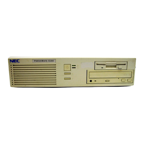
Page 18: Front Features
Front Features The following figures identify the components, lamps, and controls on the front of the system. Brief descriptions of the components follow the figures. PowerMate 5100 Series System Front View A – System Controls and Lamps B – CD-ROM Drive (not installed in all systems) C –... -
Page 19: Back Features
Suspend button — suspends system operation for saving power in systems with Windows 95 or Windows 98 installed. An amber power lamp lights when in suspend (power-saving) mode. Pressing any key or moving the mouse resumes system operation. The Suspend button does not function in systems with Windows NT 4.0 installed. -
Page 20: Audio Connectors
Audio Connectors A – Microphone In Jack B – Line Out Jack External connectors allow the attachment of peripheral devices such as a monitor, keyboard, mouse, and printer. The system has the following external connectors. LAN connector — The RJ-45 local area network (LAN) connector permits connection of the system to an Ethernet LAN for communication with other computers. -
Page 21: Inside Features
VGA monitor connector — Attach a video graphics array ® (VGA)-compatible monitor (NEC MultiSync monitor or other VGA-compatible monitor) with a 15-pin connector to this AGP board connector. Expansion board slots — Use these slots to install one or two optional boards (graphics, fax/modem, or network). -
Page 22: Security Features
NEC Security The NEC Security utility allows password protection and permits the user to disable access to the diskette drive, COM ports, or printers. Refer to Section 2, “System Configuration,” for information on using the NEC Security utility. -
Page 23: Components
Windows Network Security Features The Windows Network Security feature is available through the Windows operating system. Check the Windows documentation for details. Chassis Intrusion Notification Whenever the chassis cover is removed, LANDesk Client Manager logs the incident and reports it on screen the next time the system is booted. See Section 2, “System Configuration,”... -
Page 24: Riser Board
For further information on the system board, see Section 4, “System Board.” Section 6, “Illustrated Parts Breakdown” lists the NEC CSD part number for the system board. Riser Board... -
Page 25: Hard Drive
Connector locations for the IDE hard drive connectors on the riser board are given in Section 5, “Riser Board.” Section 6, “Illustrated Parts Breakdown” lists the NEC CSD part numbers for the hard drives. Hard drive specifications are given in Section 10, “Specifications.”... -
Page 26: Pci Graphics Board
The drive is connected as the master device on the secondary channel. CD-ROM jumper settings are included in Section 2, “System Configuration.” Section 6, “Illustrated Parts Breakdown” lists the NEC CSD part number for the CD-ROM drive. Specifications for the CD-ROM drive are given in Section 10, “System Specifications.”... -
Page 27: Fax/Modem Board
Fax/Modem Board Some systems come with a fax/modem board (U.S. Robotics Python V90) preinstalled. The board operates as a fax system and data modem according to the operating system and software installed. The modem board offers a full- duplex speakerphone and 56,600 bits per second (bps) data/14,400 bps fax communications. -
Page 28: System Configuration
System Configuration Interrupt Requests Jumper Settings BIOS Setup Video Modes Utilities... -
Page 29: Interrupt Requests
BIOS Update utility LANDesk Client manager NEC Auto Backup utility NEC Select Install CD NEC Driver CD Cheyenne Backup NEC Security NEC SNMP Agent NEC WebTelligent NEC Configuration Change Notice. -
Page 30: Parallel Port Interrupts
Interrupt Level Assignments* Interrupt Priority Interrupt Device I/O Channel Check IRQ00 System Timer IRQ01 Keyboard IRQ02 Programmable Interrupt Cascade IRQ03 COM2* IRQ04 COM1* IRQ05 LPT2 (plug and play option)/Audio integrated on system board/User available IRQ06 Diskette Drive Controller IRQ07 Parallel Port 1 IRQ08 Real-Time clock IRQ09... -
Page 31: Serial Port Interrupts
Serial Port Interrupts The interrupts for serial port 1 and serial port 2 are given in the following table. Any interrupts used for the built-in serial ports are not available for ISA parallel ports. Also, if serial ports share an interrupt, verify that hardware and software added to the system can share these interrupts without problems. -
Page 32: System Board Jumper Settings
Enables BIOS recovery procedures. The BIOS attempts to Mode recover the BIOS configuration. A Recovery diskette is required (downloadable from the NEC CSD website. Riser Board LAN Jumper Settings The factory settings for LAN jumper block JP4 on the riser board are shown in the following table. -
Page 33: Hard Drive Jumper Settings
Hard Drive Jumper Settings Hard drive jumpering varies according to the particular model in the system and how that model is configured. The following hard drive models are available for your system from NEC CSD: Seagate Maui 2.1-GB Fujitsu Pico Bird 4.3-GB Quantum Fireball 6.4-GB... -
Page 34: Fujitsu Pico Bird 4.3-Gb Ide Hard Drive Jumper Settings
Fujitsu Pico Bird 4.3-GB IDE Hard Drive Jumper Settings The factory settings for the jumpers on the Fujitsu Pico Bird 4.3-GB IDE hard drive are shown in the following table. The settings are for a single drive installed in the system. Specifications for the hard drives are included in Section 10. -
Page 35: Quantum Fireball 8.4-Gb Ide Hard Drive Jumper Settings
Factory setting: pins PK-1 and PK-2 open. NEC 32X CD-ROM Drive Jumper Settings The factory settings for the jumpers on the NEC 32X CD-ROM drive are shown in the following table. The drive is set as the master device on the secondary channel. -
Page 36: Lucky Goldstar 32X Cd-Rom Drive Jumper Settings
Lucky Goldstar 32X CD-ROM Drive Jumper Settings The factory settings for the jumpers on the Lucky Goldstar 32X CD-ROM drive are shown in the following table. The drive is set as the master device on the secondary channel. The CD-ROM cable plugs onto the Secondary IDE connector on the riser board. -
Page 37: 56-Kbps Fax/Modem Board Jumper Settings
56-Kbps Fax/Modem Board Jumper Settings The factory settings for the jumpers on the fax/modem board are as follows. For Windows 95 and Windows 98 systems, the jumper blocks for COM port and IRQ settings are not jumpered (factory default) or are parked on pin 1 of a pair. For Windows NT systems, the jumpers settings are shown in the following table. -
Page 38: How To Start Bios Setup
configure system connections for peripherals such as diskette drive, hard drives, and devices connected to the printer port and serial ports customize the system with security features such as passwords, diskette drive restriction, virus check reminder, and system backup reminder set system parameters after the CMOS battery is replaced. -
Page 39: How To Use Setup
BIOS Setup Main Menu How to Use Setup Use the keys shown on the bottom of the Main Menu to make selections or to exit the current menu. The following table describes the navigation keys. Navigation Keys Function Provides help for the parameter field being displayed. Exits the menu Enter Executes Command or Selects submenu... -
Page 40: Main Menu
Main Menu Choose the Main menu by selecting Main in the legend bar on the Main menu screen. Other Main menu options are available by selecting submenus. Use the arrow keys to select one of the Main menu options and press Enter select a submenu. -
Page 41: Reset Configuration Data
Reset Configuration Data Select Yes to clear the PCI/PnP configuration data stored in FLASH ROM on the next system reboot. A Yes setting reverts to the No setting after reboot. The default setting is Numlock This field controls whether the Num Lock key on the keyboard is On or Off at bootup. -
Page 42: Peripheral Configuration Parameters
Peripheral Configuration Parameters Menu Item Settings and Description 3F8, 2F8 (default), 3E8, 2E8 Base I/O Address An asterisk (‘*’) displayed next to an address indicates a conflict with another device. This option only appears if Serial Port B is Enabled. IRQ3 (default), IRQ4 Interrupt An asterisk (‘*’) displayed next to an interrupt indicates a... -
Page 43: Ide Configuration
IDE Configuration This menu configures IDE devices as they are added, removed, or changed. Use the fields in the following table to configure the system when making any IDE device changes. IDE Device Configuration Parameters Menu Item Settings and Description IDE Controller Disabled, Primary, Secondary, Both This field enables the primary, secondary, or both interface... -
Page 44: Floppy Options
IDE Device Configuration Parameters Menu Item Settings and Description Maximum Capacity Displays capacity in MB. When Type is set to Auto, the value in the Maximum Capacity field is computed from the auto-detected values in Cylinders, Heads, and Sectors, and the field is read only. Multi-Sector Transfers Disabled , 2 sectors, 4 sectors, 8 sectors, 16 sectors... -
Page 45: Dmi Event Logging
DMI Event Logging This menu keeps track of system events. Use the fields in the following table to configure DMI events. Bring up the submenu by pressing Enter DMI Event Logging Menu Item Settings and Descriptions Event Log Capacity This field is read-only and cannot be changed from the BIOS Setup utility. -
Page 46: Video Configuration
Video Configuration This menu is used to set video palette snooping and AGP Aperture size fields. Use the fields in the following table to set the video configuration. Bring up the submenu by pressing Enter Video Configuration Menu Item Settings and Descriptions Disabled, Enabled Palette Snooping Set palette snooping (also called RAMDAC shadowing) to... -
Page 47: Keyboard Configuration
Resource Configuration Menu Item Settings and Descriptions C800 – CBFF Available, Reserved CC00 – CFFF D000 - D3FF An Available setting indicates that the specified block of upper D400 - D7FF memory is available on the system. A Reserved setting D800 –... -
Page 48: Power Menu
Security Menu Options Menu Item Settings and Descriptions Set User Password [Enter] Use this field to set or change the user password. Press Enter to bring up the dialog box where the password can be entered and confirmed. Do not create a user password that is a subset of the supervisor password. -
Page 49: Boot Menu
Power Menu Options Menu Item Settings and Descriptions Power Management Settings: Disabled, Enabled (default). When set to Enabled, all other Power Management options can be configured. Fan Always On No, Yes Select Yes to force the fan to remain on when the system is in a powered-managed state. - Page 50 Boot Menu Options Menu Item Settings and Descriptions On LAN Power On, Stay Off This option enables the system to be contacted via a LAN even when your system is in a power reduction state. On LAN does not work if the After Power Failure option is set to Stay Off.
-
Page 51: Exit Menu
Exit Menu Selecting the Exit menu displays the exit options listed in the following table. Exit Menu Options Menu Item Settings and Description Exit Saving Changes Saves the setting just made and exits BIOS. Exit Discarding Changes Discards the changes just made and reverts back to the settings existing before starting the BIOS session. -
Page 52: Video Modes
Video Modes Some systems come with an XPERT@Work PCI graphics board preinstalled in the system. This board comes with either 4 MB or 8 MB of synchronous graphics random access memory (SGRAM). To take full advantage of the computer’s installed video board and extended graphics modes listed below, use the video driver that comes preinstalled on the system. -
Page 53: Bios Update Utility
Update the BIOS with a BIOS flash diskette containing the latest version of the BIOS code. The diskette can be obtained from NEC Computer Systems Division or the latest BIOS can be downloaded from the NEC CSD Bulletin Board Service (BBS) onto a diskette. The BIOS can also be downloaded from the NEC CSD website. -
Page 54: Landesk Client Manager
(local machine) or enable/disable the serial ports, printer, or diskette drive (system administrator) back up and restore system configuration files back up system and application software using the NEC Auto Backup utility troubleshoot receive notice of system events (for example, if the system is running low... -
Page 55: Inventory
For managing workstations, Client Manager sets up a connection to all the workstations running on the network to allow the administrator to monitor the functions of each workstation. The monitoring is in real time so that if an unhealthy workstation is fixed, the screen can be refreshed to view the new correct PC health. -
Page 56: Dmi
It can also be used to “set” attribute values in real time. Monitoring Capabilities An NEC MagicEye™ Technology chip on the system board supports many new and advanced real-time monitoring capabilities used by DMI. The chip provides the following:... -
Page 57: Using The Chassis Intrusion Notification Feature
4. Exit from LANDesk Client Manager. NEC Auto Backup On systems that use the Windows 95 operating system, NEC Auto Backup is a data management and backup program that operates in conjunction with LANDesk Client Manager’s DMI and the Self-Monitoring Analysis and Reporting Technology (S.M.A.R.T.) Hard Drive instrumentation. -
Page 58: Nec Select Install Cd
Cheyenne Backup. NEC Select Install CD The system comes with an NEC Select Install compact disc (CD). The CD contains all the system software files that came with the computer, including the operating system, device drivers, applications, the NEC Help Center online user’s guide, and the Healthy Environment file. -
Page 59: Choosing A Restore Program
CD after rebuilding the hard drive, or at any time to reinstall a software package that came with the computer. See “Installing Applications” in this section and Appendix A, “NEC PowerMate 5100 Series Release Notes,” for details on installing applications. -
Page 60: Rebuilding The Hard Drive And Restoring The Operating System
Windows 98 system while leaving applications and data files intact, see “Restoring the Operating System.” The following sections explain how to use the NEC Select Install CD to rebuild and restore the system. See “Auto Rebuild and Restore” to repartition and reformat the hard drive with the OS restore. -
Page 61: Welcome Screen
Welcome Screen 2. Click to continue (or to exit the program). Continue Exit A License Agreement screen appears with three options: Back, Reject, and Accept. button returns to the Welcome screen. Back button terminates the restoration process. Reject button signals acceptance of the terms of the license and Accept allows the program to continue. - Page 62 4. Click to do a basic operating system restore. Auto After clicking in Windows 95 or Windows 98, the Partition Auto Information screen appears. (In Windows NT 4.0, the FAT16 Partition warning screen appears as described later in this procedure.) 5.
-
Page 63: Custom Rebuild And Restore
To reinstall any of the applications or device drivers that came with the computer, follow the procedures in “Installing Applications” and in Appendix A, “NEC PowerMate 5100 Series Release Notes.” To install drivers that didn’t come with the computer follow the procedures in “NEC Driver CD.”... - Page 64 A License Agreement screen appears with three options: Back, Reject, and Accept. Back button returns to the Welcome screen. button terminates the restoration process. Reject button signals acceptance of the terms of the license and Accept allows the program to continue. 3.
- Page 65 The Format Mode screen appears with four options: Back, Quick, Full, and Exit. Click Back to return to the Partition Information screen. Click to do a quick hard drive format. Quick Click to do a full hard drive format. Full Click Exit to terminate the restore process.
-
Page 66: Restoring The Operating System
To install device drivers that did not come with the computer, follow the procedures in “NEC Driver CD.” Restore the applications or drivers that were not provided by NEC by using the vendor diskettes(s) or CD-ROM(s) included in its original packaging. -
Page 67: Welcome Screen
After the system boots from the CD, the Operating System Restore Welcome screen appears (see the following figure). Welcome Screen 2. Click Continue to continue (or Exit to exit the program). A License Agreement screen appears with three options: Back, Reject, and Accept. - Page 68 Close 11. Proceed through the Printer Wizard dialog boxes to install a printer or click Cancel This completes the OS Restore (or “Fix OS”) procedure. Proceed to the next section (see “Installing Applications” or “NEC Driver CD”). System Configuration 2-41...
-
Page 69: Installing Applications
1. With the operating system running, insert the Select Install CD in the CD-ROM drive tray. The CD autorun feature generates the NEC Selective Application Restore Program screen (see the following figure). If you do not have autorun enabled, open Windows Explorer, click on the CD-ROM icon, and double-click Setup.exe. -
Page 70: Using The Selective Application Restore Program On A Remote Cd
If the computer is connected to a network and set up to access a shared CD-ROM drive, a System Administrator can install the applications associated with the OS from the NEC Select Install CD in the remote CD-ROM drive. System Configuration 2-43... - Page 71 Click . The driver installs and the system reboots. 2. Insert the NEC Selective Install CD into the shared CD-ROM drive. 3. Do a map connection to the shared CD-ROM drive. From the system with the shared CD-ROM drive, double click Computer and right click on the CD-ROM drive.
-
Page 72: Nec Help Center Online Documentation
NEC Help Center Online Documentation NEC CSD has included an online NEC Help Center on the NEC Select Install CD. Use the Selective Application Restore program to provide access to all the information provided with the computer. -
Page 73: Installing The Nec Help Center Online Documentation
NEC Driver CD to install the drivers required for system operation. Read this section in its entirety before using the NEC Driver CD to install any optional drivers on the system. -
Page 74: Installing Drivers With The Nec Driver Cd
Doing so can damage the operating system. 1. Install the device requiring the new driver before installing the driver. 2. With the operating system running, insert the NEC Driver CD into the CD-ROM drive. The CD autorun feature launches the NEC Driver CD window. - Page 75 Click . The driver installs and the system reboots. 3. Insert the NEC Driver CD into the shared CD-ROM drive. 4. Do a map connection to the shared CD-ROM drive. From the system with the shared CD-ROM drive, double click Computer and right click on the CD-ROM drive.
-
Page 76: Cheyenne Backup
NEC Security On systems that run the Windows 95 or Windows 98 operating system, NEC Security features allow a local user to change NEC Security passwords and enable a system administrator to control local machine devices, including printer ports, serial ports, and diskette drives. -
Page 77: Installing The Nec Snmp Agent
Installing the NEC SNMP Agent The NEC SNMP Agent software is on the NEC Select Install CD. Install the software on a Windows 95, Windows 98, or Windows NT configured system as follows. (The NEC SNMP Agent software can also be downloaded from the NEC CSD website at www.nec-computers.com... - Page 78 (for example, 157.123.176.100) must be entered in the Traps for “Public Community” to receive traps from the NEC SNMP agents. For the NEC SNMP Agent to send a trap to the NEC SNMP Desktop Manager, the port number can be configured from the registry: "HKEY_LOCAL_MACHINE\SOFTWARE\Packard Bell...
-
Page 79: Configuring The Nec Snmp Agent For Windows 98
(for example, 157.123.176.100) must be entered in the Traps for “Public Community” to receive traps from the NEC SNMP agents. For the NEC SNMP Agent to send a trap to the NEC SNMP Desktop Manager, the port number can be configured from the registry: "HKEY_LOCAL_MACHINE\SOFTWARE\Packard Bell... -
Page 80: Configuring The Nec Snmp Agent For Windows Nt
(for example, 157.123.176.100) must be entered in the Traps for “Public Community” to receive traps from the NEC SNMP agents. For the NEC SNMP Agent to send a trap to the NEC SNMP Desktop Manager, the port number can be configured from the registry: "HKEY_LOCAL_MACHINE\SOFTWARE\Packard Bell... -
Page 81: Nec Webtelligent
Management Interface (DMI) version 2.0, and the world wide web to perform administrative tasks across multiple platforms, either locally or remotely over a network. Through NEC WebTelligent, the managed client desktop PC administrator can manage from a desktop computer using the Netscape or Microsoft Internet Explorer web browser. -
Page 82: Nec Webtelligent Requirements
Reduced Costs WebTelligent is free with the purchase of an NEC PowerMate Managed desktop computer WebTelligent is available as a free download from the NEC CSD website (www.nec-computers.com). NEC WebTelligent Requirements WebTelligent installs on a Windows 95, Windows 98, or Windows NT web... -
Page 83: Nec Webtelligent Installation
TCP/IP. NEC WebTelligent Installation The NEC WebTelligent software and the NEC Auto Discovery Agent software are on the NEC Select Install CD. Install the software onto a Windows 95, Windows 98, or Windows NT web server as follows. ! CAUTION Before installing NEC WebTelligent from the NEC Select Install CD, refer to Appendix A, “NEC PowerMate 5100... - Page 84 Administration to start the browser. 3. Install the WebTelligent software on the web server using the NEC Select Install CD. ! CAUTION Before installing NEC WebTelligent from the NEC Select Install CD, refer to Appendix A, “NEC PowerMate 5100 Series Release Notes,”...
-
Page 85: Nec Webtelligent Login Screen
Look for the directory C:\Program files\PBNEC\WebTelligent Discovery Agent. If it is not there, install the software from the NEC Select Install CD or download it from the NEC CSD website (www.nec-computers.com). -
Page 86: Nec Configuration Change Notification
NEC Configuration Change Notification NEC Configuration Change Notification is an application that runs as Windows starts. It works with the LANDesk application and DMI (Desktop Management Interface) software to determine if there has been a change in the processor, main memory, or hard drive since the last startup. -
Page 87: Disassembly And Reassembly
Disassembly and Reassembly System Unit Cover Removal Expansion Board Removal Front Panel Removal Blank Panel and Metal Slot Cover Removal DIMM Module Removal Processor Subsystem Removal 5 1/4-Inch Device Removal 3 1/2-Inch Hard Drive Removal 3 1/2-Inch Diskette Drive Removal Power Supply Removal System Board Removal Riser Board Removal... -
Page 88: Powermate 5100 Series Disassembly Sequence
This section contains step-by-step disassembly procedures for the system unit. A simplified disassembly illustration is provided with most procedures. Section 6 includes a parts list and an illustrated parts breakdown showing an exploded view of the system. A Phillips-head screwdriver is the only required tool. For complete disassembly of the system unit, follow the disassembly order listed in the following table. -
Page 89: System Unit Cover Removal
! CAUTION Before handling boards or chips, ground yourself to release static. System Unit Cover Removal The following subsections describe how to remove and replace the system unit cover. ® Note: For systems with LANDesk Client Manager, a chassis intrusion is reported to the Client Manager whenever the cover is removed. -
Page 90: Loosening The Cover Screw
Loosening the Cover Screw A – Thumb Screw 4. Slide the cover back about one-half inch; if necessary, anchor one hand on the rear of the system unit as you slide the cover. 5. Lift up at the top of the cover to release the cover tabs from the chassis slots. Releasing the Cover A –... -
Page 91: Replacing The System Unit Cover
Replacing the System Unit Cover Replace the system unit cover as follows. Note: To prevent damage to system cables, carefully tuck the cables out of the path of the cover. 1. Position the cover over the system unit. The front edge of the cover should be about one-half inch behind the front edge of the chassis. -
Page 92: Expansion Board Removal
Expansion Board Removal Remove any installed expansion board(s) as follows. 1. Remove the system unit cover (see “Removing the Cover”). 2. Label and remove any cables connected to the board. 3. Remove the screw that secures the board to the support bracket. Set the screw aside (it will be used to secure the slot cover once the board is removed). -
Page 93: Front Panel Tab And Slot Locations
2. Press in on the left and right locking tabs and press down on the middle tab (see the following figure). Note: The inside of the front panel has three locking tabs, two on the left and right sides and one in the middle. The panel also has two pop-in tabs on each side and four slots on the bottom. -
Page 94: Blank Panel And Metal Slot Cover Removal
Blank Panel and Metal Slot Cover Removal Remove the blank panel from the front panel and the metal slot cover from the chassis as follows. 1. Remove the front panel as previously described. 2. Remove the blank panel from the storage slot by pressing the blank panel tabs and pushing the blank panel out (see the following figure). -
Page 95: Dimm Module Removal
DIMM Module Removal Remove a DIMM module from the system board as follows. 1. Turn off the system and disconnect the system power cord. 2. Remove the system unit cover and floor (see “Removing the System Unit Cover”). 3. Locate the DIMM sockets on the system board. 4. -
Page 96: 1/4-Inch Device Removal
Removing the Processor Subsystem A – Locking Tabs (one not shown) B – Processor/Heatsink Assembly C – Retention Mechanism D – Processor Slot E – System Board 5 1/4-Inch Device Removal Remove a 5 1/4-inch device from the system unit as follows. 1. -
Page 97: 1/2-Inch Hard Drive Removal
Removing a 5 1/4-Inch Device 3 1/2-Inch Hard Drive Removal Remove the 3 1/2-inch hard drive as follows. 1. Remove the system unit cover as previously described. 2. Unplug the power and signal cables from the hard drive. Note: When reinstalling the drive, note that all power cables are keyed to fit only in the correct position. -
Page 98: 1/2-Inch Diskette Drive Removal
Removing the Hard Drive Screws A – Bracket Screws B – Internal Hard Drive Screws C – Internal Hard Drive D – Bracket Slots 3 1/2-Inch Diskette Drive Removal Remove the 3 1/2-inch diskette drive as follows. 1. Remove the system unit cover as previously described. 2. -
Page 99: Power Supply Removal
Diskette Drive Removal A – Diskette Drive Screw (hidden) B – Diskette Drive Screws (hidden) C – Diskette Drive Power Supply Removal Remove the power supply as follows. WARNING Before removing the system unit cover, turn off the power and unplug the system power cable. Power is removed only when the power cable is unplugged. -
Page 100: System Board Removal And Replacement
Removing the Power Supply Screws A – Power Supply Screws System Board Removal and Replacement Remove and replace the system board as follows. System Board Removal Remove the system board as follows. 1. Ensure that all external cables are disconnected from the rear of the system. 2. -
Page 101: System Board Replacement
Removing the System Board 4. If the system board is being replaced, remove the CPU and the DIMMs from the board and install them on the new board. System Board Replacement If you remove the system board from the computer, take care in replacing the board. -
Page 102: Replacing The System Board
Replacing the System Board 3. Slide the system board partway into the system unit along the chassis rail guide. Stop sliding the board when the outside edge of the system board aligns with the outside edge of the chassis (see the following figure). ! CAUTION To prevent damage to the latch, align the system board with the outside edge of the chassis before closing the latch. -
Page 103: Correct Alignment Of The System Board
Correct Alignment of the System Board A – Rail B – Latch Open C – Edge of Chassis D – Edge of System Board 4. Push the latch closed. This slides the board the rest of the way into the system unit and secures it into the riser board connector. -
Page 104: Riser Board Removal
Secured Position of Latch A – Rail B – Latch Closed C – Edge of Chassis D – Edge of System Board 6. Replace the system unit cover (see “Replacing the Cover”). Riser Board Removal Remove the riser board as follows. 1. -
Page 105: Cmos Battery Removal
5. Slide the riser board to the right to remove the RJ-45 connector from the LAN slot in the rear of the chassis. 6. Lift the riser board out of the system unit. CMOS Battery Removal Remove the 3-volt lithium battery from the system board as follows. 1. -
Page 106: Removing The Battery
3. Using a small, flat-blade screwdriver, carefully slip the blade under the spring-loaded tab and gently pry up until the battery pops out of the socket. ! CAUTION Pry up gently on the spring-loaded tab as shown in the following figure. The battery should pop completely out of the socket so that you can remove and discard it properly. - Page 107 8. Connect external peripherals and power cables. 9. Run the Setup Utility to reconfigure the system parameters (see Section 2, “System Configuration”). Disassembly and Reassembly 3-21...
-
Page 108: System Board
System Board Connectors, Jumpers, and Sockets Components Pin Assignments Resources... -
Page 109: Connectors, Jumpers, And Sockets
This section describes the locations of connectors, jumpers, and sockets on the system board, including external cable connectors, internal board connectors, jumper locations, and upgrade sockets. Included in this section are procedures for setting jumpers on the system board and a DIMM memory upgrade path for the DIMM sockets. Also included are descriptions of system board components, component pin assignments, system memory map, and I/O addresses. -
Page 110: Internal Connectors
Internal Connectors Locations of the internal connectors on the system board are shown in the following figure. Following the figure is a table that lists the connectors and the page where their pin assignments are defined. System Board Internal Connector Locations A –... -
Page 111: System Board Jumpers
System Board Jumpers The system board contains a single, three-pin configuration jumper block (J6C1). The jumper block is used with the BIOS Setup Maintenance menu for reconfiguring processor speed when upgrading the system processor. It is also used for resetting the password and for BIOS recovery. The following figure shows the location of jumper block J6C1 on the system board. -
Page 112: Changing Processor Speed
Jumpers are set correctly at the factory for the system configuration. Only change (or check) the appropriate jumper setting if upgrading the processor. NEC CSD recommends using needle-nose pliers to move a jumper. Access the BIOS Setup utility and record any customized settings. See “BIOS Setup”... - Page 113 WARNING System power must be off before changing a jumper setting. 2. Remove the system unit cover (see “Removing the System Unit Cover” in Section 3). 3. Locate jumper block J6C1 on the system board. 4. Use needle nose pliers to move the jumper from pins 1 and 2 (Normal mode) to pins 2 and 3 (Configure mode).
-
Page 114: Clearing A Password
Only change (or check) the appropriate jumper setting if you forgot your password or want to change the password. NEC CSD recommends using needle-nose pliers to move a jumper. Access the BIOS Setup utility and record any customized settings. See “BIOS Setup”... -
Page 115: Bios Recovery
BIOS update was interrupted. To perform a BIOS Recovery, use the following procedure in conjunction with a BIOS Recovery program. The program can be downloaded from the NEC CSD BBS, ftp site, or website. The BIOS Recovery program must be downloaded to a diskette, not to the hard drive. -
Page 116: Upgrade Sockets
11. Replace the system unit cover. Connect system power cables and external options. 12. Power on the system and press to open the BIOS Setup utility before POST. Set the BIOS settings (see Section 2). Upgrade Sockets The system board has the following sockets: processor socket DIMM sockets. -
Page 117: Checking System Memory
See the following tables for supported DIMMs and for sample DIMM upgrade paths. To determine the memory needed for a memory upgrade, see “Checking System Memory.” To remove or install a DIMM, see Section 3, “Disassembly and Reassembly.” Pin assignments for the DIMM sockets are included at the end of this section. -
Page 118: Components
2-Mb Flash ROM for fast economical BIOS upgrades PCI local bus for fast data transfer National Heceta LM79 chip for monitoring voltage, temperature, and security (NEC MagicEye™ technology) integrated sound (Crystal audio system) power management with power saving mode, featuring inactivity timer... -
Page 119: System Board Components
(sleep/resume, remote wake on LAN, and support for ACPI); real-time clock with 256-byte, battery-backed CMOS static RAM (SRAM); 16-bit counters based on 82C54. National Heceta LM80 Provides voltage, temperature, and security monitoring (NEC MagicEye technology). 4-12 System Board... -
Page 120: Processor And Secondary Cache
32-bit DRAM on the system board, instead of from the slower 8-bit flash device. NEC’s Flash ROM allows fast, economical BIOS upgrades. The Flash ROM is a reprogrammable EPROM containing both the system and video BIOS. Using... -
Page 121: System Memory
the expense of replacing ROM BIOS chips is eliminated, so system maintenance costs are reduced there is less chance of inadvertently damaging the system board than when physically replacing ROMs new technology can be incorporated while maintaining corporate standards network administrators can exercise company-wide control of BIOS revisions. -
Page 122: Plug And Play
Plug and Play The system comes with a Plug and Play BIOS in support of Plug and Play technology. Plug and Play simplifies setup procedures for installing Plug and Play expansion boards. With Plug and Play, adding a Plug and Play expansion board is done by turning off the system, installing the board, and turning on the system. -
Page 123: Pci/Ide Ports
PCI/IDE Ports The system board supports two high-performance PCI/IDE ports: a primary port and a secondary port (the port connectors are located on the riser board which plugs into the system board). Each port supports up to two devices for a total of four IDE devices. -
Page 124: Serial Interface
Parallel interface signals are output through the system board’s 25-pin, D-subconnector. The connector is located at the back of the system unit. Pin assignments for the parallel interface connector are included at the end of this section. Serial Interface The system has two 16C550 UART compatible serial ports (COM1 and COM2) integrated on the I/O controller. -
Page 125: Graphics Capabilities
The system also supports PCI graphics boards. A PCI graphics board installs in one of the computer’s PCI expansion slots. NEC CSD offers the ATI XPERT@Work 4-MB AGP PCI graphics board as a Build-to-Order option. This board contains 4 MB of SGRAM. -
Page 126: Integrated Audio
ATI XPERT@Work PCI Graphics Board Resolutions, Refresh Rates, Scan, and Clock Speeds Screen Maximum Refresh Horizontal Scan (KHz) Pixel Clock (MHz) Resolution Rate (Hz) 640 x 480 100.2 800 x 600 125.9 1024 x 768 120.6 1152 x 864 108.6 1280 x 1024 106.4 1600 x 1200... -
Page 127: Parallel Interface Connector
Parallel Interface Connector The following table lists the pin assignments for the parallel interface connector on the system board. Parallel Interface Pin Assignments Signal Name Signal Name Strobe Auto Feed Data Bit 0 Fault Data Bit 1 INIT Data Bit 2 SLCT IN Data Bit 3 Ground... -
Page 128: Keyboard And Mouse Connectors
Keyboard and Mouse Connectors The keyboard and mouse are PS/2-style connectors and can be plugged into either connector on the system board. The system unit detects their presence at power on. Pin assignments are given in the following table. Keyboard and Mouse Pin Assignments Signal Name Data No connection... -
Page 129: Vga Interface Connector
VGA Interface Connector Video signals are output from the AGP subsystem or PCI video board through a VGA interface connector, which is a 15-pin, D-subconnector (VESA VS890803-2) located at the rear of the system unit or in one of the PCI expansion slots. -
Page 130: Line Out Connector
Line Out Connector The pin assignments for the line out connector (J8P1) are provided in the following table. Line Out Connector Pin Assignments Signal Ground Line Out Left Line Out Right DIMM Sockets The following table lists the pin assignments for system board DIMM sockets. DIMM Socket Pin Assignments Signal Signal... - Page 131 DIMM Socket Pin Assignments Signal Signal Signal DQ48 DQm0 DQ49 DQM1 DQ50 DQ32 DQ51 DQ33 DQ34 DQ52 DQ35 NC (VREF) DQ36 DQ37 DQ38 DQ53 DQ39 DQ54 NC (BA1) DQ40 DQ55 DQ41 DQ56 DQ42 DQ57 DQ43 DQ58 DQ44 DQ59 DQ45 DQM2 DQ60 DQM3 DQ46...
-
Page 132: Resources
DIMM Socket Pin Assignments Signal Signal Signal DQ16 DQ17 DQM4 Resources The system memory map, I/O addresses, and DMA settings are given in the following sections. System interrupt settings, parallel interrupt settings, and serial interrupt settings are included in Section 2, “System Configuration.” Memory Map The system memory map is shown in the following table. -
Page 133: I/O Address Map
I/O Address Map Address (Hex) I/O Device Name 0000-000F PIIX4 - DMA controller 1 (channel 0-3) 0020-0021 PIIX4 - interrupt controller 1 002E-002F Super I/O controller configuration registers 0040-0043 PIIX4 - counter/timer 1 0048-004B PIIX4 - counter/timer 2 0060 Keyboard controller byte - reset IRQ 0061 PIIX4 - NMI, speaker control 0064... - Page 134 I/O Address Map Address (Hex) I/O Device Name 0378-037F Parallel port 1 0388-038D AdLIB (FM synthesizer) 03B4-03B5 Video (VGA) 03BA Video (VGA) 03BC-03BF Parallel port 3 03C0-03CA Video (VGA) 03CC Video (VGA) 03CE-03CF Video (VGA) 03D4-03D5 Video (VGA) 03DA Video (VGA) 03E8-03EF COM3 03F0-03F5...
-
Page 135: Dma Settings
DMA Settings The system’s DMA settings are given in the following table. DMA Settings DMA Setting Device Audio Audio/parallel port Diskette drive Parallel port (for ECP or EPP)/audio Reserved —– cascade channel Available Available Available * In Plug and Play systems, these settings are typical but may vary by configuration. 4-28 System Board... -
Page 136: Riser Board
Riser Board Subsystem Cable Connectors IDE and Diskette Drive Cable Connectors PCI and ISA Cable Connectors Power Supply Connectors Jumper Settings... - Page 137 This section shows the following riser board connector locations, connector pin assignments, jumper locations, and jumper settings: subsystem cable connectors CD audio in connector modem in connector Wake-On LAN connector Wake on LAN technology enables remote wakeup of the computer through a network.
-
Page 138: Subsystem Connectors
Subsystem Connectors The subsystem cable connector locations on the riser board are shown in the following figure. Pin assignments are given in the tables following the figure. Riser Board Cable Connector Locations A – CD Audio In (JP1) B – Modem-In (JP2) C –... -
Page 139: Wake-On Lan Connector
Wake-On LAN Connector The pin assignments for Wake-On LAN connector J7 are as follows. Wake-On LAN Connector J7 Pin Assignments Signal Name 5VSB Modem Wake LAN Wake Chassis Intrusion Detection Connector The pin assignments for chassis intrusion detection connector J5 are as follows. Chassis Intrusion Detection Connector J5 Pin Assignments Signal Name Intrusion -... -
Page 140: Fan Connector
Front Panel Connector (F.P.) Pin Assignments Signal Name IR TX IR SELO IR MODE SEL IR SEL1 Fan Connector The pin assignments for fan connector J3 are as follows. Fan Connector J3 Pin Assignments Signal Name +12V (fused) Ground +12V (fused) Riser Board 5-5... -
Page 141: Lan Connector
LAN Connector The pin assignments for LAN connector RJ-45 are as follows. LAN Connector RJ-45 Pin Assignments Signal Name TX - TX - RX - No Connect No Connect RX - No Connect No Connect NLX Connector P1 (PCI Segment) The following table lists connector pin assignments for the PCI segment of riser board NLX connector P1. - Page 142 NLX Connector P1 Pin Assignments (PCI Segment) Signal Type Termination GNT0# PCICLK4 GNT1# 3.3VDC REQ2# REQ3# AD[30] AD[25] REQ1# AD[27] 3.3VDC AD[23] AD[20] AD[18] AD[17] IRDY# DECSEL# 3.3VDC STOP# PERR# SERR# C/BE[1]# AD[13] AD[10] C/BE[0]# AD[00] AD[06] 3.3VDC Riser Board 5-7...
- Page 143 NLX Connector P1 Pin Assignments (PCI Segment) Signal Type Termination AD[05] AD[01] AD[03] AD[02] 5VDC PCSPKR_RT AUDIO +12V PCSPKR_L AUDIO +12V PCICKL0 PCICLK1 SER_IRQ MISC PCIINT2# 3.3VDC PCICLK3 GNT3# 3.3VDC GNT2# AD[31] REQ0# AD[29] AD[28] AD[26] 3.3VDC AD[24] C/BE[3]# AD[22] AD[21] 5-8 Riser Board...
- Page 144 NLX Connector P1 Pin Assignments (PCI Segment) Signal Type Termination AD[19] AD[16] 3.3VDC C/BE[2]# FRAME# TRDY# SDONE LOCK# SBO# 3.3VDC AD[15] AD[14] AD[11] AD[12] AD[09] 3.3VDC AD[08] AD[07] AD[04] PCI_PM# Riser Board 5-9...
-
Page 145: Nlx Connector P1 (Isa Segment)
NLX Connector P1 (ISA Segment) The following table lists connector pin assignments for the ISA segment of riser board NLX connector P1. NLX Connector P1 Pin Assignments (ISA Segment) Signal Type Termination RSTDRV IOCHK# SD[6] SD[7] SD[4] 5VDC SD[2] SD[5] SD[0] SMEMW# SA[19]... - Page 146 NLX Connector P1 Pin Assignments (ISA Segment) Signal Type Termination IOCS16# MEMCS16# IRQ11 IRQ10 IRQ15 IRQ12 IRQ14 DRQ0 MEMR# MEMW# SD[9] DRQ5 DRQ6 5VDC SD[12] DACK7# A100 SD[14] A101 MASTER# 5VDC IRQ9 DRQ2 SD[3] OWS# SD[1] IOCHRDY SA[18] SMEMR# SA[16] IOR# Riser Board 5-11...
- Page 147 NLX Connector P1 Pin Assignments (ISA Segment) Signal Type Termination DRQ3 SA[15] SA[13] 5VDC REFRESH# SA[11] SA[10] IRQ7 IRQ6 SA[8] SA[6] DACK2# SA[4] SA[3] SA[2] SA[1] SA[0] SBHE# LA[23] LA[22] LA[21] LA[20] LA[19] LA[18] LA[17] DACK0# DACK5# SD[8] DACK6# SD[10] 5VDC 5-12 Riser Board...
-
Page 148: Nlx Connector P1 (Ide, Diskette Drive, And Front Panel Segment)
NLX Connector P1 Pin Assignments (ISA Segment) Signal Type Termination SD[11] DRQ7 SD[13] B100 SD[15] B101 NLX Connector P1 (IDE, Diskette Drive, and Front Panel Segment) The following table lists connector pin assignments for the IDE, diskette drive, and front panel segment of the riser board NLX connector P1. NLX Connector P1 Pin Assignments (IDE, Diskette Drive, and Front Panel Segment) Signal... - Page 149 NLX Connector P1 Pin Assignments (IDE, Diskette Drive, and Front Panel Segment) Signal Type Termination A122 IDEB_DD9 A123 IDEB_DD6 A124 IDEB_DD5 A125 IDEB_DD11 A126 IDEB_DD12 A127 A128 IDEB_DD2 A129 IDEB_DD15 A130 IDEB_DIOW# A131 IDEB_DMARQ A132 IDEB_IORDY A133 A134 IDEB_DMACK# A135 RESERVED A136 IDEB_DA0...
- Page 150 NLX Connector P1 Pin Assignments (IDE, Diskette Drive, and Front Panel Segment) Signal Type Termination A154 FAN_TACH3 MISC A155 FAN_CTL MISC A156 5VDC A157 USB1/3_N MISC A158 USB1/3_P MISC A159 USB1/3_OC# MISC A160 USB2/4_N MISC A161 USB2/4_P MISC A162 USB2/4_OC# MISC A163 A164...
- Page 151 NLX Connector P1 Pin Assignments (IDE, Diskette Drive, and Front Panel Segment) Signal Type Termination B117 IDEA_DA1 B118 IDEA_DA0 B119 IDEA_CS1# B120 IDEB_DD8 B121 IDEB_DD7 B122 B123 IDEB_DD10 B124 5VDC B125 IDEB_DD4 B126 IDEB_DD3 B127 IDEB_DD13 B128 IDEB_DD14 B129 IDEB_DD1 B130 IDEB_DD0 B131...
- Page 152 NLX Connector P1 Pin Assignments (IDE, Diskette Drive, and Front Panel Segment) Signal Type Termination B149 DSKCHG# FLOPPY B150 B151 IRSL0 MISC B152 IRSL1 MISC B153 IRSL2 MISC B154 IRTX MISC B155 IRRX MISC B156 FP_SLEEP MISC B157 FP_RST# MISC B158 B159 PWRLED#...
-
Page 153: Nlx Connector Jp3 (Supplemental Connector Segment)
NLX Connector JP3 (Supplemental Connector Segment) The following table lists connector pin assignments for the supplemental connector segment of riser board NLX connector JP3. NLX Connector JP3 Pin Assignments (Supplemental Connector Segment) Signal Type Termination CD_IN_LT AUDIO Analog 1V RMS AGND MIC_IN AUDIO... -
Page 154: Ide And Diskette Drive Cable Connectors
IDE and Diskette Drive Cable Connectors The IDE and diskette cable connectors are shown in the following figure. Pin assignments are given in the tables following the figure. IDE and Diskette Drive Cable Connectors A – Diskette Drive Connector B – Primary IDE Connector C –... -
Page 155: Diskette Drive Connector
IDE Interface Pin Assignments Signal Name Signal Assignment Addr 1 No Connection Addr 0 Addr 2 Chip Select 0- Chip Select 3P (3S) Activity- Ground Diskette Drive Connector The pin assignments for the diskette drive connector are given in the following table. -
Page 156: Pci And Isa Cable Connectors
Card Placement The riser board expansion slots can accept up to two expansion boards in combinations listed in the following table for boards available from NEC CSD. These boards include the U.S. Robotics Python 56K V90 modem, the 4-MB XPERT@Work PCI video board, and/or an Intel Pro 100M2 Kaiser network board (LAN). -
Page 157: Pci Bus Pin Assignments
PCI Bus Pin Assignments Signal Signal Signal Signal -12V AD16 AD17 +12V No Connect 3.3V CBE2- No Connect FRAME- No Connect No Connect IRDY- TRDY- 3.3V PCIINT3- DEVSEL- PCIINT1- PCIINT2- STOP- PCIINT4- 3.3V PLOCK- Reserved No Connect SDONE PERR- Reserved SBO- 3.3V Reserved... -
Page 158: Isa Bus Connector
ISA Bus Connector The pin assignments for the ISA bus connector are given in the following table. ISA Bus Connector Pin Assignments Signal Signal IOCHK- DACK2- RSTDRV BALE IRQ9 DRQ2 -12V 0WS- MEMCS16- SBHE- +12V IOCS16- LA23 IOCHRDY IRQ10 LA22 SMEMW- IRQ11 LA21... -
Page 159: Power Supply Cable Connectors
Power Supply Cable Connectors The power supply cable connector locations on the back of the riser board are shown in the following figure. Pin assignments are given in the tables following the figure. Riser Board Power Supply Cable Connector Locations A –... -
Page 160: Jumper Settings
Jumper Settings The riser board contains two 3-pin jumper blocks: LAN JP4 and fan JP5. The following figure shows the locations of the jumpers on the two jumper blocks. The jumper settings are given in the tables following the figure. Riser Board Jumper Locations A –... -
Page 161: Changing Jumpers
Changing Jumpers Use the following steps to change the jumper settings on either jumper block. 1. Power off and unplug the system and any external options. WARNING System power must be off before changing a jumper setting. 2. Remove the system unit cover (see “Removing the Cover” in Section 2) and install the optional LAN board or the three-wire fan. -
Page 162: Illustrated Parts Breakdown
Illustrated Parts Breakdown Parts and Options Field Replaceable Unit (FRU) List Illustrated Parts Breakdown (IPB) -
Page 163: Parts And Options
This section contains the illustrated parts breakdown (IPB) and NEC CSD part numbers for the PowerMate 5100 Series Build-to-Order (BTO) systems. The following tables list telephone numbers for ordering system parts and options field-replaceable parts for the system documentation and packaging for the system. -
Page 164: Powermate 5100 Series System Fru List
Speakers, 9-Watt, Altec, Mist White 160323 Power Supply (145 Watt) NLX, Astec 213-00024 Riser Card, NLX with Onboard LAN 203-00027 NEC 32X Max CD-ROM Drive (CDR1900A/PBM) 730330 Diskette Drive, 3.5-inch, 1.44-MB, Bezel, mist white 219-00012 2.1-GB Hard Drive, Seagate, EIDE, Maui 300814 4.3-GB Hard Drive, Fujitsu, EIDE... -
Page 165: Illustrated Parts Breakdown (Ipb)
819-181926-000 Driver CD 370-00346 NEC Select Install CD-ROM – Windows 95 370-00344 NEC Select Install CD-ROM – Windows 98 (when available) 370-00342 NEC Select Install CD-ROM – Windows NT 4.0 370-00343 Illustrated Parts Breakdown (IPB) The following figure shows the illustrated parts breakdown (IPB) for PowerMate 5100 Series computers. -
Page 166: Powermate 5100 Series Computer Illustrated Parts Breakdown
PowerMate 5100 Series Computer Illustrated Parts Breakdown* * This data was August July 1998. For an up-to-date listing of spare parts, call FaxFlash at 1-888-329-0088 (or 1-978-635-6090 outside the U.S.) and order document 42181926. Illustrated Parts Breakdown 6-5... -
Page 167: Preventive Maintenance
Preventive Maintenance System Cleaning Keyboard Cleaning Mouse Cleaning... -
Page 168: System Cleaning
This section contains general information for cleaning and checking the system, keyboard, and monitor. The system unit, keyboard, and monitor require cleaning and checking at least once a year, and more often if operating in a dusty environment. No other scheduled maintenance is required. -
Page 169: Mouse Cleaning
Removing the Keyboard Enclosure A – Screw (1 of 10) 2. Separate the two halves of the enclosure. 3. Clean the enclosure and keys with a damp cloth. A small, soft-bristle brush may be used to clean between the keys. Do not wet or dampen the keyboard’s printed circuit board. - Page 170 4. Turn the mouse over and remove the ball. 5. Clean the mouse as follows: Clean the mouse ball with tap water and a mild detergent, then dry it with a lint-free cloth. Remove any dust and lint from the mouse socket. 6.
-
Page 171: Troubleshooting
Troubleshooting Checklist Diagnostics... -
Page 172: Checklist
This section provides information to help isolate and repair system malfunctions at the field level. The system has a built-in program that automatically checks its components when the system is powered on. If there is a problem, the system displays an error message. If this happens, follow any instructions on the screen. If screen messages do not help or an error message does not appear, refer to the information in this section to help determine and correct the problem. -
Page 173: Diskette Drive Problems
System emits continuous beeps. Turn the system off, wait at least five seconds, and turn the system on. If the beeps continue, call the NEC CSD Technical Support Center. System does not maintain date, time, system configuration information. Change the battery (see “Battery Replacement” in Section 3, “Disassembly and Reassembly”). -
Page 174: Monitor Problems
If the diskette drive busy lamp does not light when loading the diskette, try a different diskette. If this loads, the problem is in the software. Non-System Disk or Disk Error message displayed. If trying to boot from the diskette drive, insert a diskette with system files into drive A. -
Page 175: Cd-Rom Drive Problems
Image appears on screen but nothing happens when using the mouse or keyboard. Make sure the keyboard or mouse cable is firmly connected to the rear of the system. If this does not help, turn off the system, wait five or more seconds, and turn on the system. -
Page 176: Diagnostics
Speaker volume is too low. Adjust the volume control on the speaker. If the volume is still too low, adjust the volume through the system software. See the Windows Multimedia online help. Sound is only coming from one speaker. Balance the speaker output by adjusting the balance in the sound software. - Page 177 Problems and Solutions Problem Symptom Solution Operating system Intermittent beeping at power-on. 1. Check system configuration (see does not boot Computer beeps more than once Section 2). and is unable to complete boot-up. 2. Check all jumper settings and verify that drives are enabled (see Section 2).
- Page 178 Problems and Solutions Problem Symptom Solution Cannot access hard drive. 1. Check signal/power connections between hard disk, PCB, power supply. 2. Check hard drive jumper settings. 3. Check power supply. 4. Check hard drive cable and hard drive. Replace as necessary. 5.
- Page 179 Problems and Solutions Problem Symptom Solution Monitor malfunction Blank display. 1. Press any key or move the mouse to (cont’d) ensure power management has not blanked the display. 2. Check that the monitor power ON/OFF switch is ON. 3. Check that the monitor cable is attached to the video connector at the back of the system.
- Page 180 Problems and Solutions Problem Symptom Solution CD-ROM drive Cannot access CD-ROM drive. 1. Check that the CD-ROM driver software malfunction (cont’d) is loaded and not corrupted. 2. Check signal and power connections between the CD-ROM drive, riser board, and power supply. 3.
-
Page 181: Nec Csd Information Services
NEC CSD Information Services Service Telephone Numbers Technical Support Product Information FaxFlash Service... -
Page 182: Service Telephone Numbers
FaxFlash service. Service Telephone Numbers The following table lists the telephone numbers for the NEC CSD service and support functions. NEC CSD Service and Support Telephone Numbers Service Telephone Numbers To contact NEC CSD Technical Support Center (TSC): In the U.S. -
Page 183: Technical Support
Technical Support The following sections provide information for obtaining technical support from NEC CSD. With access to a telephone, modem, and/or fax machine, you can use these services to obtain information on a 24-hour basis. NEC CSD Website If you have a modem or a network board and an Internet Service account, you can access the NEC CSD website. -
Page 184: Technical Support Services
Center. (NEC CSD technical support is for U.S. and Canadian customers only; international customers should check with their sales provider.) Direct assistance is available 24 hours a day, 7 days a week. Call the NEC CSD Technical Support Center, toll free, at 1 (800) 632-4525 (U.S. -
Page 185: Nec Csd Bulletin Board Service
NEC CSD Bulletin Board Service If you have access to a modem, you can use the NEC CSD Bulletin Board Service (BBS) to get the latest information on hardware and software. The BBS allows you to download files (video drivers, printer drivers, BIOS updates, etc.) to a diskette for system enhancements and upgrades. -
Page 186: Faxflash Service
14. Press Enter FaxFlash Service The NEC CSD FaxFlash service is a self-help, automated electronic information service for obtaining up-to-date product application notes, installation procedures, troubleshooting tips, data sheets, technical information bulletins, illustrated parts lists, part numbers, and other information about your system. - Page 187 Catalog 6, NEC Ready Consumer Desktop Systems Catalog 7, NEC PowerMate Commercial Desktop Systems ® Catalog 8, NEC Portable Systems (including Versa Notebook and ™ MobilePro Handheld computers). Catalogs 5, 6, 7, and 8 contain technical support information, including Technical Information Bulletins, Illustrated Parts lists, Frequently Asked Questions (FAQs) lists, and other product support documents.
-
Page 188: Specifications
Specifications System Board Riser Board Keyboard Mouse Speaker System Unit Diskette Drive Hard Drives Power Supply Fax/Modem Board Graphics Board CD-ROM Drives Environmental and Safety... -
Page 189: System Specifications
This section contains the specifications for the various components comprising the PowerMate 5100 Series systems. The following table lists the specifications and the pages where the specifications can be found. System Specifications Specification Go to Page System board 10-3 Riser board 10-4 Keyboard 10-4... -
Page 190: System Board Specifications
System Board Specifications The specifications for the system board are included in the following table. System Board Specifications Feature Specification System Board Intel KU440EX with 82440EX AGPset and integrated audio Processor Celeron 266 MHz MMX or 300 MHz MMX; Pentium II 233 MHz, 266 MHz MMX, 300 MHz MMX, 333 MHz MMX, Cache Memory 32 KB of primary cache (16-KB data, 16-KB instruction) -
Page 191: Riser Board Specifications
Riser Board Specifications The specifications for the riser board are included in the following table. Riser Board Specifications Feature Specification Features NLX compatible Support for a total of four IDE devices; 40-pin connectors 2 PCI connectors 1 ISA connector System board slot (170-pin edge connector) Industry Standard Interfaces Two PCI/IDE connectors (primary and secondary) Diskette drive connector... -
Page 192: Mouse Specifications
Mouse Specifications The specifications for the mouse are included in the following table. Mouse Specifications Feature Specification Mouse Microsoft IntelliMouse Features 2-button with cursor movement wheel X & Y encoder resolution: 400 PPI opto-mechanical Wheel Resolution: zoom resolution 18 counts per revolution Operating Characteristics Vin = 115 V or 230 V as appropriate Ta = 25 Thermal stabilization - 1 hour minimum... -
Page 193: System Unit Specifications
System Unit Specifications The specifications for the system unit are included in the following table. System Unit Specifications Feature Specification Dimensions Width: 15.5 inches (39.37 cm) Depth: 14.5 inches (36.83 cm) Height: 3.6 inches (9.07 cm) Device Slots One 5 1/4-inch front accessible slot One 3 1/2-inch front accessible slot One 3 1/2-inch internal slot Expansion Board Slots... -
Page 194: Diskette Drive Specifications
Diskette Drive Specifications The specifications for the diskette drive are included in the following table. Diskette Drive Specifications Feature Specification Diskette Drive NEC Diskette Drive FD1231H Recording Capacity High density mode: Unformatted: 2.00/1.00 MB Formatted: 1440 KB (512B 18 Sec) -
Page 195: 2.1-Gb Seagate Hard Drive Specifications
2.1-GB Seagate Hard Drive Specifications The specifications for the 2.1-GB Seagate hard drive are included in the following table. 2.1-GB Seagate Hard Drive Specifications Feature Specification Capacity and Interface 3.2-GB Quantum Fireball ST Formatted Gbytes 2.1GB/Ultra ATA (512 bytes/sector)/ Interface Performance Zones per surface: 15 Tracks per surface: 7,066... -
Page 196: 4.3-Gb Fujitsu Hard Drive Specifications
2.1-GB Seagate Hard Drive Specifications Feature Specification Operating Shock @ 11 msec (Gs) Nonoperating Shock @ 2 msec (Gs) Operating Temperature (°C) 5 to 55 Nonoperating Temperature (°C) -40 to 60 Average Acoustics, Idle(bels-sound power) Average Acoustics, Idle(dBA-sound pressure) Physical Dimensions Height (in/mm) 1/25.4 Width (in/mm) -
Page 197: 6.4-Gb Quantum Hard Drive Specifications
4.3-GB Fujitsu Hard Drive Specifications Feature Specification Power +5V +/-5%; 100 mV peak-to-peak maximum allowable ripple/noise 12V +/-10%; 200 mV peak-to-peak allowable ripple/noise Temperature (non-condensing) Operating: 5 to 55 C (41 to 136.5 F) Non-operating: -40 to 60 C (-40 to 149 F) Humidity (non-condensing) Operating: 5% to 85% rh, 30 C (86 F) Non-operating: 5% to 95% rh, 40 C (104 F) -
Page 198: 8.4-Gb Quantum Fireball Se Hard Drive Specifications
6.4-GB Quantum Fireball ST Hard Drive Specifications Feature Specification Track-to-track: 2.0 ms typical Average write: 11.0 ms typical; 13.0 ms max. Full stroke: 20.0 ms typical; 24.0 ms max. Data transfer rate Disk to read buffer: 78 Mb/sec. min.; 132 Mb/sec. max Read buffer to IDE bus (PIO Mode with IORDY): 16.7 MB/sec. -
Page 199: Nlx145-Watt Power Supply Specifications
8.4-GB Quantum Fireball SE Hard Drive Specifications Feature Specification Average: 9.5 ms read, 11 ms write Maximum: 12.0 ms read, 13 ms write Data transfer rate Buffer to disc: 158 Mb/sec. Buffer to host: 33 MB/sec. max. Interleave: 1:1 Buffer Size 128 KB Power +5V +/-5%;... -
Page 200: Fax/Modem Board Specifications
Fax/Modem Board Specifications The specifications for the fax/modem board are included in the following table. Fax/Modem Board Specifications Feature Specification Fax/Modem Board U.S. Robotics Python V.90 (56.6 Kbps Data (maximum speed) x2 technology ITU-T V.34+ ITU-T V.34 ITU-T V.32bis ITU-T V.32 ITU-T V.23 ITU-T V.22bis ITU-T V.22... -
Page 201: Lucky Goldstar 32X Cd-Rom Drive Specifications
Lucky Goldstar 32X CD-ROM Drive Specifications The specifications for the Lucky Goldstar 32X CD-ROM drive are included in the following table. Lucky Goldstar 32X CD-ROM Drive Specifications Feature Specification 32X CD-ROM Drive LG Electronics CD-ROM drive CRD-8240B Applicable Disc Format Mixed Mode (Audio and Data Combined) CD-DA, Mode 1 (basic format), Mode 2 form 1 and form 2 Photo-CD (Multisession), CD-SA Ready... -
Page 202: Nec 32X Cd-Rom Drive Specifications
NEC 32X CD-ROM Drive Specifications The specifications for the NEC 32X CD-ROM drive are included in the following table. NEC 32X CD-ROM Drive Specifications Feature Specification 32X CD-ROM Drive NEC CDR-1900A/PBM Data Transfer Rate Blocks/second 12X - 32X 900 - 2460... -
Page 203: Sound Board Specifications
Sound Board Specifications The specifications for the sound board are included in the following table. Sound Board Specifications Feature Specification Sound Board Model Creative Labs CT4335 AWE-32 Digitized Sound Sound Blaster compatible 8-bit/16-bit DMA transfer; 8-bit ADPCM decompression in hardware; advanced 16-bit software-based real time audio compression/decompression Input: microphone, stereo line-in, CD-Audio, FM music, or multiple source recording... -
Page 204: Environmental And Safety Specifications
Environmental and Safety Specifications The system environmental and safety specifications are included in the following table. Environmental and Safety Specifications Feature Specification Recommended Operating Temperature: 50 F to 95 F (10 C to 35 C) Environment Relative Humidity: 20% to 80% Administrative Compliance UL 1950 - safety CSA C22.2 No. -
Page 205: Release Notes
Release Notes General Notes Windows 95 Issues Windows NT Issues... -
Page 206: General Notes
1. Install Microsoft Internet Explorer first and alone, before installing any other application on the NEC Select Install CD. 2. Install and set up LANDesk Client Manager alone and before installing NEC Security, Cheyenne Backup utility, NEC Configuration Change Notification, the NEC Auto Backup utility, or NEC WebTelligent. - Page 207 3. Read the following information to ensure that you properly set up your system configuration. Do not install both the NEC SNMP Agent and LANDesk Client Manager on the same computer. The two applications are incompatible, and neither can be removed using the uninstall utility. To remove them, a full restore must be performed after which all applications must be reinstalled.
-
Page 208: Uninstalling The Nec Snmp Agent Or Landesk Client Manager
If you attempt to remove one of the applications, a full operating system restore will have to be performed using the NEC Select Install CD. After the full restore, all appropriate applications should be reinstalled from the CD using the Selective Application Restore program or a setup.exe program. -
Page 209: Correcting Video Corruption
Change the background wallpaper from any of the following: NEC3D, Metal Links, Forrest, Stitches, or Clouds. Right click anywhere on the desktop and click Properties Click the tab in the Display Properties window. Background Highlight a different wallpaper pattern. Click NEC PowerMate 5100 Series Release Notes A-5... -
Page 210: Correcting Video Corruption In A Windows Nt System
3. Highlight a different wallpaper pattern. Click Configuring the System for the NEC SNMP Agent TCP/IP must be enabled before the NEC SNMP Agent can be used. See “Changing Network Settings” below for instructions on enabling TCP/IP. (The NEC SNMP Agent is installed from the NEC Select Install CD. See the document Installing Your Applications and Online Documentation for instructions on installing the SNMP Agent.) -
Page 211: Windows 95 Issues
Start and select Shutdown. When this occurs, the message for properly turning off the computer (“It is safe to shut down your system”) never appears. This is a known Microsoft issue. NEC PowerMate 5100 Series Release Notes A-7... -
Page 212: Using Ldcm Administrator With Ipx Network Protocol
This is a known Intel LDCM issue. For security and compatibility reasons, Intel recommends using Windows NT for LDCM Administrator functions. NEC CSD recommends the use of TCP/IP protocol. However, if IPX must be used, follow these instructions: 1. Run REGEDIT (press... -
Page 213: Clicking The Product Catalog Button
Microsoft Windows NT 4.0 operating system.. Rebooting the System After Installing Internet Explorer 4.0 After Internet Explorer 4.0 has been installed from the NEC Select Install CD, do not remove the CD until the reboot sequence has begun (anytime following the screen clear, but before the system begins to boot from the CD).. -
Page 214: Glossary
Glossary access time The time period between the supply of an access signal and the output or acceptance of the data by the addressed system. Examples are the access times for DRAMs, SRAMs, hard drives, and CD-ROM drives. Hard drive access time is the time it takes for a computer to get data from the drive. - Page 215 Application Programming Interface. An API is a series of functions that programs can use to make the operating system do routine or repetitive tasks. Using Windows APIs, for example, a program can open windows, files, and message boxes (as well as perform more complicated tasks) by passing a single instruction.
- Page 216 audio Relating to or capable of producing sound. Multimedia computers make extensive use of audio. A digital movie format created by Microsoft. AVI is short for “audio/video interleave,” a method of including a digital movie and its accompanying sound in the same file.
- Page 217 Binary digit. The smallest unit of computer data. A single digital piece of information, generally represented by the numeral 0 or 1. Usually the transition between the states of +5V and -5V within a computer, the charge of a transistor in an integrated circuit, or the change in polarity of a magnetic region on a disk.
- Page 218 boot sector The part of the boot block that contains the operating system loader, a program that starts by itself and loads the operating system. Bits per second. The number of bits of data that can be transmitted in one second. Because data compression schemes enable more than one bit per voltage transition, bps is equivalent to baud only if no compression is used.
- Page 219 chassis The metal frame to which the electronic components of the computer (such as the system board, power supply, and drive bays) are attached The chassis goes inside the system unit cover. checksum A number, calculated from a block of data, used to verify the integrity of that data. For example, a modem could send a block of data and include the number of 1’s that occur in the block.
- Page 220 DIMM Dual Inline Memory Module. Circuit board with pins connecting to different memory chips on both sides of the board, which allows for wider and faster data transfer (128-bit). See SIMMs. Direct Memory Access. A method for transferring data, usually between memory and a disk drive, without going through the CPU.
- Page 221 EIDE Extended Integrated Drive Electronics. The EIDE specification is an enhanced version of IDE that allows for faster transfer rates and supports larger hard drive sizes enhanced VGA A video interface that offers more colors or higher resolution than VGA. Enhanced Parallel Port, a parallel port standard for PCs that supports bidirectional communication between the PC and attached device (such as a printer).
- Page 222 hertz (Hz) A unit of frequency equal to one cycle per second. hexadecimal A number system that uses 16 as the base. (Place value indicates powers of 16.) It uses the digits 0-9 and A-F. Used around computers because a byte (eight binary digits) easily converts to a two digit hexadecimal number.
- Page 223 Interrupt Request. A signal that, when received by the CPU, makes it stop what it is going to do something else. An interrupt is a way in which a particular device in a computer communicates with the CPU. PCs have 16 IRQ lines that can be assigned to different devices (for example, printers, scanners, modems).
- Page 224 memory Electronic storage area in a computer that retains information and programs. A computer has two types of memory: read-only memory (ROM) and random access memory (RAM). microprocessor A semiconductor central processing unit that is the principal component of a microcomputer.
- Page 225 overwrite Storing information at a location where information is already stored, thus destroying the original information. page A type of message transmission in which a message is sent or received via modem to a paging device from a computer (with paging communications software) or telephone.
- Page 226 port Any connection by which data can enter or leave a computer or peripheral. You Cables are plug into ports. Provides the means for an interface between the microprocessor and external devices. A cable connector is usually plugged into the port to attach the device to the computer.
- Page 227 Self-Monitoring Analysis and Reporting Technology. A hard drive feature that works in conjunction with system software (for example, LANDesk Client Manager, NEC Auto Backup) for identifying a potential problem on the hard drive and automatically backing up system files to a user-specified device, such as a tape or Zip drive.
- Page 228 system board The main printed circuit board inside the system unit into which other boards and major chip components, such as the system microprocessor, are connected. Tracks per inch. track Any of many concentric circular regions on a disk for storing data. Tracks are divided into sectors.
- Page 229 VRAM Video RAM. VRAM is special-purpose memory used by video adapters. Unlike conventional RAM, VRAM can be accessed by two different devices simultaneously. This enables a video adapter to access the VRAM for screen updates at the same time that the CPU provides new data. VRAM yields better graphics performance but is more expensive than normal RAM.
-
Page 230: Index
CD-ROM drives parallel port, 2-3 cabling, 1-12 ASIC hardware monitor, 4-14 features, 1-12 Audio, 4-19 Lucky Goldstar 32X specifications, 10-14 NEC 32X specifications, 10-15 Changing password, 4-7 Battery Chassis intrusion removal, 3-19 detection cable connector, 5-4 removing, 3-20 notification, 1-9, 2-30... - Page 231 3 1/2-inch diskette drive, 3-12 configuring the system for Microsoft 3 1/2-inch hard drive, 3-11 Internet Explorer, A-6 5 1/4-inch device, 3-10 configuring the system for NEC SNMP blank panel, 3-8 Agent, A-6 CMOS battery, 3-19 configuring the system for NEC...
- Page 232 9-4 technical support services, 9-4 Keyboard, 1-11 telephone numbers, 9-2 cleaning, 7-2 website, 9-3 configuration, 2-20 NEC CSD service and support information, specifications, 10-4 NEC driver CD, 2-46 NEC Help Center, 2-46 installing, 2-46 cable connector, 5-6 uninstalling, 2-46...
- Page 233 4-5 socket, 4-9 Online documentation subsystem removal, 3-9 Healthy Environment, 2-46 Product information, 9-4 NEC Help Center, 2-46 Quantum IDE hard drive Parallel interface, 4-16 6.4-GB hard drive specifications, 10-10 Parallel port 8.4-GB hard drive specifications, 10-11 addresses, 2-3, 4-16...
- Page 234 10-4 keyboard, 1-11 Lucky Goldstar 32X CD-ROM, 10-14 local area network, 1-13 mouse, 10-5 mouse, 1-11 NEC 32X CD-ROM, 10-15 PCI graphics board, 1-12 power supply, 10-12 power supply, 1-11 riser board, 10-4 riser board, 1-10 sound board, 10-16...
- Page 235 4-9 interface, 4-17 pin assignments, 4-21 Utilities BIOS update, 2-26 Cheyenne Backup, 2-49 LANDesk Client Manager, 2-27 NEC Auto Backup, 2-30 NEC Configuration Change Notification, 2-59 NEC driver CD, 2-46 NEC Security, 2-49 NEC SNMP Agent, 2-49 NEC WebTelligent, 2-54...
- Page 236 (For United States Use Only) Federal Communications Commission Radio Frequency Interference Statement WARNING: Changes or modifications to this unit not expressly approved by the party responsible for compliance could void the user’s authority to operate the equipment. NOTE: This equipment has been tested and found to comply with the limits for a Class B digital device, pursuant to Part 15 of the FCC Rules.
- Page 237 For battery replacement information, see “CMOS Battery Removal” in Section 3 of this manual or call your NEC CSD dealer or the NEC CSD Technical Support Center. WARNING: There is a danger of explosion if the battery is incorrectly replaced. Replace only with the same or equivalent type recommended by the manufacturer.