Table of Contents
Advertisement
Quick Links
Advertisement
Table of Contents

Related Manuals for Dell PowerConnect W-6000


Summary of Contents for Dell PowerConnect W-6000
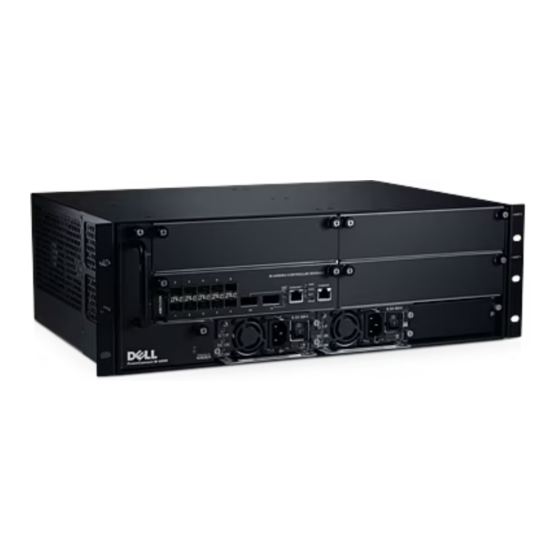
- Page 1 Dell PowerConnect W-6000 controller Installation Guide...
- Page 2 © 2011 Aruba Networks, Inc. AirWave®, Aruba Networks®, Aruba Mobility Management System®, and other registered marks are trademarks of Aruba Networks, Inc. Dell™, the DELL™ logo, and PowerConnect™ are trademarks of Dell Inc. All rights reserved. Specifications in this manual are subject to change without notice.
-
Page 3: Table Of Contents
Features ............................. 23 Rating............................23 Load Sharing ..........................23 Redundancy..........................23 Hot Swap............................ 23 Physical Description ........................24 Power Management ........................25 W-6000M3 Module and PSU Configuration Table .............. 25 Inserting a Power Supply........................ 25 Dell PowerConnect W-6000 Controller | Installation Guide... - Page 4 Physical.............................. 29 Environmental ........................... 29 Operational ............................29 Compliance............................29 Electromagnetic Interference ....................30 United States........................30 Canada ..........................30 Japan..........................30 Europe ..........................30 Safety............................30 Lithium Battery Notice..................... 30 Laser Notice........................31 Dell PowerConnect W-6000 Controller | Installation Guide...
-
Page 5: Preface
Dell support and service information Overview of this Manual This manual is for trained technicians responsible for installing the Dell PowerConnect W-6000 controller. The manual is organized as follows: The Dell PowerConnect W-6000 Controller Chassis Chapters 1, 2, and, 3 describe the W-6000 controller, and provide instructions for mounting the chassis, attaching power, and performing initial power-on tests. -
Page 6: Contacting Support
Enter only one choice. Do not type the braces or bars. Contacting Support Table 2 Dell Contact Information Website Main Website dell.com Support Website support.dell.com Documentation Website support.dell.com/manuals 6 | Preface Dell PowerConnect W-6000 Controller | Installation Guide... -
Page 7: Chapter 1 System Overview
Chapter 1 System Overview The Dell PowerConnect W-6000 controller is an enterprise-class, modular chassis which connects, controls, and intelligently integrates wireless Access Points (APs) and Air Monitors (AMs) into the wired LAN. This chapter introduces you to the W-6000 controller. It describes the general features of the modular system and illustrates key physical elements. - Page 8 CAUTION: Never insert or remove a power supply while its power switch is in the On position or while the power cord is plugged in. First verify the power switch is Off and the cord is unplugged. CAUTION: Be sure to exercise proper Electrostatic Discharge (ESD) precautions when handling the Dell W-6000 controller and its components.
-
Page 9: Chapter 2 Installing The Chassis
Connecting power to the W-6000 controller Pre-Installation Checklist You will need the following during installation: Dell PowerConnect W-6000 Controller Dell PowerConnect W-6000 Controller rack mounting hardware (included) Phillips or cross-head screwdriver 19-inch equipment rack, or equivalent ... -
Page 10: Precautions
Do not disassemble the chassis or any module. They have no internal user-serviceable parts. When service or repair is needed, “Contacting Support” on page 6. Requirements Minimum Configuration A Dell PowerConnect W-6000 Controller must include the following basic components: One W-6000 controller chassis One fan tray ... -
Page 11: Rack Mounting Kit
For proper air circulation, leave at least 10 cm (4 inches) clearance for the vents on the left, right, front, and rear of the chassis. Leave additional space in front of the chassis to access power cords, network cables, and indicator LEDs. Limited electromagnetic interference Dell PowerConnect W-6000 Controller | Installation Guide Installing the Chassis | 11... -
Page 12: Rack Mounting The Chassis
Insert the small end of the cage-nut installation tool through the opening in the rail (from the front), and hook the tool over the top lip of the cage nut. 12 | Installing the Chassis Dell PowerConnect W-6000 Controller | Installation Guide... -
Page 13: Adding W-6000M3 Controller Modules
NOTE: By adding modules, you are increasing the total power load. Depending on the modules installed, you may be required to add power supplies to the chassis and/or increase the capacity of your site’s electrical systems. For details, see “Power Management” on page 25. Dell PowerConnect W-6000 Controller | Installation Guide Installing the Chassis | 13... -
Page 14: Connecting Power
Repeat the above Steps 4, 5, and 6 for each installed power supply. Once power is connected, you can perform the power-on test (see page 15). 14 | Installing the Chassis Dell PowerConnect W-6000 Controller | Installation Guide... -
Page 15: Chapter 3 Verifying The Installation
5. You are now ready to perform the initial setup as described in the Aruba Quick Start Guide (which is included in the Accessory Kit) for the software loaded on your controller. Dell PowerConnect W-6000 Controller | Installation Guide Verifying the Installation | 15... - Page 16 16 | Verifying the Installation Dell PowerConnect W-6000 Controller | Installation Guide...
-
Page 17: Chapter 4 The Fan Tray
The Dell PowerConnect W-6000 controller Fan Tray (HW-FT) provides air circulation for cooling the W- 6000M3 modules in the Dell PowerConnect W-6000 controller chassis and is required for their normal operation. Normal operating temperature for the W-6000 controller chassis is between 0 to 40 ºC (32 to 104 ºF). If this temperature range is exceeded, the W-6000 will provide a warning through the software to alert users of the change. - Page 18 Slot Labels: When the fan tray is installed in the W-6000 controller, these labels name the module slots to the immediate right of the fan tray (see Figure 1 on page Fans (on side): Three independent fans provide redundancy for cooling the W-6000 controller cards. 18 | The Fan Tray Dell PowerConnect W-6000 Controller | Installation Guide...
-
Page 19: Replacing A Fan Tray
Damage due to servicing that is not authorized by Dell is not covered by your warranty. Read and follow the safety instructions that came with the product. - Page 20 Use the screwdriver to push in and tighten both of the fastening screws on the faceplate of the newly installed fan tray. Rotate the screws clockwise until moderate resistance is felt, but do not over-tighten. 20 | The Fan Tray Dell PowerConnect W-6000 Controller | Installation Guide...
-
Page 21: Chapter 5 Dell Powerconnect W-6000M3
Each W-6000M3 controller module is capable of supporting up to 512 campus connected APs with the use of Dell AP upgrade licenses. Contact your Dell sales representative for a complete listing of available software licenses. For information on the installation and operation of the Dell PowerConnect W-6000M3 controller module, see the Dell PowerConnect W-6000M3 Controller Module Installation Guide that is included with each module. - Page 22 22 | Dell PowerConnect W-6000M3 Dell PowerConnect W-6000 Controller | Installation Guide...
-
Page 23: Chapter 6 The W-6000 Power Supply Module
Rating The Dell W-6000 Power Supply (HW-PSU-400) is rated at 400 W total output and is auto-ranging to accept 85 to 264 VAC, at 50 to 60 Hz. Up to three 400 W power supplies can be installed in the W-6000 controller. -
Page 24: Physical Description
Power Input Socket: This power socket accepts power cords with standard IEC320 connectors. For proper safety and performance, the cord must be rated to 10 A and conform to grounded electrical standards in the country where the product is used. 24 | The W-6000 Power Supply Module Dell PowerConnect W-6000 Controller | Installation Guide... -
Page 25: Power Management
Damage due to servicing that is not authorized by Dell is not covered by your warranty. Read and follow the safety instructions that came with the product. - Page 26 Verify that your site’s electrical systems can handle the power load for the W-6000. Each power supply (HW-PSU-400) is rated at 400 W total and is auto-ranging to accept 85 to 264 VAC, at 50 to 60 Hz. 26 | The W-6000 Power Supply Module Dell PowerConnect W-6000 Controller | Installation Guide...
-
Page 27: Removing A Power Supply
Damage due to servicing that is not authorized by Dell is not covered by your warranty. Read and follow the safety instructions that came with the product. - Page 28 28 | The W-6000 Power Supply Module Dell PowerConnect W-6000 Controller | Installation Guide...
-
Page 29: Chapter 7 Specifications
Output: 48 V, 8 A Power Consumption 460W (per power supply), maximum Network Management HTML Web-browser interface Standards IEEE 802.1x, IEEE 802.3 10BASE-T, IEEE 802.3u 100BASE-TX, IEEE 802.3ab 1000BASE-T, IEEE 802.3z 1000BASE-SX Dell PowerConnect W-6000 Controller | Installation Guide Specifications | 29... -
Page 30: Compliance
Cet appareil numérique respecte les limites de bruits radioélectriques applicables aux appareils numériques de Classe A prescrites dans la norme sur le matériel brouilleur: “Appareils Numériques,” NMB-003 édictée par le ministère des Communications. Japan VCCI - Class A 30 | Specifications Dell PowerConnect W-6000 Controller | Installation Guide... -
Page 31: Europe
Dispose of used batteries according to the manufacturer’s instructions. Laser Notice The Dell PowerConnect W-6000M3 Controller Module used with this product uses replaceable laser transceiver modules on some ports. CLASS 1... - Page 32 April 2011 | 0510763-02 Dell PowerConnect W-6000 Controller | Installation Guide...