Table of Contents
Advertisement
Quick Links
Advertisement
Table of Contents

Related Manuals for Asus GX2024B - GigaX Switch


Summary of Contents for Asus GX2024B - GigaX Switch
- Page 1 GigaX2024B Layer 2 Managed Switch User Manual...
- Page 2 ASUS; or (2) the serial number of the product is defaced or missing. ASUS provides this manual “as is” without warranty of any kind, either express or implied, including but not limited to the implied warranties or conditions of merchantability or fitness for a particular purpose.
-
Page 3: Federal Communications Commission Statement
GigaX2024B L2 Managed Switch User Manual Federal Communications Commission Statement This device complies with Part 15 of the FCC Rules. Operation is subject to the following two conditions: • This device may not cause harmful interference, and • This device must accept any interference received including interference that may cause undesired operation. -
Page 4: Asus Contact Information
Support Hotlines: (Components) +49-2102-95990 (Notebook PC) +49-2102-959910 Support Fax: +49-2102-959911 Support Email: www.asuscom.de/de/support (for online support) Web Site: www.asuscom.de ASUS COMPUTER (Middle East and North Africa) Address: P.O. Box 64133, Dubai, U.A.E. General Tel.: +9714-283-1774 General Fax: +9714-283-1775 General Email: www.ASUSarabia.com... -
Page 5: Table Of Contents
GigaX2024B L2 Managed Switch User Manual Table of content Introduction ................1 GigaX2024B features ............... 1 Conventions used in this document ......... 2 1.2.1 Notations ..................2 1.2.2 Typography .................. 2 1.2.3 Symbols ..................2 Getting to know the GigaX2024B ........3 Package contents .............. - Page 6 GigaX2024B L2 Managed Switch User Manual 4.2.2 Commonly used buttons and icons ........... 14 System pages ................ 15 4.3.1 Management ................15 4.3.2 IP setup ..................15 4.3.3 Reboot ..................16 Physical interface ..............17 4.5.1 Spanning tree ................19 4.5.1.1 STP status .................
- Page 7 GigaX2024B L2 Managed Switch User Manual 4.6.3 Trap setting ................37 4.6.4 SNMPv3 VGU table ..............38 4.6.4.1 VACM view ................ 38 4.6.4.2 VACM group ..............39 4.6.4.3 USM user ................40 Filter pages ................41 4.7.1 Filter set ..................41 4.7.2 Filter attach ................
- Page 8 GigaX2024B L2 Managed Switch User Manual 5.3.1.2 Delete user ................ 56 5.3.2 Backup and Restore ..............56 5.3.2.1 Backup start-up configuration file ........56 5.3.2.2 Restore start-up configuration file ........57 5.3.3 System management configuration .......... 57 5.3.3.1 Firmware upgrade ............. 57 5.3.3.2 configure terminal ..............
- Page 9 GigaX2024B L2 Managed Switch User Manual 5.3.5.1 show vlan name string ............62 5.3.5.2 Create a vlan entry ............62 5.3.5.3 interface vlan VLAN-ID ............62 5.3.5.4 ip address ................62 5.3.5.5 ip dhcp client ..............63 5.3.5.6 ip route ................63 5.3.6 Spanning Tree ................
- Page 10 GigaX2024B L2 Managed Switch User Manual 5.3.12 Traffic control ................66 5.3.12.1 storm-control ..............66 5.3.12.2 no storm-control ............... 67 5.3.12.3 show storm-control ............67 5.3.13 Dynamic addresses ..............67 5.3.13.1 clear dynamic mac-address ..........67 5.3.13.2 aging time ................ 67 5.3.13.3 no aging time ..............
- Page 11 GigaX2024B L2 Managed Switch User Manual 5.3.18 SNMP ..................71 5.3.18.1 show rmon statistics ............71 5.3.18.2 show snmp-server community ......... 71 5.3.18.3 snmp-server host ............. 71 5.3.19 Filter ..................71 5.3.19.1 deny any host ..............71 5.3.19.2 filter set ................72 5.3.19.3 filter conditions ..............
- Page 12 GigaX2024B L2 Managed Switch User Manual Subnet masks ................ 77 Troubleshooting ..............79 Diagnosing problems using IP utilities ........79 7.1.1 ping .................... 79 7.1.2 nslookup ..................80 Replacing defective fans ............81 Simple fixes ................83 Glossary ................85...
-
Page 13: Introduction
GigaX2024B L2 Managed Switch User Manual Introduction Congratulations on becoming the owner of the ASUS GigaX2024B Layer 2 managed switch! You may now manage your LAN (local area network) through a friendly and powerful user interface. This user manual tells how to set up the GigaX2024B switch, and how to customize its configuration to get the most out of this product. -
Page 14: Conventions Used In This Document
GigaX2024B L2 Managed Switch User Manual • Enterprise MIB for PSU, fan, and system temperature, voltage • Telnet/SSH remote login • TFTP for firmware update and configuration backup • Cisco Like CLI • Web GUI • LEDs for port link status •... -
Page 15: Getting To Know The Gigax2024B
GigaX2024B L2 Managed Switch User Manual Getting to know the GigaX2024B Package contents The GigaX2024B switch package comes with the following items: • GigaX 2024B L2 managed switch • AC power cord • Null modem cable for console interface (DB9) •... -
Page 16: Front Panel
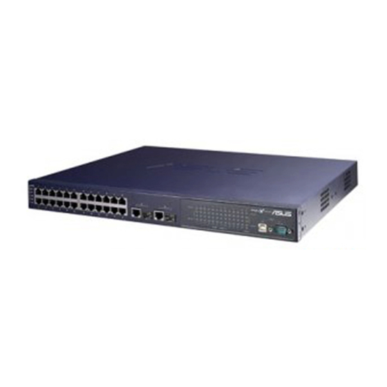
GigaX2024B L2 Managed Switch User Manual Front panel The front panel includes 24 RJ-45 10/100Base-T ports, two 10/100/1000Base-T ports, two SPF GBIC port and LED indicators that show the status of the system, RPS, fan, and ports. Figure 2. Front panel Table 1. -
Page 17: Rear Panel
GigaX2024B L2 Managed Switch User Manual Rear panel The switch rear panel contains the fan modules, a power connector and one RPS port. Figure 3. Rear panel Table 2. Rear panel labels Item Description Power Connector Connects to the supplied power cord FAN1-FAN2 Replaceable system fans Redundant Power Supply connector... -
Page 18: Quick Start Guide
GigaX2024B L2 Managed Switch User Manual Quick start guide This section provides the basic instructions to set up the switch environment. Refer also to the GigaX2024B Installation Guide. Part 1 shows how to install the GigaX2024B on a flat surface or on a rack. Part 2 provides instructions to set up the hardware. -
Page 19: Connect To The Computers Or A Lan
GigaX2024B L2 Managed Switch User Manual 3.2.2 Connect to the computers or a LAN You can use Ethernet cable to connect computers, hubs and other switches to the switch ports. Either crossover or straight-through Ethernet cable can apply for connecting these devices. Use a twisted-pair Category 5 Ethernet cable to connect the 1000BASE-T port. -
Page 20: 3.3 Part 3 - Basic Switch Setting For Management
Set the data format to no parity, 8 data bits and 1 stop bit d) No flow control e) Set VT1000 for emulation mode 4. After setting up the terminal, you can see the prompt “(ASUS)%” on the terminal. - Page 21 IP is 192.168.1.1 and the network mask is 255.255.255.0. Then you should type “ip address 192.168.1.1/24”. e) Type “end”, it will return to previous level with prompt “ASUS#”. f) Type “write”, the changes will be applied and written to configuration file.
-
Page 22: Setting Up Through The Web Interface
GigaX2024B L2 Managed Switch User Manual Figure 5. Console setup 3.3.2 Setting up through the Web interface To connect your PC to the switch, your PC must have a valid IP in your network. Contact your network administrator to obtain a valid IP for the switch. If you wish to change the default IP address of the switch, follow section 3.3.1 to change the IP address. - Page 23 GigaX2024B L2 Managed Switch User Manual Enter your user name and password, and then click OK to enter the configuration Manager. Use the following defaults the first time you log into this interface: Default User Name: admin Default Password: (no password) You can change the password at any time (see section 6.3.1 System Commands.
-
Page 24: Management With The Web Interface
GigaX2024B L2 Managed Switch User Manual Management with the Web Interface The switch provides Web pages that allow switch management through the ® Internet. The program is designed to work best with Microsoft Internet Explorer ® 6.0, or later versions with Java enabled. -
Page 25: Functional Layout
GigaX2024B L2 Managed Switch User Manual Figure 9. Home page Functional layout The web-based configuration page consists of three separate frames. The top frame has a switch logo and front panel as shown in Figures 13 and 14. This frame remains on the top of the browser window all the times and updates the LED status periodically. -
Page 26: Menu Navigation Tips
GigaX2024B L2 Managed Switch User Manual The menu items, as shown in Figure 12, contains all the features available for switch configuration. These features are grouped into categories, e.g. System, Bridge. You can click on any of these to display a specific configuration page. Figure 12. -
Page 27: System
GigaX2024B L2 Managed Switch User Manual System pages System pages include management, IP setup, administration, reboot, and firmware update function. 4.3.1 Management The Management page contains the following information: Model Name: product name MAC Address: switch MAC address System Name: user assigned name to identify the system (editable). System Contact (editable). -
Page 28: Reboot
GigaX2024B L2 Managed Switch User Manual Figure 14. IP Setup 4.3.3 Reboot The Reboot page contains a Reboot button. Clicking the button to reboot the system. Rebooting the system stops the network traffic and terminates the Web interface connection. Warning 4.3.5 Firmware upgrade The Firmware Upgrade and Auto-config page contains the following information:... -
Page 29: Physical Interface
GigaX2024B L2 Managed Switch User Manual Physical interface The Physical Interface shows the realtime Ethernet port status. You can configure the port in following fields: Port: selects the port to configure Admin: enables/disables the port Mode: set sthe speed and duplex mode Flow Control: enables/disables 802.3x flow control mechanism Switchport Mode: sets port to trunk mode or access mode Admin port VLAN: assign the selected port to specific PVID... - Page 30 GigaX2024B L2 Managed Switch User Manual Figure 17. Physical interface - runtime status...
-
Page 31: Spanning Tree
GigaX2024B L2 Managed Switch User Manual Bridge The Bridge page group contains layer 2 configurations, like link aggregation, STP. 4.5.1 Spanning tree The page configures three types of Spanning Tree Protocol. 4.5.1.1 STP status The first page “STP Status” can disable or enable STP. There are three modes STP, RSTP and MSTP can be enabled. -
Page 32: Current Roots
GigaX2024B L2 Managed Switch User Manual 4.5.1.2 Current roots It shows the information of current root bridge which include • Instance ID • The VLAN group belong to which instance ID • MAC Address of root bridge • Priority of root bridge •... -
Page 33: Bridge Parameters
GigaX2024B L2 Managed Switch User Manual 4.5.1.3 Bridge parameters The spanning-tree parameters of BPDU transmission can be configured on this panel: Hello Time: the interval between the generation of configuration BPDU Max Age: a timeout value to be used by all Bridges in the LAN Forward Delay: a timeout value to be used by all bridges in the LAN Bridge Priority: the switch priority in the LAN Transmission Limit: The root switch of the instance always sends a BPDU (or... -
Page 34: Port Parameters
GigaX2024B L2 Managed Switch User Manual 4.5.1.4 Port parameters This page contains a display window to show the current configuration for each port. You can select a port then edit it. Click Modify to change the port setting for spanning-tree. The following fields are available: Instance ID(MSTP Only): a spanning-tree instance, you can configure MSTP on your switch to map multiple VLANs into a single STP instance. -
Page 35: Runtime Status
GigaX2024B L2 Managed Switch User Manual 4.5.1.5 Runtime status This page contains a display window to show the current status for each port. Figure 22. Spanning tree - runtime status 4.5.2 Link aggregation static The page configures the link aggregation static group (port trunking). The switch provides maximum 32 link aggregation groups. - Page 36 GigaX2024B L2 Managed Switch User Manual All the ports in the link aggregation group MUST operate in full duplex mode at the same speed. Note All the ports in the link aggregation group MUST be configured in auto-negotiation mode or full duplex mode. This configuration will make the full duplex link possible.
-
Page 37: Lacp
GigaX2024B L2 Managed Switch User Manual 4.5.3 LACP The page configures the LACP group (port trunking). The switch provides maximum 32 link aggregation groups and up to 8 ports per group. This maximum can be achieved on stacking configuration. For standalone GX3112 or GX3112F, the maximum group is 6 since it supplies 12 ports only.The feature supplies five statistics for verification. -
Page 38: Mirroring
GigaX2024B L2 Managed Switch User Manual 4.5.4 Mirroring Mirroring, together with a network traffic analyzer, helps you monitor network traffics. You can monitor the selected ports for egress or ingress packets. Mirror: Selects the mirror group. Each group consists of 24 Fast Ethernet ports and one gigabit port. -
Page 39: Static Multicast
GigaX2024B L2 Managed Switch User Manual 4.5.5 Static multicast This page can add multicast addresses into the multicast table. The switch can hold up to 256 multicast entries. All the ports in the group will forward the specified multicast packets to other ports in the group. Port: selects the port from selection panel. -
Page 40: Igmp Snooping
GigaX2024B L2 Managed Switch User Manual 4.5.6 IGMP snooping IGMP snooping helps reduce the multicast traffics on the network by allowing the IGMP snooping function to be turned on or off. The first part provides the following settings, Enable IGMP Snooping: Globally enable IGMP snooping in all existing VLAN interfaces. -
Page 41: Traffic Control
GigaX2024B L2 Managed Switch User Manual 4.5.7 Traffic control Traffic control prevents the switch bandwidth from flooding packets including broadcast packets, multicast packets and the unicast packets because of destination address lookup failure. The limit number is a threshold to limit the total number of the checked type packets. -
Page 42: Static Addresses
GigaX2024B L2 Managed Switch User Manual 4.5.9 Static addresses You can add a MAC address into the switch address table. The MAC address added by this way will not age out from the address table. We call it static address. The switch only allows 1024 static addresses. MAC Address: enter the MAC address VLAN ID: enter the VLAN ID that the MAC belongs Port Selection: select the port which the MAC belongs... -
Page 43: Vlan Configuration
GigaX2024B L2 Managed Switch User Manual 4.5.10 VLAN configuration You can set up to 254 VLAN groups and show VLAN group in this page. VLAN1 is a default VLAN, which is created by system. It cannot be removed at all. This feature prevents the switch from malfunctions. -
Page 44: Gvrp
GigaX2024B L2 Managed Switch User Manual 4.5.11 GVRP Generic Attribute Registration Protocol (GARP) VLAN Registration Protocol (GVRP) is an application defined in the IEEE 802.1Q standard that allows for the control of VLANs. GVRP will run only on 802.1Q trunk ports and is used primarily to prune traffic from VLANs that does not need to be passed between trunking switches. -
Page 45: Qos And Cos
GigaX2024B L2 Managed Switch User Manual Figure 33. GARP timer 4.5.12 QoS and CoS 4.5.12.1 802.1p priority Eight egress queues on all switch ports. These queues can either be configured with the Weighted Round Robin (WRR) scheduling algorithm or configured with one queue as a strict priority queue and the other queues for WRR. -
Page 46: Cos Queue Mapping
GigaX2024B L2 Managed Switch User Manual Figure 34. 802.1p Priority 4.5.12.2 CoS queue mapping The switch supports four egress queues for each port with a strict priority scheduler. That is, each CoS value can map into one of the four queues. For strict priority, the queue four has the highest priority to transmit the packets. -
Page 47: Qos Bandwidth
GigaX2024B L2 Managed Switch User Manual 4.5.12.3 QoS bandwidth Some VLAN tag related field settings for each port are included in this page. It includes: Port: Select a port from list window to configure Ingress Bandwidth: Maximum ingress bandwidth for selected port Default CoS: every untagged packet received from this port will be assigned to this CoS value in the VLAN tagged Click on Modify to change the content in the port list window. -
Page 48: Snmp
GigaX2024B L2 Managed Switch User Manual SNMP This group offers the SNMP configuration including Community Table, Host Table, and Trap Setting 4.6.1 Community table You can type different community names and specify whether the community has the privilege to do set action (write access) by checking the box. Click OK to save the configuration permanently or Reload to refresh the page. -
Page 49: Host Table
GigaX2024B L2 Managed Switch User Manual 4.6.2 Host table This page links host IP address to the community name that is entered in Community Table page. Type an IP address and select the community name from the drop-down list. Click OK to save the configuration permanently or Reload to refresh the page. -
Page 50: Snmpv3 Vgu Table
GigaX2024B L2 Managed Switch User Manual 4.6.4 SNMPv3 VGU table Thereʼre two articles presenting the new security features defined by SNMPv3. The User-based Security Model (USM), which provides authentication, encryption, and decryption of SNMPv3 packets. The View-based Access Control Model (VACM), which provides access control. The followings are three related pages. -
Page 51: Vacm Group
GigaX2024B L2 Managed Switch User Manual 4.6.4.2 VACM group VACM Group is used to configure the information of SNMPV3 VACM Group. Group Name: enter the security group name. Read View Name: enter the Read View Name that the Group belongs. The related SNMP messages are Get,GetNext,GetBulk. -
Page 52: Usm User
GigaX2024B L2 Managed Switch User Manual 4.6.4.3 USM user USM User is used to configure the information of SNMPV3 USM User. User Name: User name of a specific security group Group Name: enter the security group name Auth Protocol: enter the Auth Protocol that SNMP User and Security Group belong. -
Page 53: Filter
GigaX2024B L2 Managed Switch User Manual Filter pages The switch can filter certain traffic types according to packet header information from Layer 2 to Layer 4. Each filter set includes a couple of rules. You have to attach the filter set to certain ports to make the filter work. 4.7.1 Filter set The switch defines two modes of rules, one is MAC mode and the other is IP... - Page 54 GigaX2024B L2 Managed Switch User Manual The Filter Rule page provides options for rule modes, one is MAC rule and the other is IP rule. If you did not enter the MAC address in the blank box, it means the rule donʼt care the MAC value. In IP rule setup, you can enter any of the 5 types: source IP, destination IP, protocol, source application port and destination application port.
-
Page 55: Filter Attach
GigaX2024B L2 Managed Switch User Manual 4.7.2 Filter attach A filter set is idle if you did not attach it to any ingress port. Use the Filter Attach page to attach a filter set to ingress ports. Click OK to save the configuration. To make the configuration effective, go to the “Save Configuration”... -
Page 56: Security
GigaX2024B L2 Managed Switch User Manual Security The switch supports the 802.1x port-based security feature. Only authorized hosts are allowed to access the switch port. Traffic will be blocked from unauthenticated host. Authentication can be provided via a RADIUS server or the local database in the switch. - Page 57 GigaX2024B L2 Managed Switch User Manual request from the switch, the switch waits upon this time period before sending another authentication request to the port user. Max Reauthent Attempt: Retry count if the port user failed to respond to authentication requests from the switch. Guest Vlan: Specify a guest VLAN to clients that are not 802.1x-capable.
-
Page 58: Dial-In User
GigaX2024B L2 Managed Switch User Manual 4.8.2 Dial-in user Dial-in User is used to define users in the local database of the switch. User Name: New user name. Password: Password for the new user. Confirm Password: Enter the password again. Vlan ID: Specify the VLAN ID assigned to the 802.1x-authenticated clients. -
Page 59: Radius
GigaX2024B L2 Managed Switch User Manual 4.8.3 RADIUS In order to use external RADIUS server, the following parameters are required to be setup: Authentication Server IP: The IP address of the RADIUS server. Authentication Server Port: The port number for the RADIUS server is listening to. -
Page 60: Port Security
GigaX2024B L2 Managed Switch User Manual 4.8.4 Port security The switch also supports port security feature. It enables a systemʼs administrator to control who can connect to their network. You can use the port security feature to restrict input to an interface by limiting and identifying MAC addressed of the stations allowed to access the port. -
Page 61: Port Status
GigaX2024B L2 Managed Switch User Manual Figure 50. Port security 4.8.4.2 Port status This page shows the current port status, MAC address counts, static MAC address counts, and violation count. Port has five statuses: a) NoOper: This indicates port security on the port is configured to disabled. b) SecureUp: This indicates port security is operational. -
Page 62: Secure Mac Address
GigaX2024B L2 Managed Switch User Manual Figure 51. Port status 4.8.4.3 Secure MAC address Secure MAC Address offers three functions for user management: a) Query: You can select a port by “Port Selection” field. After click “Query” button, it will show all MAC addresses on this port. b) Add: User can select some port by “Port Selection”... -
Page 63: Traffic Chart
GigaX2024B L2 Managed Switch User Manual Traffic chart The Statistics Chart pages provide network flow in different charts. You can specify the period time to refresh the chart. You can monitor the network traffic amount in different graphic chart by these pages. Most MIB-II counters are displayed in these charts. -
Page 64: Error Group Chart
GigaX2024B L2 Managed Switch User Manual 4.9.2 Error group chart Selecting the Port and display Color, then clicking the Draw, the statistics window shows you all the discards or error counts for the specified port. The data is updated periodically. Figure 54. -
Page 65: Cable Diagnosis
GigaX2024B L2 Managed Switch User Manual 4.10 Cable diagnosis To analysis the cabling plant for the common cable problems, such as open circuits, short circuits and impedance mismatches. Figure 56. Cable diagnosis 4.11 Save configuration To save configuration permanently, you have to click Save. The setting also takes effective after a successful save. -
Page 66: Console Interface
POST is executing during the system booting time. It tests system memory, LED and hardware chips on the switchboard. It displays system information as the result of system test and initialization. You can ignore the information until the prompt, “ASUS>:” appears. Figure 58. CLI interface 5.1.1 Boot ROM command mode During the POST process, you can enter a “Boot ROM Command”... -
Page 67: Boot Rom Commands
GigaX2024B L2 Managed Switch User Manual Figure 59. Boot ROM command mode 5.1.2 Boot ROM commands The followings are two types of boot ROM commands, • command: The current settings will be displayed. • command with new setting: The current setting will be replaced by specified new setting. -
Page 68: Login And Logout
first time login, you can enter “admin” as the user name (without password). For security reason, please change the user name and password after login. Once you forget the use name and password, you may contact ASUS support team or restore the default user account in the Boot ROM Command mode –... -
Page 69: Restore Start-Up Configuration File
GigaX2024B L2 Managed Switch User Manual CLI Syntax: copy startup-config tftp: URL Example: ASUS# copy startup-config tftp: 192.168.8.56/gx2024b.cfg 5.3.2.2 Restore start-up configuration file Restore the start-up configuration file “ startup_config” of the switch from TFTP server. CLI Syntax: copy tftp: URL startup-config Example: ASUS# copy tftp: 192.168.1.2/gx2024b.cfg startup-config... -
Page 70: End
GigaX2024B L2 Managed Switch User Manual 5.3.3.5 This command let user end current mode and down to enable mode. CLI Syntax: end Example: ASUS# end 5.3.3.6 exit This command let user exit current mode and down to previous mode. CLI Syntax: exit Example: ASUS# exit 5.3.3.7... -
Page 71: System Location
GigaX2024B L2 Managed Switch User Manual 5.3.3.10 System Location Displays the physical location of the switch. This is an RFC-1213 defined MIB object in System Group, and provides the location information on the managed node. CLI Syntax: snmp-server location DWORD Example: (config)# snmp-server location Loop-Taipei Type in the location description in the location description field to change the location. -
Page 72: Reload Default-Config File
GigaX2024B L2 Managed Switch User Manual 5.3.3.14 reload default-config file Use this command to copy a default-config file to replace the current one. CLI Syntax: reload default-config file Example: ASUS# reload default-config file 5.3.3.15 show running-config To show running-config fule. CLI Syntax: show running-config Example: ASUS# show running-config... -
Page 73: Interface Mode
This example shows how to use the flow control configuration command on the switch to set flow control both on. 5.3.4.4 Show L2 interface Use the show interface command on the switch to show interface status. CLI Syntax: show interfaces IFNAME Example: ASUS# show interface fa1/0/2... -
Page 74: Ip Interface
VLANs or one VLAN (if the VLAN ID or name is specified) on the switch. CLI Syntax: show vlan name string Example: ASUS# show vlan name VLAN1 The vlan1 is for system purpose, for example, for firmware upgrade, management, and so on. -
Page 75: Ip Dhcp Client
Example: (config)# ip route 192.168.20.0 255.255.255.0 192.168.20.1 5.3.6 Spanning Tree 5.3.6.1 show spanning-tree summary To show spanning-tree active. CLI Syntax: show spanning-tree summary Example: ASUS# show spanning-tree summary 5.3.6.2 spanning-tree enable and disable Enable/Disable the spanning tree. CLI Syntax: spanning-tree (enable|disable) Example: ASUS# spanning-tree disable 5.3.7 Link aggregation 5.3.7.1... -
Page 76: Trunk Load Balancing
This command sets the Link Aggregation Control Protocol (LACP) operation add/set for the trunk group ports on the switch. CLI Syntax: lacp aggregation-link group <1-6> (add|set) IFLIST Example: ASUS# lacp aggregation-link group1 add fa1/0/1-3 5.3.8.2 disable lacp aggregation-link trunk This command sets the Link Aggregation Control Protocol (LACP) operation add/set or disable for the trunk group ports on the switch. -
Page 77: Mirror Setting
(config)# mirror session 1 destination fa1/0/5 5.3.9.2 Show mirror To show current mirror features. CLI Syntax: Show mirror session Example: ASUS# show mirror session 5.3.9.3 No mirror This command disable the mirror function. CLI Syntax: no mirror session 1 Example: (config)# no mirror session 1 5.3.9.4... -
Page 78: No Mac-Address-Table Multicast
Use the show mac-address-table multicast user EXEC command to display the Layer 2 multicast entries for all VLANs. Use the command in privileged EXEC mode to display specific multicast entries. CLI Syntax: show mac-address-table multicast Example: ASUS# show mac-address-table multicast 5.3.11 IGMP snooping 5.3.11.1 ip igmp snooping This command sets the IGMP snooping function enabled globally. -
Page 79: No Storm-Control
Use the show storm-control configuration command on the switchto show the limit rate of the portʼs total bandwidth used by broadcast/dlf/multicast. CLI Syntax: show storm-control (broadcast|dlf|multicast) Example: ASUS# show storm-control broadcast 5.3.13 Dynamic addresses 5.3.13.1 clear dynamic mac-address Use the write configuration command on the switch to clear dynamic L2 MAC... -
Page 80: Show Mac-Address-Table Aging-Time
VLANs or one VLAN (if the VLAN ID or name is specified) on the switch. CLI Syntax: show vlan name string Example: ASUS# show vlan name VLAN1 5.3.15.2 vlan vid Use the vlan vid command to create vlan entry on the switch. -
Page 81: Name String
Use the clear gvrp statistics configuration command on the switch to clear all the GVRP statistics information on one or all interfaces. CLI Syntax: clear gvrp statistics [IFNAME] Example: ASUS# clear gvrp statistics fa1/0/2 5.3.16.2 gvrp mode This command sets the GVRP feature globally enable or disable on the switch. -
Page 82: Show Gvrp Configuration
GigaX2024B L2 Managed Switch User Manual 5.3.16.3 show gvrp configuration To show gvrp configuration IFNAME status. CLI Syntax: show gvrp interface IFNAME Example: ASUS# show gvrp interface fa1/0/1 5.3.16.4 show gvrp statistics To show gvrp statistics IFNAME status. CLI Syntax: show gvrp statistics [IFNAME] Example: ASUS# show gvrp statistics fa1/0/1 5.3.17... -
Page 83: Qos Ingress Bandwidth
SNMP 5.3.18.1 show rmon statistics To show rmon statistics IFNAME status. CLI Syntax: show rmon statistics [IFNAME] Example: ASUS# show rmon statistics fa1/0/1 5.3.18.2 show snmp-server community To show snmp-server community. CLI Syntax: show snmp-server community Example: ASUS# show snmp-server community 5.3.18.3... -
Page 84: Filter Set
GigaX2024B L2 Managed Switch User Manual 5.3.19.2 filter set This command define an extended MAC access list using a name , and enter access-list configuration mode. CLI Syntax: mac access-list extended WORD Example: (config)# mac access-list extended mac_acl_1 5.3.19.3 filter conditions This command specify one or more conditions denied or permitted to decide if the packet is forwarded or dropped. -
Page 85: Dot1X Max-Req
Add user into local radius database. CLI Syntax: dot1x user WORD WORD VLAN-ID Example: (config)# dot1x user test 12345 3 5.3.21.2 show dot1x user Show dot1x dial-in user. CLI Syntax: show dot1x user Example: ASUS# show dot1x user... -
Page 86: Radius Settings
5.3.23.2 clear port security This command used to clear port security dynamic MAC addresses. CLI Syntax: clear port-security dynamic [address MAC] | [interface IFNAME] Example: ASUS# clear port-security dynamic ASUS# clear port-security dynamic 0023.1313.2313 ASUS# clear port-security dynamic interface gi1/0/25... -
Page 87: Switchport Port-Security
GigaX2024B L2 Managed Switch User Manual 5.3.23.3 switchport port-security This command used to set the port security configuration, and MAC addresses. CLI Syntax: switchport port-security [mac-address MACADDR] | [maximum VALUE] | [violation {protect | restrict | shutdown}] | [reup] Example: (config)# interface gi1/0/25 (config-if)# switchport port-security (config-if)# switchport port-security mac-address 0023.1313.2313 (config-if)# switchport port-security maximum 20... -
Page 88: Structure Of An Ip Address
GigaX2024B L2 Managed Switch User Manual IP Addresses, network masks, and subnets IP addresses This section pertains only to IP addresses for IPv4 (version 4 of the Internet Protocol). IPv6 addresses are not covered. Note This section assumes basic knowledge of binary numbers, bits, and bytes. For details on this subject, see Chapter 8. -
Page 89: Network Classes
GigaX2024B L2 Managed Switch User Manual Following are examples of valid IP addresses: Class A: 10.30.6.125 (network = 10, host = 30.6.125) Class B: 129.88.16.49 (network = 129.88, host = 16.49) Class C: 192.60.201.11 (network = 192.60.201, host = 11) 6.1.2 Network classes The three commonly used network classes are A, B, and C. - Page 90 GigaX2024B L2 Managed Switch User Manual Subnet masks are used to define subnets (what you get after dividing a network into smaller pieces). A subnetʼs network ID is created by “borrowing” one or more bits from the host ID portion of the address. The subnet mask identifies these host ID bits.
-
Page 91: Troubleshooting
GigaX2024B L2 Managed Switch User Manual Troubleshooting This section gives instructions for using several IP utilities to diagnose problems. A list of possible problems with suggestion actions is also provided. All the known bugs are listed in the release note. Read the release note before you set up the switch. -
Page 92: Nslookup
GigaX2024B L2 Managed Switch User Manual If the target computer cannot be located, you will receive the message “Request timed out.” Using the ping command, you can test whether the path to the switch is working (using the pre-configured default LAN IP address 192.168.1.1) or another address you assigned. -
Page 93: Replacing Defective Fans
GigaX2024B L2 Managed Switch User Manual There may be several addresses associated with an Internet name. This is common for web sites that receive heavy traffic; they use multiple, redundant servers to carry the same information. To exit from the nslookup utility, type exit and press <Enter> at the command prompt. - Page 94 GigaX2024B L2 Managed Switch User Manual 3. Carefully pull the two power cables from the fan connectors. 4. Loosen the screws that secure the fan to the module. Remove the defective fan. Figure 65. Detaching the fan from the module 5.
-
Page 95: Simple Fixes
GigaX2024B L2 Managed Switch User Manual Simple fixes The following table lists some common problems that you may encounter when installing or using the switch, and the suggested actions to solve the problems. Table 9. Troubleshooting Problem Suggested Action LEDs SYSTEM LED does Verify if the power cord is securely connected to the switch not light up after the... - Page 96 GigaX2024B L2 Managed Switch User Manual Problem Suggested Action PCs cannot display web 1.The switch is powered up and the configuration pages. connecting port is enabled. The factory default IP for the switch is 192.168.1.1. 2.Verify your network setup in your PC for this information. If your PC does not have a valid route to access the switch, change the switch IP to an appropriate IP that your PC can access.
-
Page 97: Glossary
GigaX2024B L2 Managed Switch User Manual Glossary 10BASE-T A designation for the type of wiring used by Ethernet networks with a data rate of 10 Mbps. Also known as Category 3 (CAT 3) wiring. See also data rate, Ethernet. 100BASE-T A designation for the type of wiring used by Ethernet networks with a data rate of 100 Mbps. - Page 98 GigaX2024B L2 Managed Switch User Manual will accept and/or reject. Filtering rules are defined to operate on an interface (or multiple interfaces) and in a particular direction (upstream, downstream, or both). File Transfer Protocol A program used to transfer files between computers connected to the Internet.
- Page 99 GigaX2024B L2 Managed Switch User Manual that identifies the particular network the host belongs to, and a host ID uniquely identifying the host itself on that network. A network mask is used to define the network ID and the host ID. Because IP addresses are difficult to remember, they usually have an associated domain name that can be specified instead.
- Page 100 GigaX2024B L2 Managed Switch User Manual Network Interface Card An adapter card that plugs into your computer and provides the physical interface to your network cabling, which for Ethernet NICs is typically an RJ-45 connector. See Ethernet, RJ-45. packet Data transmitted on a network consists of units called packets.
- Page 101 GigaX2024B L2 Managed Switch User Manual SNMP Simple Network Management Protocol The TCP/IP protocol used for network management. Spanning Tree Protocol The bridge protocol to avoid packet looping in a complicate network. subnet A subnet is a portion of a network. The subnet is distinguished from the larger network by a subnet mask which selects some of the computers of the network and excludes all others.
- Page 102 GigaX2024B L2 Managed Switch User Manual the TTL reaches zero, the packet is discarded. twisted pair The ordinary copper telephone wiring long used by telephone companies. It contains one or more wire pairs twisted together to reduce inductance and noise. Each telephone line uses one pair.