Table of Contents
Advertisement
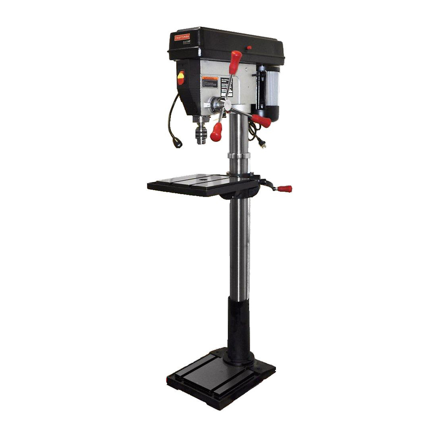
Operator's Manual
CRAFTSMAN"
1-1/2 HP (Maximum Developed)
16 Speeds (200-3630 R.P.M.)
5/8 Inch Chuck
17-INCH DRILL PRESS
Model No.
137.229171
CAUTION:
Before using this Drill Press,
read this manual and follow
all its Safety Rules and
Operating Instructions
•
Safety Instructions
•
Installation
•
Operation
•
Maintenance
•
Parts List
•
Espa5ol
I Customer
Help
Line
I
1400443-1682
Seam, Roebuck and Co., Hoffman Estates, IL 601_Td_Slalec,d
Visit our Craftsman webslte: www.sears.com/craftsman
Pa_ No. 137229171001
Advertisement
Table of Contents

Related Manuals for Craftsman REXON 137.229171


Summary of Contents for Craftsman REXON 137.229171
- Page 1 • Operation • Maintenance all its Safety Rules and • Parts List Operating Instructions • Espa5ol 1400443-1682 I Customer Help Line Seam, Roebuck and Co., Hoffman Estates, IL 601_Td_Slalec,d Visit our Craftsman webslte: www.sears.com/craftsman Pa_ No. 137229171001...
-
Page 2: Full One Year Warranty
SECTION PAGE Warranty ....................... Product Specifications ..................... Safety Instructions ....................Accessories and Attachments .................. Carton Contents ...................... Know Your Drill Press ....................Glossary of Terms ....................Assembly and Adjustment ..................Operation ......:..................Maintenance ......................Troubleshooting Guide .................... Parts ........................ -
Page 3: General Safety Instructions
GENERAL SAFETY INSTRUCTIONS REMOVE ADJUSTING KEYS AND WRENCHES, Form the habit of checking to see that keys and BEFORE USING THE DRILL PRESS adjusting wrenches are removed from the tool before turning "ON" Safety is a combination of common sense, staying alert and knowing how to use your drill press. - Page 4 SPECIFIC SAFETY INSTRUCTIONS 14. SECURE WORK. Use clamps or a vise to hold the FOR THE DRILL PRESS work when practical. It's safer than using your hand and it frees both hands to operate tool. WHEN using a drill press vise, always fasten to the table.
-
Page 5: Guidelines For Extension Cords
This tool is intended for use on a cimuit that has a GROUNDING INSTRUCTIONS receptacle like the one illustrated in FIGURE A RGURE A shows a 3-prong electrical plug and receptacle IN THE EVENT OF A MALFUNCTION OR BREAKDOWN, that has a grounding conductor. If a properly grounded grounding provides a path of least resistance for electric receptacle is not available, an adapter (FIGURE B) can current and reduces the risk of electric shock. -
Page 6: Available Accessories
AVAILABLE ACCESSORIES UNPACKING AND CHECKING CONTENTS Use only accessories recommended for this drill press. Follow instructions that accompany accessories. Use of If any part is missing or damaged, do not plug the drill improper accessories may cause hazards. press in until the missing or damaged part is replaced, and assembly is complete. - Page 7 r4_ =,...
- Page 8 Belt guard cover Belt pulleys Belt tension handle Belt tension lock knob Light switch Bert tension knob ON/OFF set screws -UPper stop nut Depth stop Motor - Spring cap Table Feed spring Cord clamp Rack Power cord Bevel scale Quill ,crank Table lock Table support lock...
- Page 9 DRILLING SPEED -Changed by placing the belt in any BASE - Supports the drill press. For additional stability,. holesare provided in the base to bolt the drill press to of the steps (grooves) in the pulleys. See the Spindle U_e floor.(See "Specific Safety Instructions for DriUPresses".) Speed Chart inside the belt guard.
-
Page 10: Tools Needed
ASSEMBLY INSTRUCTIONS INSTALUNG THE TABLE (FIG. B and C) Locate the table crank (1) and support lock (2) from the loose parts beg. Insert the support lock handle into the hole (3) at the rear of the table support assembly. Tighten by hand. For your own safety, never connect plug to power source Install the table crank handle onto the small outlet until all assembly and adjustment steps are... -
Page 11: Installing Feed Handles
INSTALLING THE HEAD (FIG. D) FENCE ASSEMBLY (RG. F) This drillpress has a channeled table top. Determine the desired locationfor the fenco (1). Slide the T-blocks(2) into_ appropriatechannels as TheDrill Press head is very heavy and MUST be lifted shown. withthe help of 2 PEOPLE OR MORE, to safely Align the mountingholes of the fence over the T-block's assemblethe Drill Press head on the column. -
Page 12: Installingthe Chuck
INSTALLINGTHE CHUCK(RG. G,H,andI 7. Using a rubber mallet, plastic-tipped hammer, or a 1, Cleanoutthetapered holeinthechuck(1)with block of wood and a hammer, firmly tap the chuck clean cloth. upward into position on the spindle shaft. Clean tapered surfaceson the ad_or(2) and spindle(3). Fig. - Page 13 DRILL PRESS ADJUSTMENTS Fig. L CAUTION: All the adjustments for the operation of the drillpress have been completed at the factory, Due to normal w ear and use, some occasional readjustments may be nesessary. IP_WkrlVl_,1-'l_l_'l Topreventpe_scoalinjury, always disconnectthe plug from •...
-
Page 14: Quill Return Spring
Fig. O To prevent personalinjury, always disconnectplug from the power source when making any adjustments. SPINDLE/QUILL (FIG. N) Rotate the feed handles counterclockwise to lower spindle to its lowest position. Hand support the spindle securely and move it back and forth around its axis. If there is too much play, do the following: Loosen the lock nut (1). - Page 15 To avoid injury from an accidental start, ALWAYS make sure the switch is in the =OFF" position, the switch key is removed,and the plug is not connected to the power sourceoutlet before making belt adjustments BASIC DRILL PRESS OPERATIONS ALIGNINGTHE BELT PULLEYS (RG.
- Page 16 ON / OFF SWITCH PANEL (FIG. S) Fig. T The "ON / OFF" switch has a removable, yellow plastic key. With the key removed from the switch, unauthorized and hazardous use by children and others is minimized. To turn the drill press "ON", insert key (1) into the slot of the switch (2), and move the switch upward to the "ON"...
- Page 17 LOCKING THE CHUCK AT THE DESIRED DEPTH DRILLING TO A SPECIRC DEPTH (RG. V) Drilling a blind hole (not all the way through workpiece) (RG. W) With the switch "OFF', turn the feed handles until the to a given depth can be done two ways: chuck (1) is at the desired depth.
- Page 18 BASIC OPERATION INSTRUCTIONS Use the SPINDLE SPEED recommended for the specific operation and workpiece material. Check the panel on the inside pulley cover or the chart To get the best results and minimize the likelihood of belowfor drillingspeed information. For accessories, personal injury, follow these instructionsfor operating your refer to the instructions provided with each drill press.
-
Page 19: Tilting Thetable
HOLDING A DRILLING LOCATION POSITIONING THE TABLE ANDWORKPIECE (FIG.Y, Using a centerpunch or sharp nail, make an indentation and Z) in the workpiece where you want the hole. Lock the table (I) to the column (2) at a position so the tip of the drill bit (3) is just above the top of the Using the feed handles, bang the ddll down to align with the indentation before turning the drill ON,... -
Page 20: Maintaining Your Drill Press
MAINTAINING YOUR DRILL PRESS To avoid shock or fire hazard, if the power cord is worn m L_ri1_]_qlLEe] or cut in any way, have it replaced immediately. For your own safety, turn the switch "OFF' and remove LUBRICATION the plug from the power source outlet before maintaining or lubricating your drill press. -
Page 21: Troubleshooting
TROUBLESHOOTING GUIDE To avoid injury from an accidental start, turn the switch "OFF" and always remove the plug from the power source before making any adjustments. • Consult your local Sears Service Center if for any reason the motor will not run. PROBLEM PROBABLE CAUSE REMEDY... - Page 22 17" DRILL PRESS PARTS LIST MODEL NO. 137.229171 When servicing use only CRAFTSMAN replacement parts. Use of any other parts may create a HAZARD or cause product damage, Any attempt to repair or replace electrical parts on this Drill Press may create a HAZARD unless repair is done by a qualified service technician.
- Page 23 17" DRILL PRESS PARTS LIST MODEL NO. 137.229171 05YS 22AY OSGG 05XK 072B 0°TS OIGPV OKPX 05Z2 0SGF O.13M 05YD OIQO 0714 0KQ5...
- Page 25 Get it fixed, at your home or ours! Your Home For repair-in your home-of all major brand appliances, lawn and garden equipment, or heating and cooling systems, no matter who made it, no matter who sold it! For the replacement parts, accessories and Operator's Manuals that you need to do-it-yourself For Sears professional installation of home apphances and items hke garage door openers and water heaters.