Kenwood NEXEDGE NX-220 Instruction Manual
Vhf/uhf digital transceiver
Hide thumbs
Also See for NEXEDGE NX-220:
- Service manual (118 pages) ,
- Instruction manual (42 pages) ,
- Instruction manual (72 pages)
Table of Contents
Advertisement
NX-220/ NX-320
VHF DIGITAL TRANSCEIVER/ UHF DIGITAL TRANSCEIVER
INSTRUCTION MANUAL
ÉMETTEUR-RÉCEPTEUR NUMÉRIQUE VHF/ ÉMETTEUR-RÉCEPTEUR NUMÉRIQUE UHF
MODE D'EMPLOI
TRANSCEPTOR DIGITAL VHF/ TRANSCEPTOR DIGITAL UHF
MANUAL DE INSTRUCCIONES
RICETRASMETTITORE DIGITALE VHF/ RICETRASMETTITORE DIGITALE UHF
MANUALE DI ISTRUZIONI
VHF DIGITAL FUNKGERÄT/ UHF DIGITAL FUNKGERÄT
BEDIENUNGSANLEITUNG
VHF DIGITALE ZENDONTVANGER/ UHF DIGITALE ZENDONTVANGER
GEBRUIKSAANWIJZING
VHF SAYISAL EL TELSİZİ/ UHF SAYISAL EL TELSİZİ
KULLANIM KILAVUZU
ΨΗΦΙΑΚΟΣ ΠΟΜΠΟΔΕΚΤΗΣ VHF/ ΨΗΦΙΑΚΟΣ ΠΟΜΠΟΔΕΚΤΗΣ UHF
ΟΔΗΓΙΕΣ ΧΡΗΣΗΣ
© B62-2319-00 (E)
09 08 07 06 05 04 03 02 01 00
Advertisement
Table of Contents

Related Manuals for Kenwood NEXEDGE NX-220


Summary of Contents for Kenwood NEXEDGE NX-220
-
Page 1: Instruction Manual
NX-220/ NX-320 VHF DIGITAL TRANSCEIVER/ UHF DIGITAL TRANSCEIVER INSTRUCTION MANUAL ÉMETTEUR-RÉCEPTEUR NUMÉRIQUE VHF/ ÉMETTEUR-RÉCEPTEUR NUMÉRIQUE UHF MODE D’EMPLOI TRANSCEPTOR DIGITAL VHF/ TRANSCEPTOR DIGITAL UHF MANUAL DE INSTRUCCIONES RICETRASMETTITORE DIGITALE VHF/ RICETRASMETTITORE DIGITALE UHF MANUALE DI ISTRUZIONI VHF DIGITAL FUNKGERÄT/ UHF DIGITAL FUNKGERÄT BEDIENUNGSANLEITUNG VHF DIGITALE ZENDONTVANGER/ UHF DIGITALE ZENDONTVANGER GEBRUIKSAANWIJZING... - Page 2 VHF DIGITAL TRANSCEIVER/ UHF DIGITAL TRANSCEIVER NX-220/ NX-320 INSTRUCTION MANUAL NOTIFICATION This equipment complies with the essential requirements of Directive 1999/5/EC. The use of the warning symbol means the equipment is subject to restrictions of use in certain countries. This equipment requires a licence and is intended for use in the countries as below.
- Page 3 Notice: The sign "Pb" below the symbol for batteries indicates that this battery contains lead. Firmware Copyrights The title to and ownership of copyrights for firmware embedded in Kenwood product memories are reserved for Kenwood Corporation.
-
Page 4: Thank You
THANK YOU We are grateful you have chosen Kenwood for your land mobile radio applications. This instruction manual covers only the basic operations of your NEXEDGE portable radio. Ask your dealer for information on any customized features they may have added to your radio. - Page 5 Ensure that there are no metallic items located between the transceiver and the battery pack. • Do not use options not specified by Kenwood. • If the die-cast chassis or other transceiver part is damaged, do not touch the damaged parts.
- Page 6 • If an abnormal odor or smoke is detected coming from the transceiver, switch the transceiver power off immediately, remove the battery pack from the transceiver, and contact your Kenwood dealer. • Use of the transceiver while you are driving may be against traffic laws.
- Page 7 Information concerning the battery pack: The battery pack includes flammable objects such as organic solvent. Mishandling may cause the battery to rupture producing flames or extreme heat, deteriorate, or cause other forms of damage to the battery. Please observe the following prohibitive matters.
- Page 8 • Do not charge the battery near fire or under direct sunlight! If the battery’s protection circuit is damaged, the battery may charge at extreme current (or voltage) and an abnormal chemical reaction may occur. The battery may generate heat or smoke, rupture, or burst into flame.
- Page 9 • Do not reverse-charge or reverse-connect the battery! The battery pack has positive and negative poles. If the battery pack does not smoothly connect with a charger or operating equipment, do not force it; check the polarity of the battery. If the battery pack is reverse-connected to the charger, it will be reverse- charged and an abnormal chemical reaction may occur.
-
Page 10: Table Of Contents
ADVANCED OPERATIONS .............. 23 BACKGROUND OPERATIONS ............28 UNPACKING AND CHECKING EQUIPMENT Note: These unpacking instructions are for use by your Kenwood dealer, an authorized Kenwood service facility, or the factory. Carefully unpack the transceiver. If any items are missing or damaged, file a claim with the carrier immediately. -
Page 11: Preparation
PREPARATION INSTALLING/ REMOVING THE (OPTIONAL) BATTERY PACK 1 Match the guides of the battery pack with the grooves on the upper rear of the transceiver, then firmly press the battery pack in place. 2 Lock the safety catch to prevent accidentally releasing the battery pack. - Page 12 Note: ◆ If you do not plan to use the transceiver for a long period, remove the batteries from the battery case. ◆ This battery case has been designed for transmitting at a power of approximately 1 W (the low power setting on your transceiver).
- Page 13 INSTALLING THE BELT CLIP Note: When first installing the belt clip, you must remove the battery pack from the rear of the transceiver. 1 Remove the 2 screws from the Plastic rear of the transceiver, then covering remove the small, plastic black covering that was held in place.
- Page 14 2 While holding the cap in place, push it towards the bottom of the transceiver until the tabs on the cap click into place. • To remove the cap, hold the top of the cap in place with your finger while inserting a 3 mm or smaller flat blade screwdriver under the bottom of the cap.
-
Page 15: Orientation
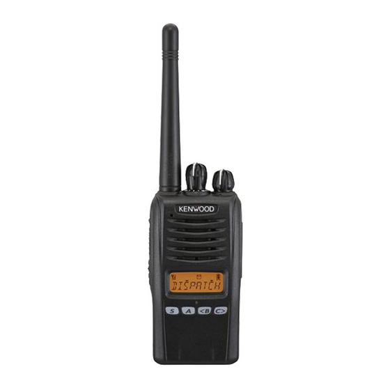
ORIENTATION There are 3 types of transceivers available: Type I: Equipped with a display and full keypad. Type II: Equipped with a display and 4-key keypad (S, A, <B, and C>). Type III: Basic model. Type I Antenna Microphone Battery pack Speaker Type II Antenna... - Page 16 Type III Antenna Microphone Battery pack Speaker Transmit/ Receive/ Battery low indicator If enabled by your dealer, lights red while transmitting, green while receiving a call (Conventional channels only), and orange when receiving an optional signaling call. Blinks red when the battery power is low while transmitting. Selector knob Rotate to select a zone or channel/group ID (default).
- Page 17 Side 2 key Press to activate its programmable function {page 10}. Types I and II: The default setting is [Backlight]. Type III: The default setting is [None] (no function). S, A, <B, C> keys (Types I and II only) Press to activate its programmable functions {page 10}. S key: The default setting is [None] (no function).
- Page 18 DISPLAY (TYPES I AND II ONLY) Indicator Description Signal strength indicator {page 29}. Monitor or Squelch Off is activated. Blinks when an incoming call matches your Optional Signaling. Talk Around is activated. Scan is in progress. Blinks while scan is paused.
-
Page 19: Programmable Auxiliary Functions
PROGRAMMABLE AUXILIARY FUNCTIONS The Selector, Auxiliary (orange), Side 1, Side 2, S, A, <B, and C> keys, as well as the Keypad, can be programmed with the functions listed below. Please contact your dealer for further details on these functions. •... - Page 20 • Stack • Zone Delete/Add • Status • Zone Down • Talk Around • Zone Select • Transceiver Password • Zone Up • Available only for Types I and II. Available only for Type III. Available only for NXDN Trunking operation. Can be programmed only on the Selector.
-
Page 21: Basic Operations
BASIC OPERATIONS SWITCHING POWER ON/OFF Turn the Power switch/ Volume control clockwise to switch the transceiver ON. Turn the Power switch/ Volume control counterclockwise fully to switch the transceiver OFF. ■ Transceiver Password (Types I and II Only) If your transceiver is password protected, you must first enter the password before you can use the transceiver. - Page 22 TRANSMITTING 1 Select the desired zone and channel/group ID. 2 Press the key programmed as [Monitor] or [Squelch Off] to check whether or not the channel is free. • If the channel is busy, wait until it becomes free. 3 Press the PTT switch and speak into the microphone. Release the PTT switch to receive.
- Page 23 RECEIVING Select the desired zone and channel. If signaling has been programmed on the selected channel, you will hear a call only if the received signal matches your transceiver settings. Note: Signaling allows your transceiver to code your calls. This will prevent you from listening to unwanted calls. Refer to “SIGNALING”...
-
Page 24: Scan
SCAN Scan monitors for signals on the transceiver channels. While scanning, the transceiver checks for a signal on each channel and only stops if a signal is present. To begin scanning, press the key programmed as [Scan]. • indicator appears (types I and II only). •... - Page 25 SCAN REVERT The Scan Revert channel is the channel selected when you press the PTT switch to transmit during scan. Your dealer can program one of the following types of Scan Revert channels: • Selected: The last channel selected before scan. •...
-
Page 26: Fleetsync: Alphanumeric 2-Way Paging Function
FleetSync: ALPHANUMERIC 2-WAY PAGING FUNCTION FleetSync is an Alphanumeric 2-way Paging Function, and is a protocol owned by Kenwood Corporation. Note: This function is available only in analog operation. SELCALL (SELECTIVE CALLING) A Selcall is a voice call to a station or group of stations. - Page 27 STATUS MESSAGE (TYPES I AND II ONLY) You can send and receive 2-digit Status messages which may be decided in your talk group. Messages can contain up to 16 alphanumeric characters. Status messages range from 10 to 99 (80 ~ 99 are reserved for special messages). A maximum of 15 received messages (combined status messages and short messages) can be stored in the stack memory of your transceiver.
- Page 28 ■ Reviewing Messages in the Stack Memory 1 Press the key programmed as [Stack], or press and hold the key programmed as [Selcall], [Status], or [Selcall + Status] to enter Stack mode. • The last received message is displayed. 2 Press the <B or C> key to select the desired message. •...
-
Page 29: 5-Tone Signaling
5-TONE SIGNALING 5-tone Signaling is enabled or disabled by your dealer. This function opens the squelch only when the transceiver receives the 5 tones programmed in your transceiver. Transceivers that do not transmit the correct tones will not be heard. SELCALL (SELECTIVE CALLING) (Types I and II Only) A Selcall is a voice call to a station or group of stations. - Page 30 STATUS MESSAGE (TYPES I AND II ONLY) You can send and receive Status messages which may be decided in your talk group. Messages can contain up to 16 alphanumeric characters. A maximum of 15 received messages can be stored in the stack memory of your transceiver.
-
Page 31: Reviewing Messages In The Stack Memory
■ Reviewing Messages in the Stack Memory 1 Press the key programmed as [Stack] to enter Stack mode. • The last received message is displayed. 2 Press the <B or C> key to select the desired message. • Press and hold the S or key for 1 second to cycle the display information as follows: Selcall Name >... -
Page 32: Advanced Operations
ADVANCED OPERATIONS DTMF (DUAL TONE MULTI FREQUENCY) CALLS ■ Making a DTMF Call (Types I and II Only) Manual Dialing (Type I Only) 1 Press and hold the PTT switch. 2 Enter the desired digits using the DTMF keypad. • If you release the PTT switch, transmit mode will end even if the complete number has not been sent. -
Page 33: Emergency Mode
■ Stun Code This function is used when a transceiver is stolen or lost. When the transceiver receives a call containing a stun code, the transceiver becomes disabled. The stun code is cancelled when the transceiver receives a call with a revive code. - Page 34 Pressing the PTT switch after the Scrambler function has been turned ON encrypts the transmitted signal. Note: This function cannot be used in certain countries. Contact your Kenwood dealer for further information. SIGNALING ■ Quiet Talk (QT)/ Digital Quiet Talk (DQT) Your dealer may have programmed QT or DQT signaling on your transceiver channels.
- Page 35 4 Press the S key to save your new setting. 5 When you have finished operating using OST, press the [OST] key again to turn the OST function OFF. ■ Radio Access Number (RAN) RAN is a new signaling system designed for digital radio communications.
-
Page 36: Vox Operation
■ VOX Gain Level (Types I and II Only) 1 Connect the headset to the transceiver. 2 Press the key programmed as [VOX]. • The current VOX Gain level appears on the display. 3 Press the <B or C> key to increase or decrease the VOX Gain level. -
Page 37: Background Operations
BACKGROUND OPERATIONS Your dealer can activate a variety of transceiver functions to perform without any additional operation on your part. TIME-OUT TIMER (TOT) The Time-out Timer prevents you from using a channel for an extended duration. If you continuously transmit for a preset time, the transceiver will stop transmitting and an alert tone will sound. - Page 38 ■ Battery Indicator (Types III Only) Press the key programmed as [Battery Indicator]. The LED lights for 2 seconds, displaying the battery power remaining, as described in the table below. When the battery power is very low, recharge or replace the battery pack. Lights Green Lights Orange Lights Red...
- Page 39 CONTROL CHANNEL HUNT On digital Trunking channels, the transceiver automatically searches for a control channel. • While searching for a control channel, the antenna icon will flash (types I and II only) and no signals can be received. PTT ID PTT ID is the transceiver unique ID code which is sent each time the PTT switch is pressed and/or released.