Table of Contents
Advertisement
Advertisement
Table of Contents

Related Manuals for HP mt41


Summary of Contents for HP mt41
- Page 1 HP mt41 Mobile Thin Client Maintenance and Service Guide...
- Page 2 By installing, copying, downloading, or otherwise using any software product preinstalled on this computer, you agree to be bound by the terms of the HP End User License Agreement (EULA). If you do not accept these license terms, your sole...
- Page 3 Important Notice about Customer Self-Repair Parts CAUTION: Your computer includes Customer Self-Repair parts and parts that should only be accessed by an authorized service provider. See Chapter 5, "Removal and replacement procedures for Customer Self-Repair parts," for details. Accessing parts described in Chapter 6, "Removal and replacement procedures for Authorized Service Provider only parts,"...
- Page 4 Important Notice about Customer Self-Repair Parts...
- Page 5 Safety warning notice WARNING! To reduce the possibility of heat-related injuries or of overheating the computer, do not place the computer directly on your lap or obstruct the computer air vents. Use the computer only on a hard, flat surface. Do not allow another hard surface, such as an adjoining optional printer, or a soft surface, such as pillows or rugs or clothing, to block airflow.
- Page 6 Safety warning notice...
-
Page 7: Table Of Contents
Table of contents 1 Product description ............................1 2 External component identification ........................ 4 Top ............................... 4 TouchPad ..........................4 Lights ........................... 5 Buttons and speakers ......................6 Keys ............................. 7 Front ..............................8 Right ..............................9 Left ..............................10 Display .............................. - Page 8 Function button board ......................75 Smart card reader ......................77 TouchPad button board ..................... 79 7 Computer Setup (BIOS), MultiBoot, and HP PC Hardware Diagnostics (UEFI) ........81 Using Computer Setup ........................81 Starting Computer Setup ....................81 Navigating and selecting in Computer Setup ..............81 Restoring factory settings in Computer Setup ..............
- Page 9 Using HP PC Hardware Diagnostics (UEFI) (select models only) ............. 86 Downloading HP PC Hardware Diagnostics (UEFI) to a USB device ....... 86 8 Specifications ..............................88 Computer specifications ........................88 9 Statement of Volatility ..........................89 Non-volatile memory usage ........................ 90 Questions and answers ........................
-
Page 11: Product Description
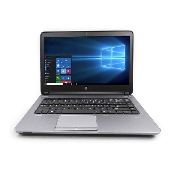
Product description Category Description Product Name HP mt41 Mobile Thin Client ● Processors AMD A4-5150M with Radeon HD 8350G Graphics (dual-core; 3.3 GHz/2.7 GHz; 35 W; 1 MB L2 cache) ● AMD A4-4300M with Radeon HD 7420G Graphics (dual-core; 3.0 GHz/2.5 GHz;... -
Page 12: Chapter 1 Product Description
● HP lt4112 LTE/HSPA+ Mobile Broadband Module Support for no WWAN option External media cards HP 2-in-1 multiformat Digital Media Reader Slot. Reads data from and writes data to digital memory cards such as Secure Digital (SD). ● Ports AC adapter, HP Smart ●... - Page 13 Category Description Support for the following batteries ● 9 cell, 100 Whr, 3.0 Ahr, Li-ion battery ● 6 cell, 55 Whr, 2.55 Ahr, Li-ion battery Security Supports security lock Trusted platform module (TPM) 1.2 (Infineon; soldered down) Preboot Authentication (Password, smart card) Integrated smart card reader Operating system Preinstalled:...
-
Page 14: External Component Identification
External component identification TouchPad Component Description TouchPad on/off button Turns the TouchPad on and off. TouchPad zone Moves the pointer and selects or activates items on the screen. Left TouchPad button Functions like the left button on an external mouse. Right TouchPad button Functions like the right button on an external mouse. -
Page 15: Lights
Lights Component Description ● Power light On: The computer is on. ● Blinking: The computer is in the Sleep state. ● Off: The computer is off. Caps lock light On: Caps lock is on. ● TouchPad light Amber: The TouchPad is off. ●... -
Page 16: Buttons And Speakers
Buttons and speakers Component Description ● Power button When the computer is off, press the button to turn on the computer. ● When the computer is on, press the button briefly to initiate Sleep. ● When the computer is in the Sleep state, press the button briefly to exit Sleep. -
Page 17: Keys
Keys Component Description Displays system information when pressed in combination with the key. Executes frequently used system functions when pressed in combination with a function key, the num lk key, or the key. Windows key Displays the Windows Start menu. Function keys Execute frequently used system functions when pressed in combination with the... -
Page 18: Front
Front Component Description ● Wireless light White: An integrated wireless device, such as a wireless local area network (WLAN) device is on. ● Amber: All wireless devices are off. ● Power light On: The computer is on. ● Blinking: The computer is in the Sleep state. ●... -
Page 19: Right
For additional safety information, see the Regulatory, Safety and Environmental Notices. To access the user guides, select Start > Hewlett-Packard > HP Documentation. NOTE: When a device is connected to the jack, the computer speakers are disabled. -
Page 20: Left
Left Component Description Power connector Connects an AC adapter. RJ-45 (network) jack Connects a network cable. ● RJ-45 (network) lights (2) Amber (left): The network is showing activity. ● Green (right): The network is connected. USB charging port Connects an optional USB device. The USB charging port can also charge select models of cell phones and MP3 players, even when the computer is off. -
Page 21: Display
To see wireless regulatory notices, see the section of the Regulatory, Safety and Environmental Notices that applies to your country or region. To access the user guides, select Start > Hewlett-Packard > HP Documentation. Display... -
Page 22: Bottom
Bottom Component Description Service door Provides access to the hard drive bay, the WLAN module slot, the WWAN module slot, and the memory module slots. CAUTION: To prevent an unresponsive system, replace the wireless module only with a wireless module authorized for use in the computer by the governmental agency that regulates wireless devices in your country or region. -
Page 23: Labels
Component Description Optional security screw Locks the service door release latch in place. Service door release latch open position Releases the service door on the computer. Battery bay Holds the battery. Vents (4) Enable airflow to cool internal components. NOTE: The computer fan starts up automatically to cool internal components and prevent overheating. - Page 24 Component Warranty period Model number (select models only) Serial number Product number ● Regulatory label(s)—Provide(s) regulatory information about the computer. ● Wireless certification label(s)—Provide(s) information about optional wireless devices and the approval markings of some of the countries or regions in which the devices have been approved for use.
-
Page 25: Illustrated Parts Catalog
Illustrated parts catalog Computer major components NOTE: Details about your computer, including model, serial number, product key, and length of warranty, are on the service tag at the bottom of your computer. See Labels on page 13 for details. Computer major components... - Page 26 Item Component Spare part number Display assembly: The display assembly is spared at the subcomponent level only. For more display assembly spare part information, see Display assembly subcomponents on page 14.0 in (35.56 cm), HD display assembly equipped with a webcam Chapter 3 Illustrated parts catalog...
- Page 27 Item Component Spare part number 14.0 in (35.56 cm), HD display assembly not equipped with a webcam Keyboard (includes keyboard cable): For use in Belgium 738687-A41 For use in Brazil 738687-201 For use in Bulgaria 738687-261 For use in Canada 738687-DB1 For use in the Czech Republic and Slovakia 738687-FL1...
- Page 28 Item Component Spare part number For use in the United States 738687-001 Keyboard bumper (included with TouchPad button board, spare part number 738407-001) Power connector cable 738683-001 Top cover 738405-001 TouchPad button board, 2 button with bracket (includes keyboard bumper) 738407-001 Smart card reader (include cable, shield, and tape) 738398-001...
- Page 29 Item Component Spare part number (22) WWAN module: HP lt4111 LTE/EV-DO/HSPA+ Mobile Broadband Module 704030-001 HP lt4112 LTE/HSPA+ Mobile Broadband Module 704031-001 (23) RTC battery (includes cable and double-sided adhesive) 651948-001 (24) Solid-state drive (SSD), 16 GB SATA (includes hard drive bracket, cable, and...
-
Page 30: Display Assembly Subcomponents
Display assembly subcomponents Item Component Spare part number Display bezel 738712-001 Microphone module Webcam/microphone module 738409-001 Microphone only module 738397-001 Display panel, 14 in (35.56 cm), WLED, HD, AG, SVA, flat display panel 747751-001 Left and right display hinges (included in Display Hinge Kit) 738396-001 Display panel cable (includes webcam/microphone module cable and tape) 738684-001... -
Page 31: Mass Storage Devices
738402-001) Miscellaneous parts Component Spare part number AC adapter: 65 W HP Smart adapter (PFC, 3-wire, 4.5 mm), select models only 693710-001 65 W HP Smart adapter (NPFC, 3-wire, 4.5 mm) 693711-001 Power cord (3-pin, black, 1.83 m): For use in Argentina... - Page 32 Component Spare part number For use in India 490371-D61 For use in Israel 490371-BB1 For use in Italy 490371-061 For use in Japan 490371-291 For use in North America 490371-001 For use in the People's Republic of China 490371-AA1 For use in South Africa 490371-AR1 For use in South Korea 490371-AD1...
-
Page 33: Sequential Part Number Listing
Atheros 802.11 b/g/n 1×1 + Bluetooth 4.0 Combo Adapter 691740-001 4 GB memory module (PC3L, 12800, 1600 MHz) 693710-001 65 W HP Smart adapter (PFC, 3 wire, 4.5 mm), select models only 693711-001 65 W HP Smart adapter (nPFC, 3 wire, 4.5 mm) 704030-001... - Page 34 Spare part Description number flag 718755-001 6 cell, 55 Whr, 2.55 Ahr, Li-ion battery 718757-001 9 cell, 100 Whr, 3.0 Ahr, Li-ion battery 730668-001 Broadcom 802.11 a/b/g/n 2×2 + Bluetooth 4.0 Combo Adapter 738396-001 Display Hinge Kit (includes left and right hinges) 738397-001 Microphone module 738398-001...
- Page 35 Spare part Description number flag 738687-171 Keyboard for use in Saudi Arabia (includes keyboard cable) 738687-201 Keyboard for use in Brazil (includes keyboard cable) 738687-211 Keyboard for use in Hungary (includes keyboard cable) 738687-251 Keyboard for use in Russia (includes keyboard cable) 738687-261 Keyboard for use in Bulgaria (includes keyboard cable) 738687-271...
-
Page 36: Removal And Replacement Procedures Preliminary Requirements
Removal and replacement procedures preliminary requirements Tools required You will need the following tools to complete the removal and replacement procedures: ● Flat-bladed screw driver ● Magnetic screw driver ● Phillips P0 and P1 screw drivers Service considerations The following sections include some of the considerations that you must keep in mind during disassembly and assembly procedures. -
Page 37: Cables And Connectors
Cables and connectors CAUTION: When servicing the computer, be sure that cables are placed in their proper locations during the reassembly process. Improper cable placement can damage the computer. Cables must be handled with extreme care to avoid damage. Apply only the tension required to unseat or seat the cables during removal and insertion. - Page 38 CAUTION: To prevent damage to the computer when you are removing or installing internal components, observe these precautions: Keep components in their electrostatic-safe containers until you are ready to install them. Before touching an electronic component, discharge static electricity by using the guidelines described in this section.
-
Page 39: Packaging And Transporting Guidelines
Packaging and transporting guidelines Follow these grounding guidelines when packaging and transporting equipment: ● To avoid hand contact, transport products in static-safe tubes, bags, or boxes. ● Protect ESD-sensitive parts and assemblies with conductive or approved containers or packaging. ● Keep ESD-sensitive parts in their containers until the parts arrive at static-free workstations. - Page 40 Equipment guidelines Grounding equipment must include either a wrist strap or a foot strap at a grounded workstation. ● When seated, wear a wrist strap connected to a grounded system. Wrist straps are flexible straps with a minimum of one megohm ±10% resistance in the ground cords. To provide proper ground, wear a strap snugly against the skin at all times.
-
Page 41: Removal And Replacement Procedures For Customer Self-Repair Parts
Removal and replacement procedures for Customer Self-Repair parts NOTE: The Customer Self-Repair program is not available in all locations. Installing a part not supported by the Customer Self-Repair program may void your warranty. Check your warranty to determine if Customer Self-Repair is supported in your location. Component replacement procedures NOTE: Please read and follow the procedures described here to access and replace Customer... -
Page 42: Battery
WARNING! To reduce potential safety issues, use only the user-replaceable battery provided with the computer, a replacement battery provided by HP, or a compatible battery purchased from HP. CAUTION: Removing a user-replaceable battery that is the sole power source for the computer can cause loss of information. -
Page 43: Service Door
Service door Description Spare part number Service door 738682-001 Service door, RCTO 748357-001 Before removing the service door, follow these steps: Turn off the computer. If you are unsure whether the computer is off or in Hibernation, turn the computer on, and then shut it down through the operating system. Disconnect the power from the computer by unplugging the power cord from the computer. -
Page 44: Hard Drive
Slide the service door toward the front of the computer (4), and then lift to remove the service door (5). Reverse this procedure to install the service door. Hard drive NOTE: The hard drive spare part kit includes the hard drive bracket, cable and screws. Description Spare part number 16 GB, SATA SSD... - Page 45 Remove the hard drive: Turn the computer upside down on a flat surface, with the battery bay toward you. Disconnect the hard drive cable (1). Loosen the four Phillips screws (2) connecting the hard drive to the computer. Using the plastic tab (3), pull and lift the hard drive, and then pull the hard drive (4) out of the hard drive bay.
-
Page 46: Optical Drive
Remove the bracket (3) from the hard drive. Reverse this procedure to install the hard drive. Optical drive NOTE: The optical drive spare part kit includes a bezel and bracket. Description Spare part number DVD-ROM drive (includes bezel bracket and screw) 744821-001 Optical drive weight saver (included with Plastics Kit, spare part number 738402-001) Before removing the optical drive, follow these steps:... - Page 47 Remove the optical drive or weight saver (3). Reverse this procedure to install the optical drive. Component replacement procedures...
-
Page 48: Wwan Module
WWAN module Description Spare part number HP lt4111 LTE/EV-DO/HSPA+ Mobile Broadband Module 704030-001 HP lt4112 LTE/HSPA+ Mobile Broadband Module 704031-001 CAUTION: To prevent an unresponsive system, replace the wireless module only with a wireless module authorized for use in the computer by the governmental agency that regulates wireless devices in your country or region. - Page 49 Remove the WWAN module (4) by pulling the module straight up. NOTE: If the WWAN antenna cables are not connected to the terminals on the WWAN module, protective sleeves should be installed on the antenna connectors, as shown in the following illustration.
-
Page 50: Wlan Module
WLAN module Description Spare part number Atheros 802.11 b/g/n 1×1 + Bluetooth 4.0 Combo Adapter 690019-001 Broadcom 802.11 a/b/g/n 2×2 + Bluetooth 4.0 Combo Adapter 730668-001 CAUTION: To prevent an unresponsive system, replace the wireless module only with a wireless module authorized for use in the computer by the governmental agency that regulates wireless devices in your country or region. - Page 51 The WLAN module tilts up. Remove the WLAN module (4) by pulling the module away from the slot at an angle. NOTE: If the WLAN antenna cables are not connected to the terminals on the WLAN module, protective sleeves should be installed on the antenna connectors, as shown in the following illustration.
-
Page 52: Memory Module
Memory module NOTE: Primary and expansion memory is installed in a stacked configuration in the bottom of the computer. Primary memory is installed in the bottom slot. Description Spare part number 4 GB (PC3L, 12800, 1600 MHz) 691740-001 Update BIOS before adding memory modules Before adding new memory, make sure you update the computer to the latest BIOS. - Page 53 Spread the retaining tabs (1) on each side of the memory module slot to release the memory module. (The memory module tilts up.) Remove the memory module (2) by pulling the module away from the slot at an angle. Reverse this procedure to install a memory module. Component replacement procedures...
-
Page 54: Fan
Description Spare part number 738685-001 Before removing the fan, follow these steps: Turn off the computer. If you are unsure whether the computer is off or in Hibernation, turn the computer on, and then shut it down through the operating system. Disconnect the power from the computer by unplugging the power cord from the computer. -
Page 55: Keyboard
Keyboard For use in country or region Spare part For use in country or region Spare part number number Keyboard (includes keyboard cable): For use in the Netherlands 738687-B31 For use in Belgium 738687-A41 For use in Northwest Africa 738687-FP1 For use in Brazil 738687-201 For use in Norway... - Page 56 Loosen the two captive screws that secure the keyboard to the computer. Open the computer facing toward you. Insert a thin tool (1) at the back of the keyboard to release the tabs, and then press on the back of the keyboard until the keyboard disengages from the computer. Push down on the keyboard, and then slide the keyboard (2) toward the front of the computer.
- Page 57 Release the ZIF connector (2) by lifting connector tab. Disconnect the keyboard cable (3) from the system board. Remove the keyboard (4). Reverse this procedure to install the keyboard. Component replacement procedures...
-
Page 58: Removal And Replacement Procedures For Authorized Service Provider Parts
Removal and replacement procedures for Authorized Service Provider parts CAUTION: Components described in this chapter should only be accessed by an authorized service provider. Accessing these parts can damage the computer or void the warranty. Component replacement procedures NOTE: Details about your computer, including model, serial number, product key, and length of warranty, are on the service tag at the bottom of your computer. -
Page 59: Display Panel
Display panel Description Spare part number Display bezel 738712-001 Display panel, 14 in (35.56 cm), WLED, HD, AG, SVA, flat display panel 747751-001 Before removing the display panel, follow these steps: Turn off the computer. If you are unsure whether the computer is off or in Hibernation, turn the computer on, and then shut it down through the operating system. - Page 60 Lift the top edge of the display panel (2). Swing the display panel (1) up and forward until it rests upside down in front of the display back cover. Release the adhesive strip (2) that secures the display panel cable connector to the display panel.
-
Page 61: Heat Sink Assembly
Heat sink assembly NOTE: The heat sink assembly spare part kit includes replacement thermal material. Description Spare part number Heat sink assembly (includes replacement thermal material) 738686-001 Before removing the heat sink assembly, follow these steps: Turn off the computer. If you are unsure whether the computer is off or in Hibernation, turn the computer on, and then shut it down through the operating system. - Page 62 NOTE: The thermal material must be thoroughly cleaned from the surfaces of the heat sink assembly and the system board components each time the heat sink assembly is removed. Replacement thermal material is included with the heat sink assembly, processor, and system board spare part kits.
-
Page 63: Processor
Processor NOTE: The processor spare part kit includes replacement thermal material. Description Spare part number AMD A4-5150M with Radeon HD 8350G Graphics (dual-core; 3.3 GHz/2.7 GHz; 35 W; 1 MB L2 713549-001 cache) AMD A4-4300M with Radeon HD 7420G Graphics (dual-core; 3.0 GHz/2.5 GHz; 35 W; 1 MB L2 685990-001 cache) Before removing the processor, follow these steps:... - Page 64 Lift the processor (2) straight up, and remove it. NOTE: The gold triangle (3) on the processor must be aligned with the triangle icon (4) embossed on the processor socket when you install the processor. Reverse this procedure to install the processor. Chapter 6 Removal and replacement procedures for Authorized Service Provider parts...
-
Page 65: Base Enclosure
Base enclosure Description Spare part number Base enclosure 738681-001 Before removing the bottom cover, follow these steps: Turn off the computer. If you are unsure whether the computer is off or in Hibernation, turn the computer on, and then shut it down through the operating system. Disconnect the power from the computer by unplugging the power cord from the computer. - Page 66 Remove the two Phillips screws (1) in the optical drive bay area, the nine Torx screws (2) on the front edge and rear corners and rear panel, the one Torx screw (3) in the fan area, the two Torx screws (4) in the memory module bay area and the one Torx screw (5) in the wireless module area that secure the base enclosure to the top cover.
- Page 67 Remove the base enclosure (2) from the top cover. Reverse this procedure to install the base enclosure. Component replacement procedures...
-
Page 68: Display Assembly
Display assembly Component Spare part number Display back cover (includes WWAN and WLAN antennas) 738680-001 Display bezel 738712-001 Display Hinge Kit (includes left and right hinges) 738396-001 Display panel, 14 in (35.56 cm), WLED, HD, AG, SVA, flat display panel 747751-001 Display panel cable (includes webcam/microphone module cable and tape) 738684-001... - Page 69 Remove the tape to release the wireless antenna cables (1) from the left speaker, and move the wireless cables out of the way. Disconnect the display panel cable (1) from the system board, and remove the display panel cable (2) from the routing on the right speaker. Turn the computer right-side up, with the battery bay toward you.
- Page 70 Remove the four Torx screws (1) that secure the top cover to the computer. Make sure the wireless cables (2) and display panel cable (3) feed cleanly through the openings. Remove the top cover (4) from the display assembly. If it is necessary to replace the display bezel or any of the LED display assembly subcomponents: Flex the inside edges of the top edge (1), the left and right sides (2), and the bottom edge (3) of the display bezel until the bezel disengages from the display enclosure.
- Page 71 If it is necessary to replace the display panel: Remove the four Phillips screws (1) that secure the display panel to the display enclosure. CAUTION: Before turning the display panel upside down, make sure the work surface is clear of tools, screws, and any other foreign objects. Failure to follow this caution can result in damage to the display panel.
- Page 72 If it is necessary to replace the webcam/microphone module or microphone module: CAUTION: Handle the webcam/microphone module or microphone module with caution. These modules have a thin profile and are susceptible to damage when not handled carefully. Lift the module (1) from the display back cover. (The module is attached to the display back cover with double-sided adhesive.) Detach the cable (2) from the module.
- Page 73 Release the right hinge snaps (1) and remove the hinges (2). If it is necessary to replace the display panel cable: Reverse this procedure to reassemble and install the display assembly. Component replacement procedures...
-
Page 74: Usb Board
USB board Description Spare part number USB board 738400-001 Before removing the USB board, follow these steps: Turn off the computer. If you are unsure whether the computer is off or in Hibernation, turn the computer on, and then shut it down through the operating system. Disconnect the power from the computer by unplugging the power cord from the computer. -
Page 75: Speakers
Speakers Description Spare part number Speakers (includes left and right speakers and tape) 738404-001 Before removing the speakers, follow these steps: Turn off the computer. If you are unsure whether the computer is off or in Hibernation, turn the computer on, and then shut it down through the operating system. Disconnect the power from the computer by unplugging the power cord from the computer. -
Page 76: Power Connector Cable
Remove the speakers (3) and (6). Reverse this procedure to install the speakers. Power connector cable Description Spare part number Power connector cable 738683-001 Before removing the power connector cable, follow these steps: Turn off the computer. If you are unsure whether the computer is off or in Hibernation, turn the computer on, and then shut it down through the operating system. - Page 77 Remove the power connector cable: Position the top cover upside down, with the battery bay facing you. Remove the Torx screw (1) from the base enclosure. Remove the power connector cable (2) from the base enclosure. Reverse this procedure to install the power connector cable. Component replacement procedures...
-
Page 78: Power Button Board
Power button board Description Spare part number Power button board (includes cable) 738399-001 Before removing the power button board, follow these steps: Turn off the computer. If you are unsure whether the computer is off or in Hibernation, turn the computer on, and then shut it down through the operating system. -
Page 79: System Board
System board NOTE: The system board spare part kit includes replacement thermal material. Description Spare part number For use only on computer models equipped with a WWAN 746017-001 For use only on computer models not equipped with a WWAN 746018-001 Before removing the system board, follow these steps: Turn off the computer. - Page 80 Disconnect the following from the system board: (1) Power button board ZIF connector (2) Function button board reverse ZIF connector Turn the top cover upside down. Chapter 6 Removal and replacement procedures for Authorized Service Provider parts...
- Page 81 Disconnect the following cables from the system board: (1) Card reader ZIF connector (2) Power connector cable (3) Right speaker cable (4) Display panel cable (5) Left speaker cable Component replacement procedures...
- Page 82 Remove the two Torx screws connecting the system board to the top cover. Lift the middle left side (1) of the system board, and then remove the board (2) by sliding it up and to the left at an angle. Reverse this procedure to install the system board.
-
Page 83: Rtc Battery
RTC battery Description Spare part number RTC battery (includes cable and double-sided adhesive) 651948-001 Before removing the RTC battery, follow these steps: Turn off the computer. If you are unsure whether the computer is off or in Hibernation, turn the computer on, and then shut it down through the operating system. - Page 84 Detach the RTC battery (2) from the base enclosure. (The RTC battery is attached to the base enclosure with double-sided adhesive.) Remove the RTC battery and cable. Reverse this procedure to install the RTC battery. Chapter 6 Removal and replacement procedures for Authorized Service Provider parts...
-
Page 85: Function Button Board
Function button board Description Spare part number Function button board (includes cable) 738401-001 Before removing the function button board, follow these steps: Turn off the computer. If you are unsure whether the computer is off or in Hibernation, turn the computer on, and then shut it down through the operating system. - Page 86 Remove the function button board (3). Reverse this procedure to install the function button board. Chapter 6 Removal and replacement procedures for Authorized Service Provider parts...
-
Page 87: Smart Card Reader
Smart card reader Description Spare part number Smart card reader (includes cable, shield, and tape) 738398-001 Before removing the smart card reader, follow these steps: Turn off the computer. If you are unsure whether the computer is off or in Hibernation, turn the computer on, and then shut it down through the operating system. - Page 88 Slide the smart card reader shield (2) away from the edge of the computer, and then lift up the shield (3) to remove it. Release the ZIF connector (1) to which the smart card reader cable is attached. Lift the clip (2) that secures the smart card reader to the base enclosure. Release the clip (3).
-
Page 89: Touchpad Button Board
TouchPad button board Description Spare part number TouchPad button board (includes keyboard bumper) 738407-001 Before removing the TouchPad button board, follow these steps: Turn off the computer. If you are unsure whether the computer is off or in Hibernation, turn the computer on, and then shut it down through the operating system. - Page 90 Remove the TouchPad button board (3). Reverse this procedure to install the TouchPad button board. Chapter 6 Removal and replacement procedures for Authorized Service Provider parts...
-
Page 91: Computer Setup (Bios), Multiboot, And Hp Pc Hardware Diagnostics (Uefi)
Computer Setup (BIOS), MultiBoot, and HP PC Hardware Diagnostics (UEFI) Using Computer Setup Computer Setup, or Basic Input/Output System (BIOS), controls communication between all the input and output devices on the system (such as disk drives, display, keyboard, mouse, and printer). -
Page 92: Restoring Factory Settings In Computer Setup
Use the arrow keys to select Main > Save Changes and Exit, and then press enter. Your changes go into effect when the computer restarts. NOTE: Your password settings and security settings are not changed when you restore the factory settings. Chapter 7 Computer Setup (BIOS), MultiBoot, and HP PC Hardware Diagnostics (UEFI) -
Page 93: Updating The Bios
Updating the BIOS Updated versions of the BIOS may be available on the HP website. Most BIOS updates on the HP website are packaged in compressed files called SoftPaqs. Some download packages contain a file named Readme.txt, which contains information regarding installing and troubleshooting the file. -
Page 94: Using Multiboot
Boot Device Options menu. ● To use MultiBoot Express to set variable boot orders. This feature prompts you for a boot device each time the computer is turned on or restarted. Chapter 7 Computer Setup (BIOS), MultiBoot, and HP PC Hardware Diagnostics (UEFI) -
Page 95: Setting A New Boot Order In Computer Setup
Setting a new boot order in Computer Setup To start Computer Setup and set a boot device order that the computer uses each time it is turned on or restarted, follow these steps: Turn on or restart the computer, and then press while the “Press the ESC key for Startup Menu”... -
Page 96: Entering Multiboot Express Preferences
Using HP PC Hardware Diagnostics (UEFI) (select models only) HP PC Hardware Diagnostics is a Unified Extensible Firmware Interface (UEFI) that allows you to run diagnostic tests to determine if the computer hardware is functioning properly. The tool runs outside of the operating system to isolate hardware failures from issues that may be caused by the operating system or other software components. - Page 97 Select your computer model, and then select your operating system. In the Diagnostic section, click HP UEFI Support Environment. – or – Click Download, and then select Run. Using HP PC Hardware Diagnostics (UEFI) (select models only)
-
Page 98: Specifications
Specifications Computer specifications Metric U.S. Dimensions Width 34.0 cm 13.39 in Depth 23.7 cm 9.33 in Height (front to rear) 2.53 cm to 2.9 cm .99 in to 1.14 in Weight (computer equipped 6 cell battery and ODD 2.083 kg 4.59 lb weight saver) Weight (computer equipped 6 cell battery and ODD) -
Page 99: Statement Of Volatility
The steps below will remove personal data from the notebook PC, including the nonvolatile memory found in AMD-based system boards. Some of these steps are disclosed in the Maintenance & Service Guides available for HP PC products available on the product support pages at www.hp.com. -
Page 100: Non-Volatile Memory Usage
Code is updated writing data to this accessible) (keyboard, when the system BIOS is memory and is mouse, & updated. available on the HP battery website. Writing data to management) this ROM in an inappropriate manner can render the PC non- functional. - Page 101 PC factory. Code is updated memory and is configuration when the system BIOS is available on the HP data. updated. Configuration website. Writing data to data and settings are input this ROM in an using the F10 setup utility inappropriate manner or a custom utility.
-
Page 102: Questions And Answers
Questions and answers How can the BIOS settings be restored (returned to factory settings)? Turn on or restart the computer and press when prompted near the bottom of the display. Select Main, then select Restore defaults. Follow the on-screen instructions. Select Main, save changes and exit, then press Enter. -
Page 103: 10 Power Cord Set Requirements
10 Power cord set requirements The wide-range input feature of the computer permits it to operate from any line voltage from 100 to 120 V ac, or from 220 to 240 V ac. The 3-conductor power cord set included with the computer meets the requirements for use in the country or region where the equipment is purchased. -
Page 104: Requirements For Specific Countries And Regions
Requirements for specific countries and regions Country/region Accredited agency Applicable note number Argentina IRAM Australia Austria Belgium CEBEC Brazil ABNT Canada Chile Denmark DEMKO Finland FIMKO France Germany India Israel Italy Japan The Netherlands KEMA New Zealand SANZ Norway NEMKO The People's Republic of China Saudi Arabia SASO... - Page 105 Country/region Accredited agency Applicable note number The United States The flexible cord must be Type HO5VV-F, 3-conductor, 0.75 mm² conductor size. Power cord set fittings (appliance coupler and wall plug) must bear the certification mark of the agency responsible for evaluation in the country or region where it will be used.
-
Page 106: 11 Recycling
Follow the local laws and regulations in your area for battery disposal. HP encourages customers to recycle used electronic hardware, HP original print cartridges, and rechargeable batteries. For more information about recycling programs, see the HP Web site at http://www.hp.com/recycle. Chapter 11 Recycling... -
Page 107: Index
Index left side 10 DVD-ROM drive AC adapter, spare part numbers right side 9 removal 36 21, 23 top 4 spare part number 18, 21, 25 AC adapter/battery light 8 computer DVD±RW SuperMulti Double- antenna, spare part number 20, major components 15 Layer Drive specifications 88 precautions 27... - Page 108 headphone (audio-out) jack 9 drive 8 optical drive weight saver, spare heat sink assembly microphone mute 5 part number 18, 21, 36 removal 51 mute 5 spare part number 18, 24, 51 num lock 5 packaging guidelines 29 hinge optical drive 10 plastic parts, service removal 62 power 5, 8...
- Page 109 pointing device 2 setup utility USB board ports 2 navigating and selecting 81 removal 64 power requirements 2 restoring factory settings 82 spare part number 18, 24, 64 processor 1 slots USB legacy support 81 product name 1 security cable 9 USB port 9, 10 security 3 smart card 10...