Table of Contents
Advertisement
Advertisement
Table of Contents

Related Manuals for Fujitsu CELSIUS M720


Summary of Contents for Fujitsu CELSIUS M720
- Page 1 System Operating Manual CELSIUS M720 CELSIUS M730...
- Page 2 Thank you for buying an innovative product from Fujitsu. Latest information about our products, useful tips, updates etc. is available on our website: "http://www.fujitsu.com/fts/" You can find driver updates at: "http://support.ts.fujitsu.com/download" Should you have any technical questions, please contact: •...
- Page 4 Published by / Contact address in the EU Fujitsu Technology Solutions GmbH Mies-van-der-Rohe-Straße 8 80807 Munich, Germany "http://www.fujitsu.com/fts/" Copyright © Fujitsu Technology Solutions GmbH 2013. All rights reserved. Publication Date 07/2013 Order No.: A26361-K1399-Z320-1-7619, edition 3...
- Page 5 CELSIUS M720 CELSIUS M730 Operating Manual Your CELSIUS... Ports and operating elements Important notes Getting started Operation Troubleshooting and tips System expansions Technical data Index...
- Page 6 Trademarks Fujitsu, the Fujitsu logo and CELSIUS are registered trademarks of Fujitsu Limited or its subsidiaries in the United States of America and other countries. PS/2 is a registered trademark of International Business Machines, Inc.
-
Page 7: Table Of Contents
CELSIUS M720 ........ - Page 8 Index ................. . 72 Fujitsu...
-
Page 9: Your Celsius
You can access and view the required information using the Acrobat Reader program, which is also included on the DVD. If necessary, you can also print out the manuals. Validity of the Reference Manual This Reference Manual is valid for the following systems: • CELSIUS M720 • CELSIUS M730 Fujitsu... -
Page 10: Notational Conventions
"Safety information" • cross-references to an external source, e.g. a web address: For more information, go to "http://www.fujitsu.com/fts" • Names of CDs, DVDs and titles or designations for other materials, e.g.: "CD/DVD Drivers & Utilities" or "Safety/Regulations" manual indicates a key on the keyboard, e.g:... -
Page 11: Ports And Operating Elements
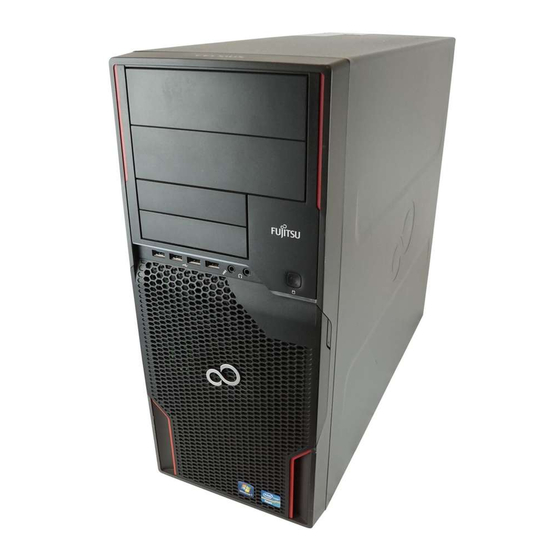
After this section, only the CELSIUS M730 is illustrated, as the procedure for both models is identical with the exception of the removal of the hard disk front panel. CELSIUS M720 Front 1 = Module bays for 5 "... -
Page 12: Rear
2 = Module bays for 3 " drives 6 = USB ports (2 x USB 3.0, 2 x USB 2.0) 3 = ON/OFF switch 7 = Hard disk front panel (removable) 4 = Headphone port 8 = Casing lock (optional) Fujitsu... -
Page 13: Rear
Ports and operating elements Rear 1 = Alternating voltage socket (AC IN) 3 = Slot covers 2 = Ports for external devices (device-dependent) Fujitsu... -
Page 14: Important Notes
If the device is brought from a cold environment into the room where it will be used, condensation may occur. To avoid damaging the device, wait until it has reached room temperature and is absolutely dry before initial startup. Fujitsu... -
Page 15: Cleaning The Device
Use disinfectant wipes to clean the keyboard and the mouse. Energy saving, disposal and recycling Disposal Energysaving Recycling Drivers& UtilitiesDVD User DocumentationDVD You can find information on these subjects on the "Drivers & Utilities" DVD or on our website ("http://www.fujitsu.com/fts/about/fts/environment-care/"). Fujitsu... -
Page 16: Ce Marking
Explanation: CE nnnn (!) ; nnnn defines the type of CE marking and the exclamation mark indicates a device with radio components. You can find more information and declarations of conformity on the Internet at: "http://globalsp.ts.fujitsu.com/sites/certificates". This equipment can be used in the following countries: Belgium... -
Page 17: Fcc Class B Compliance Statement
Fujitsu is not responsible for any radio or television interference caused by unauthorized modifications of this equipment or the substitution or attachment of connecting cables and equipment other than those specified by Fujitsu. The correction of interferences caused by such unauthorized modification, substitution or attachment will be the responsibility of the user. -
Page 18: Getting Started
Drives and boards If you have received drives or boards with your device, please do not install them until after first-time setup. How to install drives and boards is described in the "System expansions", Page 34 chapter. Fujitsu... -
Page 19: Setting Up The Device
► Connect the mains cable to the machine (1). ► Plug the mains plug into a three-pin socket (2). After the mains power cable has been attached, the device automatically switches itself on for a few seconds to run a system test, then switches off again. Fujitsu... -
Page 20: Connecting External Devices
Disconnecting cables ► Switch off all affected devices. Cable ► Remove power plugs from the mains outlets for all devices. ► Unplug all data communication cables from the utility sockets. ► Unplug all cables from the device and peripherals. Fujitsu... -
Page 21: Ports On The Device
LAN port green LANport Audiooutput Lineout USB - Universal Serial Bus, SCSI connection black UniversalSerialBus FireWire port 1394 Some of the connected devices require special software (e.g. drivers) (refer to the documentation for the connected device and operating system). Fujitsu... -
Page 22: Connecting A Monitor
Only attach the monitor to your device when it is switched off. ► Follow the instructions contained in the monitor manual to prepare the monitor for operation (e.g. connecting cables). ► Plug the data cable into a suitable monitor port of the device. Fujitsu... -
Page 23: Connecting The Mouse
► Plug the rectangular connector of the keyboard cable into the rectangular socket on the underside or on the rear of the keyboard. ► Plug the round plug of the keyboard cable into the keyboard port on the device. Keyboard, ► Switch your device on again. Fujitsu... -
Page 24: Connecting External Devices To The Usb Ports
Plan a reasonable amount of time for this, as this process must not be interrupted. You may need the licence number for Windows during the installation. The licence number is located on a label on your device. Fujitsu... -
Page 25: Switching On Monitor And Device
Help in your operating system. You will find more information on the system, as well as drivers, utilities and updates on the "Drivers & Utilities" DVD and on the Internet at "http://www.fujitsu.com/fts/support". You can find information and help on the Windows operating system functions on the Internet at "http://windows.microsoft.com". -
Page 26: Operation
The ON/OFF switch does not disconnect the device from the mains voltage. To completely disconnect the mains voltage, remove the power plug from the power socket. ► If necessary, switch the monitor off (see the operating manual for the monitor). Fujitsu... -
Page 27: Indicators On The Device
Operation Indicators on the device The indicators are on the front of the casing. Which indicators are available on your device depends on the configuration level you have selected. CELSIUS M720: CELSIUS M730: Fujitsu... - Page 28 ON/OFF switch. Hard disk indicator The indicator lights up when the hard disk drive in the device is being accessed. In energy-saving mode the device must not be disconnected from the mains supply, as data loss may occur. Fujitsu...
-
Page 29: Keyboard
With some keyboards the ON/OFF switch can only be used with an ACPI (Advanced Configuration and Power Management Interface). Otherwise the key is inoperative. The mainboard must support this function. Keys, Keys, Keys, Enter key confirms the highlighted selection. The Enter key is also referred to as the "Return" key. Fujitsu... -
Page 30: Settings In Bios Setup
In BIOS Setup, you can set the system functions and the hardware configuration of the device. When the PC is delivered, the default entries are valid (see "BIOS Setup" manual or manual for the mainboard). You can customise these settings to your requirements in the BIOS Setup. Fujitsu... -
Page 31: Property And Data Protection
(2) and a padlock and chain which you have connected to a fixed object beforehand. Lead-sealing To prevent unauthorised persons from opening the casing, the casing can be lead-sealed. To do this, feed the sealing chain through the holes (2) and seal the chain with the lead seal. Fujitsu... -
Page 32: Mechanical Casing Lock (Optional)
Protect the device from being switched on by an external device You can also combine these functions. You will find a detailed description of the Security menus and how to assign passwords in the manual for the mainboard or in the "BIOS Setup" manual. Fujitsu... -
Page 33: Access Authorisation Via Smartcard
Operation of this module is not permitted in Taiwan. ► Connect the external SmartCard reader to your system as described in the instructions for the SmartCard reader. SmartCard reader, After the device is switched on, you will be prompted to insert your SmartCard. Fujitsu... -
Page 34: Troubleshooting And Tips
► For further clarification of the problem, contact the Service Desk for your country (see the Service Desk list or visit the Internet at "http://support.ts.fujitsu.com/contact/servicedesk"). When you do this, please have ready the identity number and serial number of your system. -
Page 35: The Device Cannot Be Switched Off With The On/Off Switch
► Restart the system. Incorrect setting for the monitor ► Press while the system is booting. ► Start the system in Safe Mode. ► Set up the monitor as described in the documentation for your operating system and monitor. Fujitsu... -
Page 36: No Mouse Pointer Displayed On The Screen
Installing new software When installing programs or drivers, important files may be overwritten and modified. To be able to access the original data in the event of any problems following installation, you should backup your hard disk prior to installation. Fujitsu... -
Page 37: Restoring The Hard Disk Contents
You will find the instructions for restoring the contents of the hard disk in the "Recovery Guide" manual. Tips Topic Lack of system resources ► Close unnecessary applications. ► Run the applications in a different order. Other manuals Further manuals are provided as PDF files on the "Drivers & Utilities" DVD. Fujitsu... -
Page 38: System Expansions
An update of the BIOS may be required for a system expansion or hardware upgrade. Further information can be found in the BIOS help section or if necessary in the Technical Manual for the mainboard. Fujitsu... -
Page 39: Information About Boards
The equipment and tools you use must be free of static charges. • Only touch or hold the boards by the edge or, if present, at the areas marked green (Touch Points). • Never touch pins or conductors on boards fitted with ESDs. Fujitsu... -
Page 40: Opening The Casing
► On devices with a casing lock: Unlock the casing. ► Lay the device on its side in the manner shown. ► Pull the locking device (1) and swivel the side part in the direction of the arrow (2). Fujitsu... -
Page 41: Closing The Casing
" drives and two 2 " drives (optional) • or: eight 2 -inch drives (optional) "Accessible drives" are e.g. DVD or CD ROM drives, into which a data medium can be inserted from outside. "Non-accessible drives" are for example hard disk drives. Fujitsu... -
Page 42: Installing And Removing The Accessible 5
► Push the drive metal plate upwards (2) so it is released from the catches with which it is secured. ► Lift the drive cover away from the casing (3). ► Connect the drive cover to the drive (1). Fujitsu... -
Page 43: Installing An Accessible Drive
(1). ► Connect the cables to the drive. Make sure the polarity is correct. ► Close the casing (see "Closing the casing", Page 37). It may be necessary to modify the entry for the drive in the BIOS Setup. Fujitsu... -
Page 44: Removing An Accessible Drive
► Disconnect the cables connected to the drive. ► Slide the clip in the direction of the arrow (1). ► Pull the drive out of the casing in the direction of the arrow (2). ► Remove the drive cover from the drive (1). Fujitsu... -
Page 45: Installing/Removing A 3½" Reader In A 3½" Bay (Optional, Smartcard Or Multicard)
If you have ordered a device with a SmartCard or MultiCard reader, the module holder, SmartCard or MultiCard reader are already built in on delivery. If you have ordered a device without a SmartCard or MultiCard reader, a blind cover is installed instead of the module holder. Fujitsu... -
Page 46: Removing The Module Holder
Screwing the reader onto the module holder ► With the component side facing downwards, slide the reader in the direction of arrow (1) into the guide on the module holder (a). ► Fasten the reader with the screws (2). Fujitsu... -
Page 47: Installing A Module Holder With Reader
► Push the module holder into the casing in the direction of the arrow (1). ► Fasten the module holder with the screws (2). ► Connect the cables to the boards and the mainboard. Make sure the polarity is correct. ► Close the casing (see "Closing the casing", Page 37). Fujitsu... -
Page 48: Removing A Module Holder With Reader
Page ► Close the casing (see "Closing the casing", Page 37). Removing the reader from the module holder ► Undo the screws (1). ► Pull the reader out of the module holder in the direction of the arrow. Fujitsu... -
Page 49: Installing And Removing A Wlan Module (Optional)
To access the WLAN module bay, you need to remove the front fan after removing the front panel. The front fan is secured using several locking hooks that will need to be unlocked one after the other. ► Disconnect the fan cable from the mainboard. Fujitsu... - Page 50 ► Lift the lower locking lugs of the fan slightly (1). At the same time, slide the fan in direction of the arrow (2). ► To release the left-hand locking lug, push it in the direction of the arrow (3). Fujitsu...
-
Page 51: Installing The Wlan Module
► Remove the fan from the casing (6). Installing the WLAN module Remove the metal panel The slot for the WLAN module is protected by a metal cover on delivery. ► Break out the pre-stamped metal cover (1) with a screwdriver. Fujitsu... - Page 52 ► Slide the WLAN module into the slot in the direction of the arrow (1). Ensure that the screw holes on the casing and those on the WLAN module are precisely aligned over one another. ► Secure the WLAN module with the screws (2). ► Attach the cables to the WLAN module and mainboard. Fujitsu...
-
Page 53: Removing The Wlan Module
System expansions Removing the WLAN module ► Detach the cables from the WLAN module and mainboard. ► Undo the screws (1). ► Pull the WLAN module out of the bay the direction of the arrow (2). Fujitsu... -
Page 54: Installing The Front Fan
► Push the fan in the direction of the arrow (2) until the lower catches engage. ► Make sure that the two upper catches also engage. ► If necessary, reinstall the boards previously removed from the fan (see "Installing a board", Page 61). Fujitsu... - Page 55 ► Insert the upper part of the card holder in the guide (2) and push it to the edge of the guide. The upper part of the card holder engages. ► Connect the fan cable to the mainboard. ► Reattach the front panel (see "Securing the front panel", Page 52). Fujitsu...
-
Page 56: Securing The Front Panel
► Put the front cover onto the guide openings on the right of the casing. ► Fold the front panel in the direction of the arrow (1) until the catches (a) engage. ► Close the casing (see "Closing the casing", Page 37). Fujitsu... -
Page 57: Installing The Hard Disk Drive
2 inch drives and two 3 inch drives • or: four 3 -inch drives Standard installation kit Alternatively, you can purchase an optional installation kit in which you can install up to eight 2 -inch drives: Optional installation kit Fujitsu... -
Page 58: Replacing The Installation Kit
► Secure the drive cables on the installation kit again. ► If required, connect further drive cables with sufficient drive connectors to the installation kit and the mainboard. When connecting the cables, note the numbering on the installation kit and on the cables. Fujitsu... -
Page 59: Installing Hard Disks
The following images illustrate the installation of a 3 " drive. Removing the hard disk front panel CELSIUS M720 CELSIUS M730 ► Press the unlocking keys on the sides of the hard disk front panel (1). ► Fold the hard disk front panel in the direction of the arrow (2) and remove it from the casing. - Page 60 36). If you use a casing with a casing lock, the safety guard in front of the drives is also secured against unauthorised opening. • Requirement: remove the protective grille (see "Removing the protective grille", Page 56). EasyChange rails for a second hard disk drive are mounted on the drive cage. Fujitsu...
- Page 61 (1). Ensure that the label on the 3½" hard disk drive is facing the side cover to be opened. If you are installing a 2½" hard disk drive, ensure that the label is on the top. ► Connect the cables to the hard disk drive. Fujitsu...
-
Page 62: Removing A Hard Disk
► Press the levers of the EasyChange rails, which are secured to the hard disk drive, outwards (1) until the hard disk is released. ► Pull the hard disk drive out of the drive cage in the direction of the arrow (2). Fujitsu... - Page 63 ► Put the protective grille into the sheet metal lugs on the casing and fold it in the direction of the arrow (1). The protective grille is secured. ► Reattach the front panel to the casing (see "Securing the hard disk front panel", Page 60). Fujitsu...
- Page 64 System expansions Securing the hard disk front panel CELSIUS M720 CELSIUS M730 ► Place the hard disk front panel in the guide openings as illustrated. ► Fold the hard disk front panel in the direction of arrow (1) until you feel it engage.
-
Page 65: Installing And Removing A Board
► Push the retaining clip (1) towards the slot cover to unlock it, then move it towards the back panel of the device. ► Pull the slot cover out of the slot in the direction of the arrow (2). Fujitsu... - Page 66 ► Close the casing (see "Closing the casing", Page 37). If you have installed or removed a board, please check the relevant slot settings in the BIOS Setup. If necessary, change the settings. Further information is provided in the board documentation. Fujitsu...
-
Page 67: Removing A Board
► Push the retaining clip (1) towards the slot cover to unlock it, then move it towards back panel of the device. ► Pull the board out of the slot in the direction of the arrow (2). ► Place the board in suitable packaging. Fujitsu... -
Page 68: Upgrading Main Memory
"Installing the rear fan", Page 67). ► If the bays are located below the hard disk fan: Install the hard disk fan again (see "Install the hard disk fan", Page 69). ► Close the casing (see "Closing the casing", Page 37). Fujitsu... -
Page 69: Replacing The Processor
► Tighten the screws. ► Reinstall the hard disk fan and the hood of the hard disk fan (see "Install the hard disk fan", Page 69). Never attach or detach fans during operation. This can cause problems controlling the mainboard fan. Fujitsu... -
Page 70: Removing And Installing The Rear Fan
36). ► Disconnect the fan cable from the mainboard. ► Press the catch of the fan in the direction of the arrow (1) so that the fan releases from the location. ► Remove the fan from the casing (2). Fujitsu... -
Page 71: Removing And Installing The Hard Disk Fan
► Position the fan in the casing (1) and ensure that the catch (2) engages in the openings on the back of the device. ► Connect the fan cable to the mainboard. Removing and installing the hard disk fan To access the front main memory slots, you must remove the hard disk fan. Fujitsu... - Page 72 ► Unhook the hood. ► Remove the hood from the casing. ► Move the catches of the fan in the direction of the arrow (1) so that the fan releases from the location. ► Remove the fan from the casing (2). Fujitsu...
-
Page 73: Installing A 4 Port Sas Upgrade Rom
Proceed as follows to install the 4 port SAS upgrade ROM mass storage controller: ► Open the casing (see "Opening the casing", Page 36). ► Plug the upgrade ROM connector into the mainboard – refer to the mainboard manual for details. ► Close the casing (see "Closing the casing", Page 37). Fujitsu... -
Page 74: Replacing The Lithium Battery
► Press the catch in the direction of the arrow (1). The battery jumps out of the holder slightly. ► Remove the battery (2). ► Push the new lithium battery of the identical type into the holder (3) and press it down until it engages. Fujitsu... -
Page 75: Technical Data
4 A - 9.5 A Celsius M720 Power (800W PSU), 100 V – 240 V 2.5 A - 5.5 A Celsius M720 (500W PSU), 100 V – 240 V Dimensions Width/depth/height: 186 mm x 481 mm x 430 mm / 7.32 inches x 18.93 inches x 16.92 inches... -
Page 76: Index
Connecting a PS/2 keyboard 19 Connecting, Headphones 17 keyboard 19 mouse 19 PS/2 keyboard 19 PS/2 mouse 19 Important notes 10 USB keyboard 19 Installing, Contents of delivery 14 software 20–21 Cord switching on for the first time 20 Fujitsu... - Page 77 Mains adapter, Security measures 27 connecting 15 SecurityLock 27 Microphone jack 17 Servicing 34 Monitor port 17 Setup, Monitor, see BIOS Setup 26 switching off 22 SmartCard reader, switching on 21–22 operating 29 Mouse port 17 Software, Mouse, installing 20–21 Fujitsu...
- Page 78 20 BIOS Setup 26 USB port 19 System unit, see Device 11 USB port, connecting devices 20 connecting keyboard 19 connecting the mouse 19 Transportation 10–11 User Documentation DVD 11 Universal Serial Bus 17 Workstation 15 Upgrades, device 34 Fujitsu...