Table of Contents
Advertisement
Quick Links
SERVICE MANUAL
Ver. 1.0 2008.01
HD Radio Broadcasting was approved by the Federal
Communications Commission in October 2002 as the system for digital
AM and FM broadcasting in the U.S.
HD Radio technology features include:
– Static-free, clear radio reception.
– FM Multicasting – the ability to broadcast multiple program streams over
a single FM frequency.
– A variety of "data services," including text-based
information – artist name, song title, etc. scrolled across your
receiver display.
– Digital broadcasts in the same frequencies as analog
broadcasts; listeners do not need to learn a new station
number and today's stations remain at their current place on the dial.
HD Radio technology is developed and licensed by iBiquity Digital Corpo-
ration and supported by the leaders of the
broadcasting, consumer electronics and automotive industries.
TM
HD Radio
Technology Manufactured Under License From iBiquity Digi-
tal Corp. U.S. and Foreign Patents. HD Radio
proprietary trademarks of iBiquity Digital Corp.
Sony Corporation
9-887-972-01
2008A04-1
Audio Business Group
©
2008.01
Published by Sony Techno Create Corporation
TM
and the HD Radio logo are
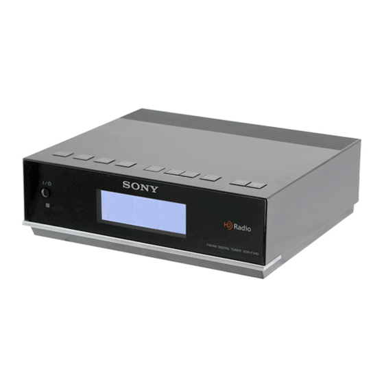
XDR-F1HD
SPECIFICATIONS
Time display
12-hour system
Frequency range
FM: 87.5 – 108 MHz
AM: 530 – 1,710 kHz
Audio output
Output level 0.7 Vrms at 47 kΩ
Recommended load impedance over 10 kΩ
75 Ω antenna terminal for FM
Antenna terminal
Antenna terminal for AM
Power requirements
120 V AC, 60 Hz
Dimensions
Approx. 180 × 60 × 160 mm (w/h/d)
1
(7
/
× 2
3
8
parts and controls
Mass
Approx. 1.1 kg (2 lb 6.8 oz)
Supplied accessories
Remote commander (1)
FM dipole antenna (1)
AM loop antenna (1)
Design and specifi cations are subject to change
without notice.
FM/AM DIGITAL TUNER
US Model
3
/
× 6
/
inches) not incl. projecting
8
8
Advertisement
Table of Contents

Related Manuals for Sony XDR-F1HD


Summary of Contents for Sony XDR-F1HD
- Page 1 Technology Manufactured Under License From iBiquity Digi- tal Corp. U.S. and Foreign Patents. HD Radio and the HD Radio logo are proprietary trademarks of iBiquity Digital Corp. FM/AM DIGITAL TUNER Sony Corporation 9-887-972-01 2008A04-1 Audio Business Group © 2008.01 Published by Sony Techno Create Corporation...
-
Page 2: Table Of Contents
COMPONENTS IDENTIFIED BY MARK 0 OR DOTTED LINE WITH MARK 0 ON THE SCHEMATIC DIAGRAMS AND IN THE PARTS LIST ARE CRITICAL TO SAFE OPERATION. REPLACE THESE COMPONENTS WITH SONY PARTS WHOSE PART NUMBERS APPEAR AS SHOWN IN THIS MANUAL OR IN SUPPLEMENTS PUBLISHED BY SONY. -
Page 3: General
XDR-F1HD SECTION 1 This section is extracted GENERAL from instruction manual. Preparing the remote Playing the radio commander –Manual tuning Installing the batteries into the remote com- Press ?/1 to turn on the radio. mander (See Fig. B) Press BAND to select the band AM or FM. -
Page 4: Setting The Sleep Timer
XDR-F1HD When an HD Radio station is received Changing the display Setting the sleep timer mode and settings You can enjoy falling asleep to the radio using the built- a preset duration. To change the display mode Press SLEEP on the remote commander. - Page 5 XDR-F1HD Connecting the system Adjusting the AM loop antenna Find a place and an orientation that provide good reception. • Do not place the AM loop antenna near the unit or other AV equipment, as noise may result. component before making the connections.
-
Page 6: Disassembly
XDR-F1HD SECTION 2 DISASSEMBLY Note: This set can be disassemble according to the following sequence. 2-1. CABINET UPPER ASSY (Page 6) 2-2. KEY BOARD (Page 7) 2-3. MICON BOARD ASSY (Page 7) 2-4. MAIN BOARD (Page 8) 2-5. POWER BOARD (Page 8) Note: Follow the disassembly procedure in the numerical order given. -
Page 7: Key Board
XDR-F1HD 2-2. KEY BOARD Remove the three solders. three screws KEY board 2-3. MICON BOARD ASSY two screws Remove the eleven solders. MICON board assy... -
Page 8: Main Board
XDR-F1HD 2-4. MAIN BOARD three screws MAIN board two (+) P tapping screws (B 2.6) Remove the three solders. (+) BV tapping screws (B 3) 2-5. POWER BOARD two (+) P tapping screws (B 2.6) retainer plate (trans) Remove the two solders. - Page 9 XDR-F1HD MEMO...
-
Page 10: Diagrams
XDR-F1HD SECTION 3 DIAGRAMS THIS NOTE IS COMMON FOR PRINTED WIRING BOARDS AND SCHEMATIC DIAGRAMS. (In addition to this, the necessary note is printed in each block.) For Printed Wiring Boards. For Schematic Diagrams. Note: Note: • X : Parts extracted from the component side. -
Page 11: Block Diagram
XDR-F1HD 3-1. BLOCK DIAGRAM DSP TUNER UNIT AUDIO AUDIO_L PRE AMP Q202,203 AUDIO OUT AUDIO_R 1 FM ANT R-CH R-CH ANTENNA AUDIO 2 AM ANT E2P_SDA MUTE Q201,204 E2P_SCL SYSTEM CONTROL IC401 R-CH RESET AUDIO_MUTE BLEND LIQUID CRYSTAL +8.5V REG 8.5V... -
Page 12: Printed Wiring Board -Main Section
XDR-F1HD 3-2. PRINTED WIRING BOARD – MAIN Section – • : Uses unleaded solder. AUDIO OUT ANTENNA RESET FB301 FB101 R302 R904 R903 Q101 Q104 R108 C928 Q103 IC902 Q902 R109 JW10 C102 R106 Q102 Q901 R105 R202 R919 R211... -
Page 13: Printed Wiring Board -Power Section
XDR-F1HD 3-3. PRINTED WIRING BOARD – POWER Section – • : Uses unleaded solder. (Page 12) MAIN BOARD W701 NOT REPLACEABLE: POWER BOARD BUILT IN TRANSFORMER. T901 POWER TRANSFORMER W701 C908 C905 ~ AC IN C906 JW901 F901 • Semiconductor Location Ref. -
Page 14: Schematic Diagram -Main/Power Section
XDR-F1HD 3-4. SCHEMATIC DIAGRAM – MAIN / POWER Section – • See page 17 for IC Block Diagrams. IC B/D IC902 R210 R904 C912 R104 C201 R204 R212 Q903 R903 R110 C101 R103 C102 R203 R902 R937 R109 FB101 C302... -
Page 15: Printed Wiring Board -Micon Section
XDR-F1HD 3-5. PRINTED WIRING BOARD – MICON Section – • : Uses unleaded solder. LCD401 MICON BOARD LIQUID CRYSTAL DISPLAY PANEL C435 Q405 Q402 R431 R430 R475 C418 R427 Q404 Q403 R463 R424 R480 1 2 3 R423 MAIN IC403... -
Page 16: Schematic Diagram -Micon Section
XDR-F1HD 3-6. SCHEMATIC DIAGRAM – MICON Section – • See page 10 for waveforms. • See page 17 for IC Block Diagrams. • See page 18 for IC Pin Function Description. LCD401 R461 R463 R460 R813 R812 R811 R810 R805... - Page 17 XDR-F1HD • IC Block Diagrams IC902 NJM2387ADL3(TE2) (MAIN BOARD) IC905 NJM2387ADL3(TE2) (MAIN BOARD) IC907 NJM2387ADL3(TE2) (MAIN BOARD) CURRENT LIMIT OVERVOLTAGE THERMAL PROTECTION PROTECTION BANDGAP REFERENCE CONTROL VOUT VADJ IC402 XC61CN2702NR (MICON BOARD) VREF...
- Page 18 XDR-F1HD IC Pin Function Description MICON BOARD IC401 M3062LFGPFP (SYSTEM CONTROL) Pin No. Pin Name Description P9_6/NC Fixed at L level (Not used) P9_5/NC Fixed at L level (Not used) P9_4/RMT Remote commander signal input P9_3/NC Fixed at L level (Not used)
- Page 19 XDR-F1HD Pin No. Pin Name Description P3_7/D0 LCD data output P3_6/D1 LCD data output P3_5/D2 LCD data output P3_4/D3 LCD data output P3_3/D4 LCD data output P3_2/D5 LCD data output P3_1/D6 LCD data output VCC2 — Power supply pin (+3.3 V)
-
Page 20: Exploded Views
XDR-F1HD SECTION 4 EXPLODED VIEWS Note: • -XX and -X mean standardized parts, so • The mechanical parts with no reference The components identifi ed by mark 0 they may have some difference from the number in the exploded views are not sup- or dotted line with mark 0 are critical for original one. -
Page 21: Cabinet Lower Section
XDR-F1HD 4-2. CABINET LOWER SECTION IDM1 not supplied T901 F901 MICON board section Ref. No. Part No. Description Remark Ref. No. Part No. Description Remark 2-667-344-01 FOOT, RUBBER A-1444-721-A MAIN BOARD, COMPLETE 3-284-314-01 CABINET (LOWER) 3-284-320-01 HOLDER (JACK) 3-254-070-01 SCREW... -
Page 22: Micon Board Section
XDR-F1HD 4-3. MICON BOARD SECTION D402 LCD401 D401 not supplied Ref. No. Part No. Description Remark Ref. No. Part No. Description Remark 3-398-195-01 SHEET (LCD), INSULATING X-2190-219-1 MICON BOARD, COMPLETE 3-286-881-01 ILLUMINATOR D401 6-502-332-01 LED SDPW31H1C0000 (LCD BACK LIGHT R) -
Page 23: Electrical Parts List
XDR-F1HD SECTION 5 MAIN ELECTRICAL PARTS LIST Note: • Due to standardization, replacements in • RESISTORS When indicating parts by reference num- the parts list may be different from the All resistors are in ohms. ber, please include the board. - Page 24 XDR-F1HD MAIN Ref. No. Part No. Description Remark Ref. No. Part No. Description Remark < DIODE > 1-216-821-11 METAL CHIP 1/10W 1-216-821-11 METAL CHIP 1/10W D906 8-719-991-33 DIODE 1SS133T-77 1-216-821-11 METAL CHIP 1/10W D907 8-719-991-33 DIODE 1SS133T-77 1-216-864-11 SHORT CHIP...
- Page 25 XDR-F1HD MAIN MICON Ref. No. Part No. Description Remark Ref. No. Part No. Description Remark R931 1-216-841-11 METAL CHIP 1/10W R403 1-216-849-11 METAL CHIP 220K 1/10W R933 1-216-853-11 METAL CHIP 470K 1/10W R404 1-216-821-11 METAL CHIP 1/10W R934 1-216-841-11 METAL CHIP...
- Page 26 XDR-F1HD MICON POWER Ref. No. Part No. Description Remark Ref. No. Part No. Description Remark R468 1-216-821-11 METAL CHIP 1/10W MISCELLANEOUS R469 1-216-821-11 METAL CHIP 1/10W ************** R470 1-216-821-11 METAL CHIP 1/10W R471 1-216-841-11 METAL CHIP 1/10W 0 64 1-833-786-11...
- Page 27 XDR-F1HD MEMO...
- Page 28 XDR-F1HD REVISION HISTORY Checking the version allows you to jump to the revised page. Also, clicking the version at the top of the revised page allows you to jump to the next revised page. Ver. Date Description of Revision 2008.01...