
Related Manuals for Siemens Solaris CCDS1415-ST


Summary of Contents for Siemens Solaris CCDS1415-ST
- Page 1 Solaris™ Dome CCDS1415-ST CCDS1415-DN CCDS1415-DNX Configuration Manual Fire Safety & Security Products Siemens Building Technologies...
-
Page 2: About This Document
Copyright Copyright 2006 © Fire & Security Products GmbH & Co. oHG. All rights reserved. Siemens Fire & Security Products GmbH & Co. oHG confers upon the purchaser the right to use the software. It is not permitted to reproduce this document in whole or in part or translate it into another language without our written consent. -
Page 3: Table Of Contents
XTU connections - Photon telemetry ............37 Wiring guide ....................38 Configuration of the External Termination Unit.........39 10.1 Keys and their functions................39 10.2 LCD orientation ..................40 10.3 The XTU main menu................40 10.4 XTU setup ....................42 Siemens Building Technologies Fire Safety & Security Products 08.2006... - Page 4 The Diagnostics menu ................54 Telemetry controller operation and setup ..........55 12.1 Telemetry keyboard operation ..............55 12.1.1 Access to the OSD with Siemens controllers..........55 12.1.2 Access to the OSD with Bewator controllers ..........56 12.1.3 Access to the OSD with 3rd party controllers .........56 12.2...
-
Page 5: Functional Description
Dome unit. Solaris™ is a multi-protocol Dome suitable for use with a range of industry standard control equipment. It can be controlled via Siemens CCDA protocol over RS485, bi-directional Molynx protocol over RS485 or coax, or alternatively using Ernitec, Pelco D, Pelco P or VCL, Videmech Universal, Photon and PCCON protocols over RS485. -
Page 6: Safety
This is a Class A device. This equipment may cause radio interference in a residential installation. In this case the user is encouraged to perform appropriate measures to correct the interference. Siemens Building Technologies Fire Safety & Security Products 08.2006... - Page 7 Danger of electrical shock while cleaning the device Disconnect the device from the mains supply before cleaning it. – Do not use liquid cleaners or sprays that contain alcohol, spirit or ammonia. – Siemens Building Technologies Fire Safety & Security Products 08.2006...
-
Page 8: Meaning Of The Signal Words
CAUTION Danger of minor bodily injury or property damage IMPORTANT Danger of malfunctions Meaning of the hazard symbols The nature of the hazard is indicated by icons. Dangerous situation Electrical voltage Siemens Building Technologies Fire Safety & Security Products 08.2006... -
Page 9: Guidelines And Standards
EU directives The product meets the requirements of the EU Directive 89/336/EEC on electromagnetic compatibility The EU declaration of conformity is available from: Siemens Building Technologies Fire & Security Products GmbH & Co. oHG 76181 Karlsruhe, Germany EU Directive 89/336/EEC on electromagnetic compatibility... -
Page 10: Technical Data
Technical data Dome Electrical Camera types 18x optical Colour (PAL): CCDS1415-ST 18x optical Day/Night (PAL): CCDS1415-DN 26x optical Day/Night (PAL): CCDS1415-DNX Input voltage XTU 110 – 230 V AC @ 50 / 60 Hz, 1 A max. In-rush current XTU... -
Page 11: Camera Module
>50 dB Electronic shutter 1/10000 s, 22 steps 1/1 to 10000 s, 22 steps White balance Auto/One Push Gain Auto (-3 to 28 dB, 2 dB steps) Focusing system Manual/automatic Privacy zones Siemens Building Technologies Fire Safety & Security Products 08.2006... -
Page 12: Ordering Information
CCDS1415-CMA 2GF1194-8CE Corner mount adapter CCDS1415-BM 2GF1194-8CF Parapet mount adapter CCDS1415-RTU 2GF1194-8CG Remote Termination Unit (RTU) Spare parts CCDS1415-XTU 2GF1194-8BC External Termination Unit (XTU) CCDS1415-BC 2GF1194-8BD Clear bubble CCDS1415-BS 2GF1194-8BE Smoked bubble Siemens Building Technologies Fire Safety & Security Products 08.2006... -
Page 13: Scope Of Delivery
4 x cable ties (for XTU cable management) 5 mm AF Allen key 1.5” BSP knurled locking nut 2 x extra cable ties for connection cable Printed mounting instructions CD containing detailed configuration manuals Siemens Building Technologies Fire Safety & Security Products 08.2006... -
Page 14: Unit Description
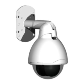
Fig. 1 Parts of the Solaris™ Dome Mounting bracket (fixed horizontally or vertically) Hinged bracket assembly Dome Bubble 1.5" BSP mounting thread Screw for hinge assembly Siemens Building Technologies Fire Safety & Security Products 08.2006... -
Page 15: Installation Of The Dome Unit
(brass cleaner). However, if this is not effective the bubble must be replaced. Siemens Building Technologies Fire Safety & Security Products 08.2006... -
Page 16: Installation Procedure
Route the cable through the Dome bracket. See Section 8.5: Cat5 cable assembly and disassembly. Connect the cable to the Dome unit. See Section 18.6: Connecting the Solaris™ Dome. Attach the Dome to the Dome bracket. Siemens Building Technologies Fire Safety & Security Products 08.2006... -
Page 17: Installing The Mounting Brackets
Bolt the wall/ceiling mount to the mounting substrate using the four mounting holes shown. NOTE Ensure the chosen fasteners and fastening method are suitable for the application and the mounting substrate. Siemens Building Technologies Fire Safety & Security Products 08.2006... -
Page 18: Corner Mount Adapter Ccds1415-Cma
Ensure the chosen fasteners and fastening method are suitable for the application and the mounting substrate. Fig. 6 Wall bracket in conjunction with corner mount adapter Fig. 7 Solaris™ Dome mounted to wall bracket and corner mount adapter Siemens Building Technologies Fire Safety & Security Products 08.2006... -
Page 19: Parapet Mount Adapter Ccds1415-Bm
Ensure the chosen fasteners and fastening method are suitable for the application and the mounting substrate. Fig. 8 Wall bracket in conjunction with parapet mount adapter Fig. 9 Solaris™ Dome mounted to wall bracket and parapet mount adapter Siemens Building Technologies Fire Safety & Security Products 08.2006... -
Page 20: Pendant Mount Ccds1415-Pm
Fasten the mounting flange to the mounting substrate using the three holes shown. NOTE Ensure the chosen fasteners and fastening method are suitable for the application and the mounting substrate. Fig. 10 Pendant mount Siemens Building Technologies Fire Safety & Security Products 08.2006... -
Page 21: Pole Fixture (Using Wall Mount Ccds1415-Wm)
Handle the bubble of the Solaris™ Dome with extreme care and be sure not to scratch it, as this may affect its optical clarity. Fit the ceiling mount accessory brackets in place using the four self-tapping screws provided. Siemens Building Technologies Fire Safety & Security Products 08.2006... - Page 22 The recessed ceiling tile mount is for use with standard thickness ceiling tiles. If using non-standard thickness ceiling tiles, it may be necessary to use different support screws (not supplied) to mount the brace bars onto the accessory brackets. Siemens Building Technologies Fire Safety & Security Products 08.2006...
-
Page 23: Preparing The Dome Bracket
To prepare the bracket for mounting the Dome: Orientate the two parts of the bracket correctly. Siemens Building Technologies Fire Safety & Security Products 08.2006... - Page 24 Screw the locknut onto the bracket, to the back of the thread. Screw the Dome bracket onto the wall mount and position it correctly. A minimum of four turns will be sufficient. Siemens Building Technologies Fire Safety & Security Products 08.2006...
-
Page 25: Cat5 Cable Assembly And Disassembly
Dome unit. The Solaris™ Dome will not be fully water protected if these vital checks are IMPORTANT not made prior to finalising the installation. Label Seal 2 Seal 1 Connector Spring-clip Siemens Building Technologies Fire Safety & Security Products 08.2006... -
Page 26: Assembly
Ensure that the spring-clip securely fastens and locks the connector to the Solaris™ Dome. This will ensure that Solaris™ is waterproof 8.5.1 Assembly Pass the connector locking nut over the RJ45 plug. Siemens Building Technologies Fire Safety & Security Products 08.2006... - Page 27 When fully engaged, the cable will not be able to be retracted from the body when pulled. Fit the plastic washer. Take care not to damage the cable. Fit the rubber washer. Split the compression clamp, orientation as shown. Siemens Building Technologies Fire Safety & Security Products 08.2006...
- Page 28 Finally, loop the cable as shown. Lock the cable in position with the cable tie provided. This ‘loop and tie’ will divert water that runs down the cable away from the connector assembly. Siemens Building Technologies Fire Safety & Security Products 08.2006...
-
Page 29: Disassembly
Using a small tool (screwdriver, pen, etc.) carefully disengage the RJ45 plug from the connector body. Carefully pull the RJ45 plug away from the body by gently pulling on the cable. Siemens Building Technologies Fire Safety & Security Products 08.2006... -
Page 30: Connecting The Solaris™ Dome
Pull the Dome unit into the vertical position (taking care that the cable doesn’t snag) and lock it into place with the fixing screw. The installation of the Dome is now complete. Siemens Building Technologies Fire Safety & Security Products 08.2006... -
Page 31: Installation Of The External Termination Unit (Xtu)
(power, telemetry, alarms etc.) and the Dome. See Section 9.2.1: Choosing a location for the XTU. Select the appropriate cable glands for the cabling/connections to be used and remove the required knockouts in the enclosure. Siemens Building Technologies Fire Safety & Security Products 08.2006... -
Page 32: Choosing A Location For The Xtu
7 x M12/M20 – 2 x M16/M25 – Offer the enclosure up to the mounting holes and fix in place with the chosen fasteners. Siemens Building Technologies Fire Safety & Security Products 08.2006... -
Page 33: Connecting The Xtu To External Equipment
The cable should be a 75 Ohm CCTV cable URM70, RG59, CT125, etc. NOTE The higher the quality of the cable, the further the XTU can be from the controller whilst maintaining good video quality. Siemens Building Technologies Fire Safety & Security Products 08.2006... - Page 34 Use the outputs COM to N/O and/or N/C to control an auxiliary device, such as an alarm system. Warning: 1.5 A, 24 V DC max. 2-core telemetry cable from Photon controller [OPTIONAL] Connect to this terminal if Photon telemetry is to be used (not polarised). Siemens Building Technologies Fire Safety & Security Products 08.2006...
-
Page 35: Xtu Connections - Coaxial (C-Type) Telemetry
Tamper switch From PSU Programming header (do not use) Telemetry indicator Coax cable (video to & telemetry from controller) Dome unit Dome connection cable Camera input / telemetry output Telemetry controller Siemens Building Technologies Fire Safety & Security Products 08.2006... -
Page 36: Xtu Connections - Rs485 (D-Type) Telemetry
Programming head (do not use) Telemetry indicator RS485 telemetry termination link Coax cable (video to controller) Twisted pair telemetry cable Dome unit Dome connection cable Camera input Telemetry controller RS 485 telemetry output Siemens Building Technologies Fire Safety & Security Products 08.2006... -
Page 37: Xtu Connections - Photon Telemetry
Tamper switch From PSU Programming head (do not use) Telemetry indicator Coax cable (video to controller) 2-core telemetry cable Dome unit Dome connection cable Photon telemetry controller Camera input Telemetry output Siemens Building Technologies Fire Safety & Security Products 08.2006... -
Page 38: Wiring Guide
Brown DC 0 V RJ45 plug part reference guide For solid core cable (e.g. Belden 11700A), use AMP5-569278-4 or equivalent. Ensure that a suitable crimping tool is used (e.g. Telemaster 30-496). Siemens Building Technologies Fire Safety & Security Products 08.2006... -
Page 39: Configuration Of The External Termination Unit
2 minutes of inactivity. NOTE Whilst in this mode, pressing the Up or Down keys will alter the brightness of the LCD display. Siemens Building Technologies Fire Safety & Security Products 08.2006... -
Page 40: Lcd Orientation
[Down key] = checked (on) [Up key] = unchecked (off) Software info Displays the software's version details. Factory reset Resets the XTU configuration back to the factory default settings. Test mode Opens the test menu. Siemens Building Technologies Fire Safety & Security Products 08.2006... - Page 41 PHOTON RESTORE XTU->HU TELEMETRY LINE BREAK ACTION PTZF TTY MODE SOFTWARE INFO E2PROM EXIT XTU VERSION FACTORY TEST HU VERSION FACTORY TEST RESULTS EXIT EXIT Fig. 19 The XTU main menu Siemens Building Technologies Fire Safety & Security Products 08.2006...
-
Page 42: Xtu Setup
Select the receiver address (camera number). MAIN XTU MENU >> RECEIVER ADR Press the button to view if the video signal is present. Press the button to exit ‘live video’ mode. Siemens Building Technologies Fire Safety & Security Products 08.2006... -
Page 43: Configuration Of The Dome Unit
Soft Limits will allow you to set up and remove software limits that restrict the SECTORS vertical travel of the camera. Sectors will allow individual identification, by name, of the 16 sectors available within the Solaris™ Dome’s horizontal movement. Siemens Building Technologies Fire Safety & Security Products 08.2006... -
Page 44: The Passcodes Menu
CHANGE INSTALLER CODE PASSCODE MENU CHANGE OPERATOR CODE STORE CHANGE INSTALLER CODE HELP BACK CHANGE OPERATOR CODE ENTER NEW PASSCODE STORE Fig. 20 The PASSCODES menu Siemens Building Technologies Fire Safety & Security Products 08.2006... -
Page 45: The Camera Menu
Backup Dome unit All the Dome settings such as camera setup, presets, tours, patterns, privacy zones and text can be backed up to the XTU and restored at a later date if the Dome is switched with another or replaced. Siemens Building Technologies Fire Safety & Security Products 08.2006... - Page 46 Priority settings are selected. When KEYBOARD is selected, Iris can be manually controlled using the Iris keys on the VK3-keyboard. Turning ON Auto Iris on the keyboard will switch to automatic mode. Siemens Building Technologies Fire Safety & Security Products 08.2006...
-
Page 47: The Presets, Tours And Patterns Menu
A random tour is a tour that consists of the steps used in tour 1, but are replayed in a random order. This helps prevent potential criminals from studying and learning the movement of a traditional tour. Siemens Building Technologies Fire Safety & Security Products... - Page 48 Setting is read only, not editable ALARM 6... (Set 1-99) ALARM 3..(Set 1-99) ‘O’ means no preset assigned ALARM 7 ... (Set 1-99) ALARM 4-7 to Alarm. Fig. 22 The PRESETS, TOURS and PATTERNS menu Siemens Building Technologies Fire Safety & Security Products 08.2006...
-
Page 49: The Privacy Zones Menu
The PRIVACY ZONES menu ) Select Next to view the next stored zone. Select Delete to remove a zone. ) Follow the on-screen instructions to define up to 24 privacy zones. Siemens Building Technologies Fire Safety & Security Products 08.2006... -
Page 50: The Soft Limits And Sectors Menu
) Each sector can have up to 24 characters of text assigned to it. If blank, the whole line is highlighted, press ‘Set’ to add characters. Siemens Building Technologies Fire Safety & Security Products 08.2006... -
Page 51: The Alarm Menu
1). Alternatively, you can select any of the four tours or four patterns (assuming these have been programmed – see Section 11.1.3: The Presets, Tours and Patterns menu). Time period Sets a delay period before performing the action specified in ‘Alarm resume’ Siemens Building Technologies Fire Safety & Security Products 08.2006... - Page 52 Fig. 25 The ALARM menu ) Each alarm can have up to 24 characters of text assigned to it. If blank, the whole line is highlighted, press "Set" to add characters. Siemens Building Technologies Fire Safety & Security Products 08.2006...
-
Page 53: The Osd Menu
) Setting is read only, not editable. ) “CAMERA NAME” can have up to 24 characters of text assigned to it. If blank, the whole line is highlighted, press ‘Set’ to add characters) Siemens Building Technologies Fire Safety & Security Products 08.2006... -
Page 54: The Diagnostics Menu
TILT SPEED XTU TEMP MORE ZOOM POSITION HEATER FOCUS POSITION BACK DISTANCE KM CONTACT DETAILS MORE FAN CONDITION BACK BACK Fig. 27 The DIAGNOSTICS menu ) Setting is read only, not editable. Siemens Building Technologies Fire Safety & Security Products 08.2006... -
Page 55: Telemetry Controller Operation And Setup
Telemetry controller operation and setup This chapter explains how to operate the Solaris™ Dome using a telemetry controller and describes: Accessing the OSD (Siemens, Molynx 6000, V3i and 3rd party) Protocol tables 12.1 Telemetry keyboard operation A great deal of the configuration and set up of the Solaris™ Dome must be carried out using the on-screen menu system that is described in Section 11: Configuration of the Dome unit. -
Page 56: Access To The Osd With Bewator Controllers
10.3: The XTU main menu for details. Navigate the menus using the joystick. To select use Preset 3 Recall. NOTE Use Preset 1 to toggle between Pan / Tilt (camera operation) and OSD menu navigation. Siemens Building Technologies Fire Safety & Security Products 08.2006... -
Page 57: Advanced Camera Functions
Auto Iris 12.3 Use with Siemens controllers The Siemens CCDA protocol is implemented and may be selected from the protocol menu. Controlling the dome using the CCDA protocol can be performed by direct connected keyboard CKA48xx/CKA32xx, SIMATRIX Neo (Port 1) and SIMATRIX SYS / 648 / 164 by using the dome converter CAC0103, Release V1.7... -
Page 58: Direct Control Via Cka48Xx/Cka32Xx
12.3.1 Direct control via CKA48xx/CKA32xx NOTE We recommend following interfacing: RS485 connection, 9600 baud, even parity, 8 data bits, 1 stop bit Camera addressing is 0-127 Tested using Siemens keyboard CKA4820 Operation User Notes keyboard action Pan Left (variable speed) -
Page 59: Control Via Simatrix Neo And Dome Converter Cac0103
Stops recording current pattern. 12.3.2 Control via SIMATRIX NEO and dome converter CAC0103 The Siemens Solaris™ Dome can be controlled via the SIMATRIX video matrices. SIMATRIX NEO provides direct physical connection via telemetry port 1. For connection with SIMATRIX SYS / 648 / 164 an additional dome converter CAC0103, Release V1.7 (Aug. -
Page 60: Use With Bewator Controllers
Up, Down, Left and Right (the joystick can be switched between cursor movement and camera control by Recall [PAUSE] Preset 1). [MULTISCREEN] [REWIND] [FAST FWD] *) The presets used to access the OSD are programmable via the XTU Siemens Building Technologies Fire Safety & Security Products 08.2006... -
Page 61: Pccon, Pccon 1-Way And Pccon Multidrop
Preset range 1-99; speed range 1-100%. Relay Status @26, 1 Return relay status (must be relay 1). 0=open, 1=closed Relay Control @27,1,f Operate relay (f=0 to turn off, f=1 to turn off). Must be relay 1. Siemens Building Technologies Fire Safety & Security Products 08.2006... - Page 62 If the protocol is set to 'PCCON 1-Way' no responses will be returned under any circumstances. If the protocol is set to PCCON multidrop, @3 must be used to select the required camera before any commands will be processed. Siemens Building Technologies Fire Safety & Security Products 08.2006...
-
Page 63: Use With 3Rd Party Controllers
It is possible to configure the Solaris™ Dome to be controlled via RS485 using a number of other manufacturer's controllers. When using a controller other than those offered by Siemens or Bewator (incorporating Molynx technology); there may be variations in the actions a user must take in order to perform a particular task. -
Page 64: Ernitec Erna Protocol
Preset 3 operates as SET. * The presets used to access the OSD are programmable via the XTU. ** It is recommended that the OSD is used to setup a Tour. Siemens Building Technologies Fire Safety & Security Products 08.2006... -
Page 65: Vcl Protocol
[LAMPS] off Lamps off switches camera to day mode (colour/mono version only). One-Touch White Balance [IC] If one-touch white balance is enabled in OSD and exposure priority is not set to KEYBOARD. Siemens Building Technologies Fire Safety & Security Products 08.2006... -
Page 66: Photon Protocol
Deactivates Auxiliary 3 function. Switches camera to day mode (external version only). One-Touch White Balance [Iris Close] If one-touch white balance is enabled in OSD and exposure priority is not set to KEYBOARD. Siemens Building Technologies Fire Safety & Security Products 08.2006... -
Page 67: Philips Protocol
When in OSD cursor mode Recall camera control.[3] [SHOT] for Set. Preset 3 operates as SET. * The presets used to access the OSD are programmable via the XTU. Siemens Building Technologies Fire Safety & Security Products 08.2006... -
Page 68: Maintenance
Remove the Dome fixing screw. Fixing Screw Hold the Dome unit around its main body and swing it into the horizontal position. Disengage the connectors locking clip. Disconnect the connector from the socket. Siemens Building Technologies Fire Safety & Security Products 08.2006... -
Page 69: Monthly Checks
(available from electronics suppliers, e.g. RS). Small scratches or scuffs can be removed from the outer surface with the use of a suitable cloth and metal polish (brass cleaner). Siemens Building Technologies Fire Safety & Security Products 08.2006... -
Page 70: Disposal
It is a precondition for reuse and recycling of used electrical and electronic equipment. For more detailed information about disposal of your old appliance, please contact your city office, waste disposal service or the shop where you purchased the product. Siemens Building Technologies Fire Safety & Security Products 08.2006... -
Page 71: Keyword Index
Pendant mount CCDS1415-PM 20 Bewator controller 56, 60 Pole fixture (using wall mount CCDS1415-WM) CKA4820/CKA3210 55 CKA48xx/CKA32xx 58 Preparing the Dome bracket 23 Siemens controller 57 Procedure 16 SIMATRIX NEO 55 Recessed ceiling tile mount CCDS1415-FM 21 SIMATRIX SYS/648/164 55 Tools required 15... - Page 72 Videmech Universal protocol 65 Main menu 15, 40, 45, 56 Setup 42 XTU connections Safety 6 Coaxial (C-type) telemetry 31, 33, 35 Safety precautions 6 Photon telemetry 37 Sandards 9 RS485 (D-type) telemetry 36 Siemens Building Technologies Fire Safety & Security Products 08.2006...
- Page 74 Issued by © 2006 Copyright by Siemens Building Technologies Siemens Building Technologies AG Fire & Security Products GmbH & Co. oHG Data and design subject to change without notice. D-76181 Karlsruhe Supply subject to availability. Printed in the Federal Republic of Germany www.sbt.siemens.com...