Table of Contents
Advertisement
Advertisement
Table of Contents

Related Manuals for Electrolux Compact


Summary of Contents for Electrolux Compact
- Page 1 SERVICE MANUAL DISHWASHER COMPACT Dishwasher COMPACT 911 328 ..© AEG Hausgeräte GmbH Publ.-Nr.: Muggenhofer Straße 135 599 516 219 D-90429 Nürnberg Germany Fax +49 (0)911 323 1022 Spares Operation Edition: 01.03 - 1 - Spares Operation - R.Kurzke 02/03...
-
Page 2: Table Of Contents
Index Technical specifications ..................3 Installation water drainage ..................3 Components ......................4 Capacitor ....................... 4 Pressure switch ..................... 4 Heater element ...................... 4 Circulation pump ....................5 Drain pump ......................5 NTC temperature sensor ..................5 Programmer ......................5 Detergent dispenser .................... -
Page 3: Technical Specifications
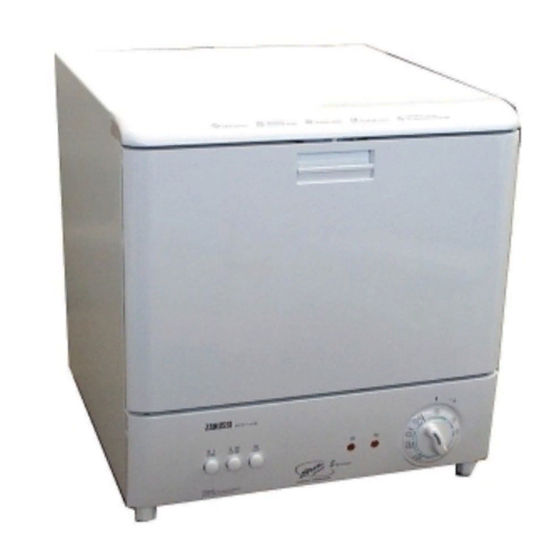
On/Off-button Programme selector Temperature selector Indicator lamp Extra drying effect Salt indicator lamp Technical specifications Power supply: 230 V - 50 Hz Heater element: 1200 W Power rating: 1280 W Fuse required: 13 A Height: 460 mm Width: 450 mm Depth: 480 mm Water pressures:... -
Page 4: Components
3. Components Capacitor The circulation pump is connected to a capacitor. 2,0 µF for UK 2,5 µF for Europe Pressure Switch The pressure switch controls the water level. Without water, contact is closed. Adjusting: Turning the marked screw clockwise level Turning the marked screw anti clockwise level Heating element... -
Page 5: Circulation Pump
Circulation Pump The circulation pump is driven by an asynchronous motor with an starting winding. The starting winding ist in circuit with a 2,5 µF (Euro) capacitor. (2 µF UK) Rating: 60/80 W Main winding resistance 158 Ohm Starting winding resistance 158 Ohm Drain Pump The drain pump is driven by a synchronous motor. -
Page 6: Detergent Dispenser
Detergent dispenser Coil resistance 3000 Ohm Rinse aid dispenser Rinse agency capacity 140 ccm Solenoid coil resistance 1900 Ohm Inlet valve Capacity, max, 4 l/min Resistance 4800 Ohm Anti flood switch If the anti flood swich in the base tray is activated, all components are switched off except the drain pump - 6 - Spares Operation - R.Kurzke 02/03... -
Page 7: Water Softening System
Water softening system Operation of the water softening system When water is admitted, the inlet valve (1) opens and the hard water flows down into the ion exchanger (5), through which it flows and is softened before flowing through the water inlet (6) and then being sprayed into the Washing chamber. -
Page 8: Position Of Components
4. Position of components Door opener Inner door Outer door Door seal Programmer / Timer Signal lamps Switches (temperature) - 8 - Spares Operation - R.Kurzke 02/03 599 516 219 EN... - Page 9 Housing Coil for detergent dispenser Rinse-aid dispenser Door switch Basek rails Coarse sieve Interference filter Fine strainer Heating element Thermostats Base plate - 9 - Spares Operation - R.Kurzke 02/03 599 516 219 EN...
- Page 10 Softener Inlet hose Drain hose anti-siphon valve Regeneration valve Reed switch Inlet valve salt indicator Float switch Pressure switch Drain pump Water collector Base plate Circulation pump Air chamber - 10 - Spares Operation - R.Kurzke 02/03 599 516 219 EN...
- Page 11 Spray arm Sealing ring Pump housing Cup support Cuttlery basket Dish rack Basket roller - 11 - Spares Operation - R.Kurzke 02/03 599 516 219 EN...
-
Page 12: Water Course Scheme
Water Course Scheme - 12 - Spares Operation - R.Kurzke 02/03 599 516 219 EN... -
Page 13: Water Inlet
Water Inlet The water flows into the regeneration dosage chamber via inlet valve, over air break, into regeneration dosage chambers and into softener The level control container operates the pressure switch. - 13 - Spares Operation - R.Kurzke 02/03 599 516 219 EN... -
Page 14: Rinsing System
Rinsing system The function of the rinsing system is to wet the dishes loaded into the machine. The electric motor of the circulation pump is delivered with the impeller fitted to it. Half the pump casing forms part of the plastic chassis, CERAMIC NUT and the other half is bolted in position inside the SPRAY TUBE... -
Page 15: Strainer System
Strainer system The strainer system is one of the systems which are most important to the performance of the dishwasher. The design of this system is largely decisive to whether the dishwasher will be able to perform its most fundamental task: to wash the dishes clean. The strainer system must trap particles of food, etc. -
Page 16: Level Control System
Europe), the time allowed will be too short to fill the machine with a sufficient amount of water. A time-controlled machine needs a water pressure of at least 1.0 - 1.5 kg/cm2. The Compact dishwasher is level-controlled and will perform satisfactorily at mains water pressures down to 0,5 kg/ cm². -
Page 17: Inlet System / Overfilling/Leakage Protection (Old Version)
Old version Inlet system - old version The inlet hose is a rubber hose with plastic cover. The coupling nuts are made of plastic (which reduces the risk of crossedhreads) . The inlet hose is inside the washing chamber when the machine is delivered, and the consumer must fit the hose when installing the machine. -
Page 18: Drain System
10. Drain system The system consists of inner and outer drain hoses and a drain pump, and its function is to transport the contaminated water as efficiently as pos-sible from the machine to the waste water system of the buildin The drain pump is connected to the chassis at the coarse strainer and is sealed with an O-ring. -
Page 19: Regeneration
11. Regeneration The water chamber for regeneration contains 350 ml water. During regeneration, the regeneration valve is energized. The 350 ml water runs into the salt container and mixes with the salt to form a brine solution. In the top of the salt container there is an opening with a small filter, from here the brine solution enters the softener where the resins are regenerated. -
Page 20: Thermostats
12. Thermostats The thermostats are pressed into the tubular mountings in the plastic chassis. They measure the temperature on the outside of the plastic wall, which leads to a certain difference between the water temperature thermostat temperature. However, the specifications of the thermostats take this into account. -
Page 21: Temperatur And Safety Systems
13. Temperature control and safety Systems The dishwashing detergents available on the market today require a certain water temperature before they can dissolve the food residues in a satisfactory way. A temperature control system consisting of a heater element and thermostats ensures that the water will be heated to the correct temperature. -
Page 22: Wirings And Diagrams
14. Wirings (Example DSC 14) - 22 - Spares Operation - R.Kurzke 02/03 599 516 219 EN... - Page 23 Diagram (Example DSC 14) - 23 - Spares Operation - R.Kurzke 02/03 599 516 219 EN...
- Page 24 Wirings (Example DSC 382) - 24 - Spares Operation - R.Kurzke 02/03 599 516 219 EN...
- Page 25 Diagram (Example DSC 382) - 25 - Spares Operation - R.Kurzke 02/03 599 516 219 EN...
-
Page 26: Service Informations
15. Service Informations Coarse filter The purpose of the coarse filter is to catch large objects. Make sure that the filter is always clean. Fine filter It is just important to keep this filter clean. The fine filter can easily be lifted out for cleaning when the coarse filter is removed at first. -
Page 27: Housing
You need screwdriver Torx TX20 Housing After removing the housing screws (lay the machine on its side) from the bottom of the machine, the housing is unclipped front and back from the catches and can be removed. All components from the left and right side are now accessible. Rinse-aid dispenser Coil for Softener... -
Page 28: Panel / Base Plate
Replacement of the panel Remove the screws from the panel frame. Remove the turning knob. Carefully unclip the front . Before finally opening, unclip the lamps. Remove the base plate The base plate of the machine is held with screws on the lower panel and at the bottom. - Page 29 Switches Programmer / Timer (temperature) Thermostats Drain pump Air chamber Interference filter Circulation pump Float switch Regeneration valve Softener Inlet valve Heating element - 29 - Spares Operation - R.Kurzke 02/03 599 516 219 EN...
-
Page 30: Door Components
Outer and inner door They snap together and are held by plastic latches, on the under side. They can easily be unsnapped Replacement of the components within the door. After removing these screws, door handle detergend dispenser flap can be removed from the inner door. -
Page 31: Door Switch
To remove the inner door Remove the lower panel and the outer door. Open the door and remove the four screws (two on each side) securing the rack rails. Open the door to an angle of about 130° and carefuly relese the hinge pin on the right hand side. On the left hand side, the hinge pin is inserted in a hole without slot. -
Page 32: Rinse Aid Dispenser / Detergent Dispenser Coil
Remove this screw to dismount the rinse aid dispenser unit The coil with tappet as support for the detergent dispenser is held by two screws. - 32 - Spares Operation - R.Kurzke 02/03 599 516 219 EN... -
Page 33: Pressure Switch / Anti-Siphon Valve / Level Control Container
The pressure monitor is simply screwed. The motor capacitor is screwed by a nut. Anti-siphon valve The air should be able to enter the hose from the Level control holder - not the other way around! container The take-off hose ventilation can be unscrewed (Air chamber) for cleaning when necessary, in case these rubber parts in the interior of this... -
Page 34: Thermostats / Heater Element
Thermostats The mounting for the thermostats is screwed at the right side of the air chamber. After its release, the thermostats can be removed. Heater element After the removal of the nut and the heater clip in the sump under the fine strainer, the heater element can be drawn forward through the chassis opening to remove.. -
Page 35: Programmer / Switch Unit / Float Switch / Inlet Valve
Programmer The programmer is secured to the front of the chassis by means of two screws. Remove the programmer from the right side of the chassis. Switch unit The switch unit is secured by means of screws and easily to remove. -
Page 36: Circulation Pump / Drain Pump
Circulation pump After loosening the screws of the holder, the circulation pump can be taken out of the pump chamber. Drain pump To dismount the drain pump, the hose clamps are released and the screws removed. After removing the drain pump Here you can see how the hose clamps can be re-tensioned with the tubing-bow with seals,... -
Page 37: Softener / Regeneration Valve
Softener 1 To dismount the water softener, these attachment screws are removed. 2 The connections on the reed switch are removed. 3 The hose connections are detached. 4 The large nut of the salt hol der must be released . 5 A spanner is useful in removing the recycling inlet nut. -
Page 38: Leakage Points
Leakages. Service solutions: Take of the cover to be able to see the Container on the left hand side. Let the dishwasher take in water and check the level. If the level is too high (leakage through the top of the Container) adjust the pressure level switch check assembling ofthe Container to tub, misaligned oring or screw not tightened. - Page 39 Check the locknut under the salt cap to ensure it is fully tightened. It should not be possible to unsrew by hand. In the case of leakage, here more checkpoints - 39 - Spares Operation - R.Kurzke 02/03 599 516 219 EN...
-
Page 40: Fault Tracing
- 40 - Spares Operation - R.Kurzke 02/03 599 516 219 EN... - Page 41 - 41 - Spares Operation - R.Kurzke 02/03 599 516 219 EN...
- Page 42 - 42 - Spares Operation - R.Kurzke 02/03 599 516 219 EN...