Fujitsu PRIMERGY RX200 S6 Operating Manual
Hide thumbs
Also See for PRIMERGY RX200 S6:
- Options manual (84 pages) ,
- Service supplement manual (50 pages)
Table of Contents
Advertisement
Advertisement
Table of Contents

Related Manuals for Fujitsu PRIMERGY RX200 S6


Summary of Contents for Fujitsu PRIMERGY RX200 S6
- Page 1 Operating Manual - English PRIMERGY RX200 S6 Operating Manual April 2010...
-
Page 2: Copyright And Trademarks
– The contents of this manual may be revised without prior notice. – Fujitsu assumes no liability for damages to third party copyrights or other rights arising from the use of any information in this manual. – No part of this manual may be reproduced in any form without the prior written permission of Fujitsu. - Page 3 Before reading this manual For your safety This manual contains important information for safely and correctly using this product. Carefully read the manual before using this product. Pay particular attention to the accompanying manual "Safety notes and other important information" and ensure these safety notes are understood before using the product.
- Page 4 (hereafter, "high safety use"). Customers should not use this product for high safety use unless measures are in place for ensuring the level of safety demanded of such use. Please consult the sales staff of Fujitsu if intending to use this product for high safety use.
- Page 5 Only for the Japanese market: Although described in this manual, some sections do not apply to the Japanese market. These options and routines include: – USB Flash Module (UFM) – CSS (Customer Self Service) – Replacing the lithium battery Operating Manual RX200 S6...
- Page 6 Operating Manual RX200 S6...
-
Page 7: Table Of Contents
Contents Preface ......11 Concept and target groups for this manual ..11 Documentation overview . - Page 8 Contents Starting up and operation ....61 Controls and indicators ..... 61 5.1.1 Front of server .
- Page 9 Contents Hot-plug components ..... 88 8.1.1 Hot-plug power supply units ....88 8.1.1.1 Remove the dummy module .
- Page 10 Contents Operating Manual RX200 S6...
-
Page 11: Preface
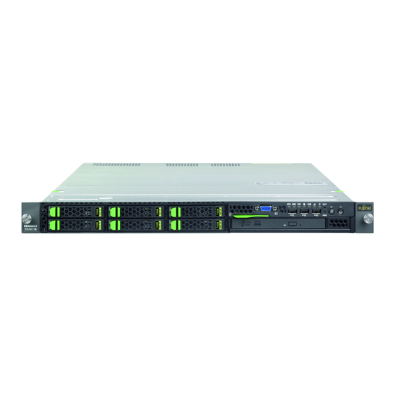
Preface The PRIMERGY RX200 S6 rack server is a universal and high-performance platform designed for a whole range of application areas in data center and server farm concepts. The ultra-compact rack server is ideal for web services and solutions such as caching, gateway and firewall applications. Other application areas include front-end solutions (tier 1) in modern multi-tier configurations, and e-mail service and appliance solutions. -
Page 12: Documentation Overview
Preface Documentation overview More information on your PRIMERGY RX200 S6 can be found in the following documents: – "Quick Start Hardware - PRIMERGY RX200 S6" leaflet " はじめにお読みください -PRIMERGY RX200 S6" for the Japanese market (only included as a printed copy) –... - Page 13 Internet. The overview page showing the online documentation available on the Internet can be found using the URL (for EMEA market): http://manuals.ts.fujitsu.com. The PRIMERGY server documentation can be accessed using the Industry standard servers navigation option. For the Japanese market please use the URL: http://primeserver.fujitsu.com/primergy/manual.html.
-
Page 14: Features
ServerView Suite DVD 2). In addition, CSS errors are displayed in the ServerView Operations Manager, the server management software from Fujitsu. In the event of errors, the ServerView Operations Manager refers you directly to the affected component and its order information in the Illustrated Spares catalog of the server in question. - Page 15 Preface System board The features of the system board are described in the technical manual for the system board D3031 for the hardware and in the BIOS Setup manual for the firmware. Trusted Platform Module (TPM) A Trusted Platform Module (TPM) for safer storage of keys can be implemented as an option.
- Page 16 Preface Hard disk drives The server can be equipped with a maximum of 6 (variant with DVD slot) or 8 HDD modules. Each HDD module can accommodate an SAS/SATA hard disk drive or an SATA SSD drive with a maximum height of 1 inch. The module is connected to the SAS/SATA backplane wirelessly.
- Page 17 Preface SAS/SATA RAID controller The server is available with the following SAS/SATA RAID controllers for operating the internal SAS/SATA hard disk drives: – Modular RAID 0/1 controller with "Integrated Mirroring Enhanced" (SAS IME) for SAS1.0 RAID levels 0, 1 and 1E are supported for internal hard disk drive configurations.
- Page 18 "hides" the defective system components. The PDA (Prefailure Detection and Analysis) technology from Fujitsu analyzes and monitors all components that are critical for system reliability. A RAID controller supports different RAID levels and increase the availability and data security of the system.
- Page 19 Preface iRMC S2 with integrated management LAN connector The features of the iRMC S2 Advanced Video Redirection and Remote Storage are available as an option. The iRMC S2 (integrated Remote Management Controller) is a BMC with integrated management LAN connector and expanded functionality that was previously only available with additional plug-in cards.
- Page 20 Server management is implemented using the ServerView Operations Manager supplied and the PDA (Prefailure Detection and Analysis) technology from Fujitsu. PDA reports the threat of a system error or overload at an early stage, allowing preventive measures to be taken.
- Page 21 BIOS update. With the iRMC S2 (integrated Remote Management Controller) on the system board, the PRIMERGY RX200 S6 server can also be maintained and serviced remotely. This enables remote diagnosis for system analysis, remote configuration and remote restart should the operating system or hardware fail.
-
Page 22: Notational Conventions
Preface The administrator can access all system information and information from the sensors such as fan speeds or voltages via the iRMC S2's Web interface (see section "iRMC S2 with integrated management LAN connector" on page 19). You can also start the text-based or graphic console bypass (Advanced Video Redirection, AVR) and connect virtual drives as remote storage. -
Page 23: Technical Data
Preface Technical data Electrical data (hot-plug power supply unit) 100 V - 127 V ⁄ 200 V - 240 V Rated voltage range Frequency 50 Hz - 60 Hz Max. rated current (770W PSU) 100 V - 240 V / 10 A - 5 A Max. - Page 24 Preface Compliance with regulations and standards Product safety IEC 60950-1/2, EN 60950-1/2, UL/CSA 60950-1/2, CNS 14336, GB 4943, EN 50371 Ergonomics ITK1 ITB2003:2007 Electromagnetic FCC class A compatibility CNS 13438 class A; VCCI class A AS/NZS CISPR 22 class A / GB 9254 class A GB 17625 interference EN 55022 class A...
- Page 25 Preface Dimensions / Weight Rack (W x D x H) 482.6 mm (bezel) / 431mm (body) x 765 x 43 mm (1U) Mounting depth rack 728 mm Height unit rack 19" rackmount Mounting cable 100 mm (1000 mm rack recommended) depth rack Weight 18 kg...
- Page 26 Preface Noise level Sound power level L (ISO 9296) < 7.0 B (standby) < 7.1 B (operation) Sound pressure level at adjacent workstation < 52 dB (A) (standby) (ISO 9296) < 53 dB (A) (operation) Operating Manual RX200 S6...
-
Page 27: Installation Steps, Overview
Installation steps, overview This chapter contains an overview of the steps necessary to install your server. Links take you to sections where you can find more detailed information about the respective steps: Ê First of all, it is essential that you familiarize yourself with the safety information in chapter "Important information"... - Page 28 Installation steps, overview Ê Configure the server and install the desired operating system and applications. The following options are available: – Remote installation with the ServerView Installation Manager: With the ServerView Suite DVD 1 provided, you can configure the server and install the operating system in a convenient manner.
-
Page 29: Important Information
Important information In this chapter you will find essential information regarding safety when working on your server. Safety instructions The following safety instructions are also provided in the manual "Safety notes and other important information". This device meets the relevant safety regulations for IT equipment. If you have any questions about whether you can install the server in the intended environment, please contact your sales outlet or our customer service team. - Page 30 Important information Before starting up CAUTION! During installation and before operating the device, observe the instructions on environmental conditions for your device (see section "Technical data" on page 23). If the server has been moved from a cold environment, condensation may form both inside and on the outside of the machine.
- Page 31 Important information CAUTION! Ensure that the power sockets on the device and the properly grounded power outlets are freely accessible. The On/Off button or the main power switch (if present) does not isolate the device from the mains power supply. To disconnect it completely from the mains power supply, unplug all network power plugs from the properly grounded power outlets.
- Page 32 Important information CAUTION! Proper operation of the system (in accordance with IEC 60950-1/2 resp. EN 60950-1/2) is only ensured if the casing is completely assembled and the rear covers for the installation slots have been fitted (electric shock, cooling, fire protection, interference suppression).
- Page 33 Important information CAUTION! Install the screw removed during installation/detaching Internal Options in former device/position. To use a screw of the different kind causes a breakdown of equipment. The installation indicated on this note is sometimes changed to the kind of possible options without notice. Batteries CAUTION! Incorrect replacement of batteries may lead to a risk of explosion.
- Page 34 Important information Working with CDs/DVDs/BDs and optical drives When working with devices with optical drives, these instructions must be followed. CAUTION! Only use CDs/DVDs/BDs that are in perfect condition, in order to prevent data loss, equipment damage and injury. Check each CD/DVD/BD for damage, cracks, breakages etc. before inserting it in the drive.
- Page 35 Important information Do not contaminate the CD/DVD/BD surface with fingerprints, oil, dust, etc. If dirty, clean with a soft, dry cloth, wiping from the center to the edge. Do not use benzene, thinners, water, record sprays, antistatic agents, or silicone-impregnated cloth. Be careful not to damage the CD/DVD/BD surface.
- Page 36 Important information Modules with Electrostatic-Sensitive Devices Modules with electrostatic-sensitive devices are identified by the following sticker: Figure 1: ESD label When you handle components fitted with ESDs, you must always observe the following points: Switch off the system and remove the power plugs from the power outlets before installing or removing components with ESDs.
-
Page 37: Energy Star
Important information Other important information: During cleaning, observe the instructions in section "Cleaning the server" on page Keep this operating manual and the other documentation (such as the technical manual, documentation DVD) close to the device. All documentation must be included if the equipment is passed on to a third party. -
Page 38: Ce Conformity
Important information CE conformity The system complies with the requirements of the EC directives 2004/108/EC regarding "Electromagnetic Compatibility" and 2006/95/EC "Low Voltage Directive". This is indicated by the CE marking (CE = Communauté Européenne). Transporting the server CAUTION! Only transport the server in its original packaging or in packaging that protects it from impacts and jolts. -
Page 39: Notes On Installing The Server In The Rack
Important information Notes on installing the server in the rack CAUTION! For safety reasons, at least two people are required to install the server in the rack because of its weight and size. (For the Japanese market, please refer to " 安全上の注意およびその 他の重要情報... -
Page 40: Environmental Protection
Important information Environmental protection Environmentally-friendly product design and development This product has been designed in accordance with the Fujitsu standard for "environmentally friendly product design and development". This means that key factors such as durability, selection and labeling of materials, emissions, packaging, ease of dismantling and recycling have been taken into account. - Page 41 Details regarding the return and recycling of devices and consumables within Europe can also be found in the "Returning used devices" manual, via your local Fujitsu branch or from our recycling center in Paderborn: Fujitsu Technology Solutions Recycling Center D-33106 Paderborn Tel.
- Page 42 Important information Operating Manual RX200 S6...
-
Page 43: Hardware Installation
Hardware installation CAUTION! Follow the safety instructions in the chapter "Important information" on page Do not expose the server to extreme environmental conditions (see "Ambient conditions" on page 25). Protect the server from dust, humidity and heat. Make sure that the server is acclimatized for the time indicated in this table before putting it into operation. -
Page 44: Unpacking The Server
Hardware installation Unpacking the server CAUTION! Follow the safety instructions in chapter "Important information" on page The server must always be lifted or carried by at least two people. (For the Japanese market, please refer to " 安全上の注意およびその他の 重要情報 ".) Do not unpack the server until it is at its installation location. -
Page 45: Installing/Removing The Server In/From The Rack
4.2.1 Rack system requirements The rack systems from Fujitsu PRIMECENTER Rack, DataCenter Rack and 19-inch standard rack (for the Japanese market) support the installation of PRIMERGY servers. Installation in most current rack systems from other manufacturers (3rd party racks) is also supported. - Page 46 Hardware installation PRIMECENTER Rack and DataCenter Rack provide an enhanced cable management in the lateral rack area. For PRIMECENTER Racks and DataCenter Racks: The mounting of the rails in the different racks is described in the next sections. Installation of the cable management is described in detail in the Technical Manual for the respective rack.
- Page 47 Hardware installation +/- 1,6mm Figure 2: Mechanical requirements Operating Manual RX200 S6...
-
Page 48: Installation In Primecenter/Datacenter Rack
Hardware installation – You must ensure that the safety mechanisms on the server, e.g. stoppers or retaining systems, are functioning correctly. – The shape of the rack support uprights must ensure that the support systems can be bolted to the front. The support systems have a linear alignment feature to ensure that they can be adjusted to different rack depths. - Page 49 Hardware installation Fitting the support bracket When mounting the left support system in the corresponding rack, the supplied support bracket must first be mounted flush with the underside of the device on the rear left support upright. Figure 3: Fitting the support bracket Ê...
- Page 50 Hardware installation Removing the outer telescopic rail Figure 4: Removing the outer telescopic rail Ê Extend the telescopic rail fully (1). Ê Unlock the outer telescopic rail and remove it. With fully-extendable rails (a): Press the locking lever to release the server rail.
- Page 51 Hardware installation Installing the support systems Figure 5: Fit the left support system in the PRIMECENTER/DataCenter rack Ê Position the left support system in the support bracket (insert retaining bolts) - see (1). Ê Clamp the left-hand support system (2) between the front left support upright and the support bracket by pressing the support system together, positioning it on the front support upright and releasing it again.
- Page 52 Hardware installation Ê Insert (3) the safety lock into the easy lock (snap fit). CAUTION! Ensure that the safety lock has been inserted before the server is inserted! Ê Repeat the above steps for the right-hand support system (with the front and rear right support uprights).
- Page 53 Hardware installation Inserting the server For the Japanese market: Refer to "はじめにお読みください" for more detailed explanation and for other support systems. Figure 7: Inserting the server CAUTION! Ensure that the safety lock has been inserted before the server is inserted (see figure 5 on page 51).
-
Page 54: Installation In 3Rd Party Racks
4.2.3 Installation in 3rd party racks The support systems from Fujitsu are suitable for use in any 3rd party racks for standard servers (installation depth 714 - 785 mm) without restrictions. Ê Refer to the manual from the rack manufacturer for details of the mechanical installation and the climatic conditions. - Page 55 Hardware installation Racks with installation depth smaller/greater than 735 mm The support systems can be used for installation depths of 714 - 785 mm. The spring element of the support system is used to adjust the length as required. Ê Secure the support systems as described in section "Installing the support systems"...
-
Page 56: Connecting Devices To The Server
Hardware installation Connecting devices to the server The connectors for external devices are on the front and rear of the server. The additional connectors available on your server depend on the expansion cards installed. For further information refer to the “Options Guide”. The standard connectors are marked with symbols, and some are color-coded: Figure 8: Connection panel on the rear 1 USB connectors... - Page 57 Hardware installation One video connector (1) and three additional USB connectors (2) are located on the front of the server (figure Figure 9: Connectors on the front Connecting the keyboard, mouse and monitor Ê Connect the keyboard and mouse to the USB connectors of the server. Ê...
-
Page 58: Connecting The Server To The Mains
Hardware installation Connecting the server to the mains In its basic configuration level the server has a hot-plug power supply unit. A second hot-plug power supply unit can be added to ensure a redundant power supply. If one power supply unit is defective, the other then guarantees unimpaired operation. -
Page 59: Using The Cable Clamp
Hardware installation 4.4.1 Using the cable clamp You can secure the power cords in a cable clamp to ensure that the insulated connectors cannot be disconnected from the server accidentally. Figure 11: Cable clamp Ê Pull the cable clamp up (1). Ê... -
Page 60: Notes On Connecting/Disconnecting Cables
Hardware installation Notes on connecting/disconnecting cables CAUTION! Always read the documentation supplied with the device you wish to connect. Never connect, or disconnect cables during a thunderstorm. Never pull on a cable when disconnecting it. Always take hold of the cable by the plug. -
Page 61: Starting Up And Operation
Starting up and operation CAUTION! Please note the safety instructions in chapter "Important information" on page Controls and indicators 5.1.1 Front of server Figure 12: Controls and indicators on the front 1 CPU error indicator 9 ID indicator 2 Memory error indicator 10 Power-on indicator 3 PCI error indicator 11 On/Off button... - Page 62 Starting up and operation Controls On/Off button When the system is switched off, it can be switched on again by pressing the On/Off button. When the system is operating, the result of pressing the On/Off button depends on the operating system configuration (performing a graceful shutdown, going into a sleep state/hibernation, do nothing).
- Page 63 Starting up and operation Indicators on the control panel Power-on indicator (three colors) Lights orange when the server is switched off but mains voltage is present. Lights up yellow during power up delay. If the server is switched off and then immediately switched on again, a server is only restarted after a power up delay.
- Page 64 Starting up and operation CSS indicator (yellow) – Lights up yellow if a prefailure event was detected for a CSS component that you can fix yourself (for reasons of precaution) with the CSS concept. – Flashes yellow if an error was detected that you can fix yourself with the CSS concept.
- Page 65 Starting up and operation Hard disk drive indicators Figure 13: Indicators on the 2.5-inch HDD module HDD BUSY (green) – Lights up: HDD in active phase – Does not light: HDD inactive (drive inactive) HDD FAULT (orange) (in conjunction with a RAID controller) –...
-
Page 66: Rear Of Server
Starting up and operation 5.1.2 Rear of server CSS, Global Error and ID indicators Figure 14: ID/CSS/Global Error indicator 1 Global Error/CSS/ID indicator Global Error indicator (orange) – Lights up orange if a prefailure event has been detected that requires (precautionary) service intervention. –... - Page 67 Starting up and operation CSS indicator (yellow) – Lights up yellow if a prefailure event was detected for a CSS component that you can fix yourself (for reasons of precaution) with the CSS concept. – Flashes yellow if an error was detected that you can fix yourself with the CSS concept.
- Page 68 Starting up and operation LAN indicators Figure 15: LAN indicators No Indicator Description Steady green signal when a LAN connection exists. link/transfer Remains dark when no LAN connection exists. (management LAN) Flashes green when LAN transfer takes place. LAN speed Steady green signal in the event of a LAN transfer rate (management of 100 Mbit/s.
- Page 69 Starting up and operation Indicator on hot-plug power supply unit Figure 16: Indicator on hot-plug power supply unit Indicator on hot-plug power supply unit (two colors) 770 W power supply unit: Flashes green when the server is switched off, but mains voltage is present (standby mode).
-
Page 70: Indicators Of The Hot-Plug System Fans
Starting up and operation 5.1.3 Indicators of the hot-plug system fans A fan status indicator (LED on the system board) is assigned to each system fan. The status indicators are not visible unless the housing is open. The respective LED is set with commands in Server Management. Meaning lights green Fan is operational. -
Page 71: Switching The Server On And Off
Precautions".When operating the device outside of this operating environment, the server may operate improperly, damage data etc.Furthermore, Fujitsu cannot be held responsible for any related damage,malfunction, or loss of data, etc. Be sure to wait for 10 seconds or more after shutdown before turning the server on. - Page 72 Starting up and operation – System already installed: Ê Press the On/Off button (item 5 in figure 12 on page 61). Power-on indicator (item 6 in figure 12 on page 61) lights green. The server is switched on, performs a system test and boots the operating system.
- Page 73 Starting up and operation – Power button override The system can be switched off (hard power off) by holding down the On/Off button (approximately 4 - 5 seconds). CAUTION! There is a risk that data may be lost. – iRMC S2 iRMC S2 offers various options for switching the server on and off, e.g.
-
Page 74: Configuring The Server
Starting up and operation Configuring the server This section contains information about configuring the server and installing the operating system. Make sure that the power saving functions are disabled in the Power menu of the BIOS Setup during operation. 5.3.1 Configuring the onboard SATA controller A SATA controller is integrated on the system board. -
Page 75: Configuring The Server And Installing The Operating System With The Serverview Installation Manager
Starting up and operation Further information on modular RAID controllers is provided in the "Modular RAID Controller Installation Guide" (on the ServerView Suite DVD 2 under Industry Standard Servers - Expansion Cards - Storage Adapters - LSI RAID / SCSI Controllers). Descriptions of operating systems not covered in the controller manual are provided in the corresponding readme files on the driver CDs. -
Page 76: Configuring The Server And Installing The Operating System Without Serverview Installation Manager
Starting up and operation 5.3.4 Configuring the server and installing the operating system without ServerView Installation Manager Configuring the onboard SATA controller Configure the controller as described in section "Configuring the onboard SATA controller" on page Configure SAS/SATA RAID controller with "Integrated Mirroring Enhanced"... -
Page 77: Cleaning The Server
Starting up and operation Cleaning the server CAUTION! Switch the server off and disconnect the power plugs from the properly grounded power outlets. Do not clean any interior parts yourself; leave this job to a service technician. Do not use any cleaning agents that contain abrasives or may corrode plastic. - Page 78 Starting up and operation Operating Manual RX200 S6...
-
Page 79: Property And Data Protection
Property and data protection The lockable rack door protects the server against unauthorized access. To protect your system and data internally against unauthorized access, you can use the BIOS Setup security functions. BIOS Setup security functions The Security menu in BIOS Setup offers various options for protecting your data from unauthorized access. - Page 80 Property and data protection Operating Manual RX200 S6...
-
Page 81: Troubleshooting And Tips
Troubleshooting and tips CAUTION! Follow the safety instructions in the "Safety notes and other important information" manual and in chapter "Important information" on page If a fault occurs, attempt to resolve it using the measures described: – in this chapter, –... -
Page 82: Server Switches Itself Off
Troubleshooting and tips Server switches itself off Server Management has detected an error Ê Check the error list of System Event Log in ServerView Operations Manager or in the iRMC S2 web interface, and attempt to eliminate the error. Screen remains blank Monitor is switched off Ê... -
Page 83: Flickering Stripes On Monitor Screen
Troubleshooting and tips Flickering stripes on monitor screen CAUTION! Switch off the server immediately. Risk of damaging the server. Monitor does not support the set horizontal frequency Ê Find out which horizontal frequency your monitor screen supports. You will find the horizontal frequency (also known as line frequency or horizontal deflection frequency) in the documentation for your monitor. -
Page 84: Incorrect Date And Time
Troubleshooting and tips Incorrect date and time Ê Set the date and time in the operating system or in the BIOS Setup under the Main menu, using System Date and System Time respectively. Note that the operating system may affect the system time. For example, the operating system time may deviate from the system time under Linux, and would overwrite the system time in the default setting on shutdown. -
Page 85: Added Drive Reported As Defective
Troubleshooting and tips Added drive reported as defective RAID controller is not configured for this drive The drive was probably installed when the system was switched off. Ê Reconfigure the RAID controller for the drive using the corresponding utility. Information is provided in the documentation for the RAID controller. Ê... - Page 86 Troubleshooting and tips Operating Manual RX200 S6...
-
Page 87: Css Components
Suite Local Service Concept - LSC" manual on the ServerView Suite DVD 2. For the latest information on optional products provided for the RX200 S6 see the configurator of the server: http://ts.fujitsu.com/products/standard_servers/index.html (for the EMEA market) http://primeserver.fujitsu.com/primergy/system.html (for the Japanese market) CAUTION! Do not disassemble the power supply unit. -
Page 88: Hot-Plug Components
CSS components Hot-plug components This section describes how to handle hot-plug components and how to modify your server hardware (e.g. adding/replacing hot-plug power supply units or hot- plug HDD modules). The hot-plug procedure increases the availability of system operation and guarantees a high degree of data integrity and failsafe performance. - Page 89 CSS components If the power supply unit is hard to remove, do not pull out it by force. Slide the power supply unit all the way down once,and then remove it while holding the lever completely down. The power supply unit is heavy, so handle it carefully.If you drop it by mistake, injuries may result.
-
Page 90: Remove The Dummy Module
CSS components 8.1.1.1 Remove the dummy module The mounting location for the second hot-plug power supply unit contains a dummy module. This dummy module must be removed before installing a second power supply unit. Ê Pull the dummy module out of its slot by the handle. CAUTION! Store the dummy module in a safe place. -
Page 91: Replacing The Hot-Plug Power Supply Unit
CSS components Ê Connect the newly installed power supply unit (see section "Connecting the server to the mains" on page 58). 8.1.1.3 Replacing the hot-plug power supply unit CAUTION! Before replacing a non-defective hot-plug power supply unit in a non- redundant configuration (only one power supply unit present), the server must be switched off. -
Page 92: Hot-Plug Hard Disk Drives
Up to eight 2.5-inch SAS/SATA hard disk drives can be installed in the PRIMERGY RX200 S6 server. The hard disk drives which can be ordered for the PRIMERGY RX200 S6 are supplied already mounted in an installation frame so that defective hard disk drives can be replaced and new hard disk drives can be added during operation. - Page 93 CSS components Be careful not to hit the hard disk unit or bring it into contact with metallic objects. Use the device on a shock and vibration free surface. Do not use the unit in extremely hot or cold locations, or locations with extreme temperature changes.
-
Page 94: Hdd Module And Dummy Module
8.1.2.1 HDD module and dummy module The hard disk drives which can be ordered for the PRIMERGY RX200 S6 are supplied already mounted in an installation frame so that defective drives can be replaced and new drives can be added during operation. The hard disk drive and installation frame together make up the HDD module. -
Page 95: Handling Hard Disk Drives And Hdd Modules
CSS components 8.1.2.2 Handling hard disk drives and HDD modules Hard disk drives incorporated in the HDD modules are highly sensitive electromagnetic devices and must be handled with great care. Incorrect handling can cause partial or total failure of the hard disk drives. These failures can result in data errors and to a loss of data or to total corruption of the hard disk drive. -
Page 96: Removing/Installing The Dummy Module
CSS components 8.1.2.3 Removing/installing the dummy module Free slots are provided with dummy modules. Remove the dummy module before installing an additional HDD module. Figure 20: Removing/installing the 2.5-inch dummy module Ê Press both tabs on the dummy module together until the locking mechanism disengages (1). -
Page 97: Installing The Hdd Module
CSS components 8.1.2.4 Installing the HDD module Figure 21: Unlocking the 2.5-inch HDD module Ê Release the locking mechanism as follows: 1. Press the two green tabs of the locking lever together (1). 2. Push the handle of the HDD module fully in the direction of the arrow (2). The HDD module is now unlocked. -
Page 98: Removing The Hdd Module
CSS components Figure 22: Installing the 2.5-inch HDD module Ê Carefully push the HDD module into the empty slot (1) until it stops. Ê Push the handle completely (2) until the locking mechanism engages. 8.1.2.5 Removing the HDD module CAUTION! Only remove a HDD module during operation if the drive is not currently being accessed. - Page 99 CSS components Ê If you want to remove a HDD module that is not defective, the drive must be first set to "Offline" via the software (RAID controller configuration software). Ê Unlock the HDD module as described in section "Installing the HDD module" on page Ê...
-
Page 100: Replacing A Hot-Plug Fan
CSS components 8.1.3 Replacing a hot-plug fan CAUTION! Please observe the safety information in chapter "Important information" on page In order to replace a defective fan, it is necessary to open the fan cover, because the fans are not directly accessible. The server is equipped with six fan units. -
Page 101: Opening/Closing The Fan Cover
CSS components 8.1.3.1 Opening/closing the fan cover CAUTION! The fan cover must be replaced as soon as possible for purposes of cooling, to comply with EMC regulations (regulations regarding electromagnetic compatibility) and to prevent fires. The fan cover must not remain open for longer than 15 minutes. Figure 23: Opening the fan cover Ê... -
Page 102: Exchanging The Fan
CSS components 8.1.3.2 Exchanging the fan Ê Open the fan cover (see section "Opening/closing the fan cover" on page 101). LEDs LEDs LEDs LEDs LEDs LEDs FAN SYS 12 FAN SYS 10 FAN SYS 8 FAN SYS 6 FAN SYS 4 FAN SYS 2 FAN SYS 11 FAN SYS 9... - Page 103 CSS components Ê Set the fan unit down on the outside of the server. CAUTION! Never set a removed/defective fan down inside the server. Risk of short circuit! Mounting is performed in the reverse order. Figure 26: Installing the fans When installing a new fan, first press down the side where the connections are (1), and then press down the front (2).
-
Page 104: Replacement Of Non-Hot-Plug Components
CSS components Replacement of non-hot-plug components When a defective non-hot-plug component is detected (for more information, see chapter "Starting up and operation" on page 61 and the "Customer Self Service (CSS)" manual on the ServerView Suite DVD 2), proceed as follows: Ê... - Page 105 CSS components Ê Use the two green locking levers to unlock the housing cover. Figure 28: Using the locking levers Ê Push the green locking levers in the direction of the arrow as shown (1) and then move them up (2), so that the housing cover is pushed backward slightly.
-
Page 106: Replacing A Memory Module
CSS components 8.2.2 Replacing a memory module 8.2.2.1 Removing the air cowl Figure 29: Taking off the air cowl. Ê Lift the air cowl and remove it. Operating Manual RX200 S6... -
Page 107: Identifying A Defective Css Component
CSS components 8.2.2.2 Identifying a defective CSS component Figure 30: Indicate CSS button Ê Press the Indicate CSS button. The PRIMERGY Diagnostic LED of the defective CSS component lights up, indicating which CSS component (in this case: memory module) on the system board needs replacing. -
Page 108: Removing A Defective Memory Module
CSS components 8.2.2.3 Removing a defective memory module Figure 31: Removing a memory module Ê Press the holders on either side of the mounting location concerned outward (1). Ê Pull the defective memory module out of the slot (2). 8.2.2.4 Installing a new memory module CAUTION! Please note the equipping rules in the technical manual for the system... -
Page 109: Fitting The Air Cowl
CSS components 8.2.2.5 Fitting the air cowl Figure 33: Fitting the air cowl Ê Refit the air cowl. Operating Manual RX200 S6... -
Page 110: Replacing An Expansion Card
CSS components 8.2.3 Replacing an expansion card Identifying defective expansion cards Figure 34: Indicate CSS button Ê Press the Indicate CSS button. The PRIMERGY Diagnostic LED of the defective CSS component lights up, indicating which CSS component (in this case: expansion card) on the system board needs replacing. - Page 111 CSS components Removing the riser card holders Figure 35: Position of riser card holders 1-3 Ê If necessary, disconnect the cables from the relevant expansion card. Ê Pull the respective riser card holder up and out of the bay. Operating Manual RX200 S6...
- Page 112 CSS components Removing a defective expansion card Figure 36: Removing a defective expansion card Ê Pull the defective expansion card out of the riser slot (see arrow). Operating Manual RX200 S6...
- Page 113 CSS components Installing an expansion card Figure 37: Riser card holder equipped with a controller Ê Insert the expansion card in the slot of the riser card. Make sure that the rear cover fits into the correct notch (see circle). Ê...
-
Page 114: Closing The Server
CSS components 8.2.4 Closing the server Ê Place the housing cover on the server. Make sure that each bolt is positioned in the corresponding nut. Ê Push the housing cover forward as far as possible. The housing cover must click into place. Operating Manual RX200 S6... -
Page 115: Appendix: Server Specification
Appendix: server specification This section explains the specifications for the server. The specifications for this server are liable to be updated without any notice. Please be forewarned. System Board System board type D3031 Chipset Intel 5500 Processor Processor quantity and 1or 2 Intel Xeon processors type Memory Modules Configuration... - Page 116 Appendix: server specification Interfaces USB connectors 7 x USB 2.0 (3x front, 3x rear, 1x internal) Graphics (15-pin) 2 x VGA (1x front) Serial 1 x serial RS-232-C, usable for iRMC S2 or system or shared LAN / Ethernet (RJ-45) 2 x Gbit/s Ethernet Management LAN 1 x dedicated management LAN connector for iRMC (RJ45)
- Page 117 Appendix: server specification Slots PCI-Express 2.0 x4 1 x low profile (mech. x8) PCI-Express 2.0 x8 1 x standard profile and 1 x low profile Slot notes PCI-Express Gen2 x 4, only for modular RAID controller Drive bays Hard disk bay 6 x 2.5-inch or 8 x 2.5-inch configuration Accessible drive bays...
- Page 118 Appendix: server specification Weight Weight up to 18 kg Weight notes Weight may vary depending on actual configuration Rack mounting kit Rack mounting kit as option; for the Japanese market, the reack mounting kit is standard Dimensions Rack (W x D x H) 482.6 mm (bezel) / 431 mm (body) x 765 x 43 mm Mounting Depth Rack 728 mm...
- Page 119 Appendix: server specification Electrical data (hot-plug power supply unit) 100 V - 127 V ⁄ 200 V - 240 V Rated voltage range Frequency 50 Hz - 60 Hz Max. rated current (770W PSU) 100 V - 240 V / 10 A - 5 A Max.
- Page 120 Appendix: server specification Operating Manual RX200 S6...
-
Page 121: Index
Index consumables 3rd party rack control panel installing in Controls requirements cooling, fan correcting faults CPU error indicator accessible drives CPU, fan DVD drive CSS indicator 61, 64, 66, acclimatization time 43, Advanced Video Redirection air cowl 106, data protection ambient conditions data security articulated cable guide... - Page 122 Index drive defective hard disk drive 16, drive “dead” handling incorrect date indicator incorrect time installation frame no display on monitor HDD BUSY indicator power-on indicator does not HDD FAULT indicator light HDD module 18, screen remains blank acclimatization time 43, screen shows flickering installation frame stripes...
- Page 123 Index server installing in packaging 40, 3rd party rack PCI error indicator PRIMECENTER Rack PCI SAS controller, configuring installing in the rack, notes PCIe Gen2 slot Installing the operating system PDA 18, installing,server power supply unit Integrated Mirroring Enhanced 17, cable clamp dummy module integrated Remote Management...
- Page 124 Index reset button 61, service return of devices shared LAN connector routing cables startup switches itself off (error) switching off Safety instructions switching on safety standards technical data SAS IME controller transport SAS MegaRAID controller unpacking SAS/SATA RAID controller server management configuring ServerView Installation Manager 21, saving energy...
- Page 125 Index troubleshooting Trusted Platform Module unpacking, server USB connector using the cable clamp video connector Operating Manual RX200 S6...
- Page 126 Index Operating Manual RX200 S6...