Acer Aspire T130 Service Manual
Aspire digital user manual
Hide thumbs
Also See for Aspire T130:
- User manual (28 pages) ,
- Guía del usuario (30 pages) ,
- Manuel d'utilisation (30 pages)

Related Manuals for Acer Aspire T130


Summary of Contents for Acer Aspire T130
- Page 1 Aspire T130 Service Guide Service guide files and updates are available on the AIPG/CSD web; for more information, please refer to http://csd.acer.com.tw PRINTED IN TAIWAN...
-
Page 2: Revision History
Revision History Please refer to the table below for the updates made on Aspire T130 service guide. Date Chapter Updates... - Page 3 Copyright Copyright © 2003 by Acer Incorporated. All rights reserved. No part of this publication may be reproduced, transmitted, transcribed, stored in a retrieval system, or translated into any language or computer language, in any form or by any means, electronic, mechanical, magnetic, optical, chemical, manual or otherwise, without the prior written permission of Acer Incorporated.
- Page 4 Conventions The following conventions are used in this manual: Screen Messages NOTE WARNING CAUTION IMPORTANT Denotes actual messages that appear on screen. Gives bits and pieces of additional information related to the current topic. Alerts you to any damage that might result from doing or not doing specific actions.
- Page 5 Preface Before using this information and the product it supports, please read the following general information. This Service Guide provides you with all technical information relating to the BASIC CONFIGURATION decided for Acer's "global" product offering. To better fit local market requirements and enhance product competitiveness, your regional office MAY have decided to extend the functionality of a machine (e.g.
-
Page 6: Table Of Contents
Aspire T130 Front Panel ........ - Page 7 Table of Contents Installing the Cables ........59 Install the Front Panel .
-
Page 8: Chapter 1 System Specifications
System Specifications Overview Aspire T130 will use AK32 (Aspire T310) chassis. It will be a low cost K8 solution with memory card reader and firewire solution. Aspire T130 is a versatile, high-power system, supporting AMD K8 CPUs (754). The computer uses Peripheral Component Interface (PCI) and Accelerated Graphics Port (AGP) design. -
Page 9: Features And Specifications
Features & Specifications Support AMD Athlon 64 Processor Front Side Bus: 800MHz Socket type: K8 Socket 754 Chipset North Bridge: SiS755 South Bridge: SiS964(L) AC’97 Audio Codec: ALC655 Memory Module Speed: DDR 200/266/333/400 Socket Type: Two DDR 184-pin unbuffered DIMM sockets Maximum Memory Size: 2GB BIOS BIOS Memory Size:2MB... -
Page 10: Power Supply
One RJ45 jack at the rear side USB Connectors and Headers Support USB 2.0/1.1 and mixed mode 8 USB ports support Two USB ports at the rear panel Two USB ports at the front through daughter card(on-board) Four on-board USB ports reserved for memory card reader Modem Askey V.92 56K HSF Fax/Modem GVC V.92 56K HSF Fax/Modem... -
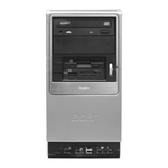
Page 11: Aspire T130 Front Panel
Front Panel The computer’s front panel consists of the following: Description Label Optical Drive Floppy Drive 6-in-1 Card Reader (Manufacturing Option) Power Button Speaker or Headphone Jack Microphone Jack USB Ports Description Description Chapter 1... -
Page 12: Aspire T130 Rear Panel
Rear Panel The computer’s rear panel consists of the following: Description Label Power Cord Socket Voltage Selector Switch Fan Aperture PS/2 Keyboard Port PS/2 Mouse Connector Serial Connector Printer Connector IEEE 1394 Port USB Connectors RJ-45 Ethernet Connector Microphone Jack Line-out Jack Line-In Jack Monitor Connector... -
Page 13: Main Board Layout
Mainboard Chapter 1... - Page 14 Lable AGP1 Accelerated Graphics Port (supports 1.5V AGP card only) ATX1 Standard 20-pin ATX power connector ATX2 Standard 4-pin ATX Power Connector AUDIO1 Front Audio Connector CASFAN1 Case fan connector CDIN1 Primary CD-in connector CPU FAN1 Cooling fan for CPU DIMM1~DIMM2 Three 184-pin DDR SDRAM FDD1...
-
Page 15: Block Diagram
Block Diagram AGP 8X SLOT 1394 connector 1394 header PCI VT6307 PCI SLOT 3 IDE 1 IDE 2 KEYBOARD /MOUSE 鶗廱嚽嚾黦龑顣鰎齙儹黤齝 鰗齠麚鼮囃麚龑 AMD-ATHLON64-CPU LINK0 16*16 AGP BUS SIS755 MuTIOL 1GMHz PCI SLOT 2 PCI SLOT 1 SiS964L PS/2 LPC Bus FAN CONTROL LPC Super I/O Legacy... -
Page 16: Hardware Specifications And Configurations
Hardware Specifications and Configurations Processor Item Type Socket Speed Voltage Front Side Bus BIOS Item BIOS code programmer BIOS vision BIOS ROM type BIOS ROM size BIOS ROM package Support Protocol Support to LS-120 drive Support to BIOS boot block feature NOTE: The BIOS can be overwritten/upgraded by using the flash utility. -
Page 17: System Memory
This section has two table lists, system memory specification and the possible combinations of memory module. System Memory Item Memory socket number Memory Controller Support memory size per socket Support maximum memory size Support memoryType Support memory Speed Support memory voltage Support memory module package Support to parity check feature Support to Error Correction Code (ECC) feature... - Page 18 This section has two table lists, the video interface specification and its supported display modes. Video Interface Item Video controller Video controller resident bus Video interface support Display Display Screen Resolution 640x480 640x480 640x480 640x480 640x480 800x600 800x600 800x600 800x600 800x600 800x600 800x600...
- Page 19 IDE Interface Item Chip Vendor Chip Name Number of IDE channel Support IDE interface Support bootable CD-ROM Floppy Disk Drive Interface Item Vendor & Mode Name Floppy Disk Specification Floppy Disk Drive Controlle Floppy Disk Drive Controller Resident Bus Support FDD format Parallel Port Item Parallel port controller...
-
Page 20: Usb Port
Modem Item Chipset Fax modem data baud rate (bps) Data modem data baud rate (bps) Voice modem Modem connector type Full duplex USB Port Item USB Compliancy Level EHCI Number of USB Port Location Serial Port Function Control PCI INTx# and IDSEL Assignment Map PCI INTx # INTA# AGP-slot... - Page 21 I/O Address Map Hex Range 170-177 1F0-1F7 278-27F 2F8-2FF 378-37F 3F0-3F5 3F6-3F6 3F7-3F7 3F8-3FF 0CF8 0CFC 778-77A IRQ Assignment Map IRQx IRQ0 Timer IRQ1 Keyboard IRQ2 Cascade Interrupt Control IRQ3 Serial Alternate IRQ4 Serial Primary IRQ5 MPU-401(Alternate) IRQ6 Floppy Disk IRQ7 Parallel Port IRQ8...
- Page 22 DRQ Assignment Map DRQx IRQ0 IRQ1 IRQ2 IRQ3 IRQ4 Cascade IRQ5 IRQ6 IRQ7 NOTE: N - Not be used Mainboard Major Chips Item System core logic Video controller Super I/O controller Audio controller HDD controller Keyboard controller IEEE1394 Environment Requirements Item Temperature Operating...
- Page 23 Input Voltage 200 - 240 VRMS Input Current NOTE: Measure at line input 90 VRMS and maximum load condition. Variation Range 180 - 264 VRMS Measuring Range 90 -132 VRMS 180 - 264 VRMS Chapter 1...
-
Page 24: Power Management Function (Acpi Support Function)
Power Management Function (ACPI support function) Device Standby Mode Independent power management timer for hard disk drive devices (0-15 minutes, time step=1 minute). Hard disk drive goes into Standby mode (for ATA standard interface). Disable V-sync to control the VESA DPMS monitor. Resume method: device activated (Keyboard for DOS, keyboard &... -
Page 25: Chapter 2 System Utilities
Chapter 2 System Utilities Most systems are already configured by the manufacturer or the dealer. There is no need to run Setup when starting the computer unless you get a Run Setup message. The Setup program loads configuration values into the battery-backed nonvolatile memory called CMOS RAM. This memory area is not part of the system RAM. -
Page 26: Bios Navigation Keys
BIOS Navigation Keys The BIOS navigation keys are listed below: Exits the current menu Scrolls through the items on a menu zxwy Modifies the selected field’s values +-{} Saves the current configuration and exits setup Displays a screen that describes all key functions Loads previously saved values to CMOS Loads a minimum configuration for troubleshooting Loads an optimum set of values for peak performance... -
Page 27: Entering Setup
Entering Setup Power on the computer and the system will start POST (Power On Self Test) process. When the message of “Press DEL to enter SETUP” appears on the screen, press NOTE: If the message disappears before you respond and you still wish to enter Setup, restart the system by turning it OFF and On. -
Page 28: Product Information
Product Information The screen below appears if you select Product Information from the main menu: The Product Information menu contains general data about the system, such as the product name, serial number, BIOS version, etc. These information is necessary for troubleshooting (may be required when asking for technical support). -
Page 29: Standard Cmos Features
Standard CMOS Features Select Standard CMOS Features from the main menu to configure some basic parameters in your system. Parameter Date Let’s you set the date following the weekday-month-day-year format Time Let’s you set the time following the hour-minute-second format IDE Channel 0 Master Lets you configure the hard disk drive connected to the master port... - Page 30 Parameter IDE Channel 1 Slave Lets you configure the hard disk drive connected to the slave port of IDE channel 1. To enter the IDE Channel 1 Slave setup, press e. The IDE CD-ROM is always automatically detected. Drive A Allows you to configure your floppy drive A.
-
Page 31: Ide Channel 0 Master/Slave And Ide Channel 1 Master/Slave
IDE Channel 0 Master/Slave and IDE Channel 1 Master/Slave The following screen appears if you select any of the IDE drive parameters: The following table describes the parameters found in this menu. Parameter IDE HDD Auto-Detection IDE Channel 0 Master/Slave IDE Channel 1 Master/Slave Access Mode Capacity... -
Page 32: Advanced Bios Features
Advanced BIOS Features This option defines advanced information about your system. Parameter Silent Boot This is to switch 1st screen logo (default Acer's logo) Configuration This is to select if system configuration shown by 2nd Table screen or not. Hard Disk Boot Selects the hard disk boot priority Priority Quick Power on... - Page 33 Parameter Second Boot The items allow you to set the sequence of boot device where Device BIOS attempts to load the disk operating system. Third Boot The items allow you to set the sequence of boot device where Device BIOS attempts to load the disk operating system. Boot Other This parameter allows you to specify the system boot up Device...
- Page 34 Parameter Typematic Rate After Typematic Rate Setting is enabled, this item allows you (Chars/sec) to set rate (characters/second) at which at keys are accelerated. Typematic This item allows you to select the delay between when the Delay key was first pressed and when the acceleration begins. Security Option If you have installed password protection, this item defines if the password is required at system start up, or if it is only...
-
Page 35: Advanced Chipset Features
Advanced Chipset Features These items define critical timing parameters of the mainboard. You should leave the items on this page at their default values unless you are very familiar with the technical specifications of your system hardware. If you change the values incorrectly, you may introduce fatal errors or recurring instability into your system. Parameter DRAM Configuration DRAM timing and control... - Page 36 DRAM Configuration Parameter HT_Width This item shows Hyper Transport TM ‘s bus size of Local Descriptor Table (LDT). The bus size is automatically calculated by the CPU. Therefore, we strongly recommend that you do not change this setting. HT_Speed This item shows the bus frequency of Local Descriptor Table(LDT).
-
Page 37: Integrated Peripherals
Integrated Peripherals These options display items that define the operation of peripheral components on the system’s input/ output ports. Parameter SIS OnChip IDE Device Press enter to setup the IDE device SIS OnChip PCI Device Press enter to setup the PCI device Onboard SuperIO Device Press enter to setup the superIO device IDE HDD Block Mode If your IDE hard drive supports block mode select... - Page 38 SiS OnChip IDE Device Scroll to this item and press <Enter> to view the following screen: Parameter Internal PCI/IDE IDE Primary Master PIO IDE Primary Slave PIO IDE Secondary Master PIO IDE Secondary Slave PIO Primary Master UDMA Primary Slave UDMA Secondary Master UDMA Secondary Slave UDMA Description...
- Page 39 SiS OnChip PCI Device Scroll to this item and press <Enter> to view the following screen: Parameter USB Controller This item is used to enable or disable the On-chip USB. USB 2.0 Supports Enable this item if you plan to use the Universal Serial Bus ports on this mainboard.
- Page 40 Onboard SuperIO Device Scroll this item and press <Enter> to view the following screen: Parameter Onboard FDC Controller This option enables the onboard floppy disk drive controller. Onboard Serial Port 1 This option is used to assign the I/O address and interrupt request (IRQ) for the onboard serial port 1 (COM1).
- Page 41 Parameter Parallel Port Mode Enables you to set data transfer protocol for your parallel port. There are four options: SPP (Standard Parallel Port), EPP(Enhanced Parallel Port), ECP(Extended Capabilities Port) and ECP+EPP. SPP allows data output only. Extended Capabilities Port (ECP) and Enhanced Parallel Port (EPP) are bi- directional modes, allowing both data input and output.
-
Page 42: Power Management Setup
Power Management Setup This option lets you control system power management. The system has various power-saving modes including powering down the hard disk, turning off the video, suspending to RAM, and software power down that allows the system to be automatically resumed by certain events. Parameter ACPI Suspend Type This item specifies the power saving modes for ACPI... - Page 43 Parameter Switch Function This option enables you to specify the function of the button: 1. Disabled: The button functions is disabled 2. Break/Wake: The button functions are same as suspend button in APM mode. When the button is depressed, the system enters a suspended state until the button is again depressed to return the system to normal operating status.
- Page 44 PM Wake Up Events Parameter IRQ [ 3-7, 9-15],NMI IRQ8 Break Suspend Power On by Ring Wake-Up by PCI Card USB KB Wake Up From S3 PS2KB Wakeup from S3 PS2MS Wakeup from S3 Resume by alarm Month Alarm Day of Month Alarm Time (hh:mm:ss) Alarm Description This option determines whether any activity for...
- Page 45 Parameter Primary IDE Secondary IDE FDD,COM,LPT Port PCI PIRQ [A-D]# Chapter 2 Description When these items are enabled, the system will restart the power-saving timeout conunters when any activity is detected on any of the drives on the primary or secondary IDE channel. When these items are enabled, the system will restart the power-saving timeout conunters when any activity is detected on any of the drives on the...
-
Page 46: Pnp/Pci Configuration
PnP/PCI Configurations These options configure how PnP (Plug and Play) and PCI expansion cards operate in your system. Both the ISA and PCI buses on the mainboard use system IRQs (Interrupt ReQuests) and DMAs (Direct Memory Access). You must set up the IRQ and DMA assignments correctly through the PnP/PCI Configurations Setup utility for the mainboard to work properly. - Page 47 Parameter PCI/VGA Palette Snoop Disabled - Data read or written by the CPU is only directed to the PCI VGA device’s palette registers. Enabled - Data read or written by the CPU is directed to both the PCI VGA device’s palette registers and the ISA VGA device’s palette registers, permitting the palette registers of both VGA devices to be identical.
-
Page 48: Pc Health Status
PC Health Status On mainboard that support hardware monitoring, this item lets you monitor the parameters for critical voltages, critical temperatures, and fan speeds. Parameter Shutdown Enables you to set the maximum temperature the Temperature system can reach before powering down. Description Option °... -
Page 49: Frequency Control
Frequency/Voltage Control This item enables you to set the clock speed and system bus for your system. The clock speed and system bus are determined by the kind of processor you have installed in the system. Parameter Auto Detect PCI/DIMM When this item is enabled, BIOS will disable the clock signal of free DIMM and PCI slots. -
Page 50: Load Default Settings
Load Default Settings You need to reload the BIOS default settings every time you make changes to your system hardware configuration (such as memory size, CPU type, hard disk type, etc.); otherwise, BIOS will keep the previous CMOS settings. Selecting this option displays the following dialog box: Parameter Load Default Settings Choosing Yes enables BIOS to automatically detect... -
Page 51: Set Supervisor/User Password
Set Supervisor/User Password Parameter Set Supervisor Password Set User Password Chapter 2 Description To set a password: At the prompt, type your password. Your password can be up to 8 alphanumeric characters. When you type the characters, they appear as asterisks on the password screen box. -
Page 52: Save&Exit Setup
Save & Exit Setup Parameter Save&Exit Setup Highlight this item and press <Enter> to save the changes that you have made in the Setup Utility and exit the Setup Utility. When the Save and Exit dialog box appears, press <Y> to save and exit, or press <N>... -
Page 53: Exit Without Saving
Exit Without Saving Parameter Exit Without Saving Highlight this item and press <Enter> to discard any changes that you have made in the Setup Utility and exit the Setup Utility. When the Exit Without Saving dialog box appears, press <Y> to discard changes and exit, or press <N>... -
Page 54: Chapter 3 Machine Disassembly And Replacement
NOTE: The Aspire T130 mechanical housing is similar to AcerPower F1. Therefore, this chapter base on F1 to have minor rectify but the CPU and Heatsink are different between the two models. -
Page 55: General Information
General Information Before You Begin Before proceeding with the disassenbly procedure, make sure that you do the following: Turn off the power to the system and all peripherals. Unplug the AC adapter and all power and signal cables from the system. Chapter 3... -
Page 56: Disassembly Procedure Flowchart
Disassemble Flow Chart Chapter 3... -
Page 57: Standard Disassembly Procedure
CAUTION: Before you proceed, make sure you have turned off the system and all peripherals connected to it. NOTE: The Aspire T130 mechanical housing is similar to AcerPower F1. Therefore, this chapter base on F1 to have samll rectify but the CPU and Heatsink are different between the two models. -
Page 58: Removing The Modem Card, Cd-Rom, Floppy And Hdd
Disconnect the CD-In cable. Disconnect the floppy cable. Disconnect the IDE1 and IDE2 cable. Removing the Modem card, CD-ROM, Floppy and HDD NOTE: There have the hook lock on CD-ROM, floppy and HDD cage, in other words, please move a little bit forward to release the lock then you can disassemble these parts smoothly. -
Page 59: Removing The Power Supply
Press the latch and remove the CD-ROM drive. Press the latch and remove the floppy drive. Press the latch again to release the hard disk module. Detach the HDD from the bracket. Removing the Power Supply Remove the main ATX power connector as shown here. Remove the Pentium 4(ATX-12V) power connector as shown here. -
Page 60: Removing The Heatsink And Cpu
Remove the power supply. Removing the Heatsink and the CPU ( for T130) First of all, disconnect the CPU fan power cable. Remove the 4 screws first. Take the CPU fan after you remove screws. Press the latch outward with a flat screw driver to release it. -
Page 61: Removing The Memory
Removing the Memory Pop out the memory and remove it as shown here. Removing the Mainboard Remove the six screw as shown here. Remove the motherboard as shown here. Removing the Power Button Remove the power button as shown here. Removing the LED Module Remove the LED module by following the instructions here. -
Page 62: Removing The Daughter Board
Removing the Daughter Board Remove the screw as shown here. Detach the USB cable and audio cable from the daughter board. Chapter 3... -
Page 63: Standard Reassembly Procedures
Standard Reassembly Procedure This section tells you how to reassemble the system when you need to perform system service. Please also refer to the assembly video, if available. Installing the Daughter Board Connect the audio cable and USB cables to the daughter board. Fasten the daughter board with one screw as shown here. -
Page 64: Installing The Cpu And Heatsink Module
Secure the motherboard with the six screw as shown here. Installing the Heatsink and the CPU (please refer to disassemble photos) Place the CPU to the CPU socket. Place the rentention module next to previous installing. Place the heatsink then hook the latch to the tabs. Then place the CPU fan on the heatsink. -
Page 65: Installing The Modem Card, Cd-Rom, Floppy And Hdd
Connect the main ATX power connector to the motherboard as shown here. Installing the Modem card, CD-ROM, Floppy and HDD NOTE: There have the hook lock on CD-ROM, floppy and HDD cage, in other words, please move a little bit forward to release the lock then you can install these parts smoothly. Insert the HDD to the bracket by following the instructions here. -
Page 66: Installing The Cables
Connect the CD-ROM power, IDE and CD-In cables. Place the modem card back to one PCI slot. Then secure the modem card with the screw. Installing the Cables Connect the IDE1 and IDE2 cable to the motherboard. Connect the floppy cable to the motherboard. Connect the CD-In cable to the motherboard. -
Page 67: Install The Front Panel
Installing the Front Panel Place the front bezel back to the original position. Closing the System Place the side door back to the original position. Secure the side door with the two screws as shown here. Chapter 3... -
Page 68: Chapter 4 Troubleshooting
Chapter 4 Troubleshooting This chapter provides troubleshooting information for the Aspire T130: Power-On Self-Test (POST) Index of Error Messages Index of Error Codes and Error Beeps Index of Error Symptoms Undetermined Problems Chapter 4... -
Page 69: Power-On Self-Test (Post)
Power-On Self-Test (POST) Each time you turn on the system, the Power-on Self Test (POST) is initiated. Several items are tested during POST, but is for the most part transparent to the user. The Power-On Self Test (POST) is a BIOS procedure that boots the system, initializes and diagnoses the system components, and controls the operation of the power-on password option. -
Page 70: Post Check Points
POST Check Points When POST executes a task, it uses a series of preset numbers called check point to be latched at port 80h, indicating the stages it is currently running. This latch can be read and shown on a debug board. The following table describes the Acer common tasks carried out by POST. - Page 71 Checkpoint Description Reserved Use walking 1’s algorithm to check out interface in CMOS circuitry. Also set real-time clock power status, and then check for override. Reserved Program chipset default values into chipset. Chipset default values are MODBINable by OEM customers. Reserved Initial onboard clock generator if Early_Init_Onboard_Generator is defined.
-
Page 72: Post Error Messages List
Checkpoint Chapter 4 Description 1. Program CPU internal MTRR (P6 & PII) for 0-640K memory address. 2. Initialize the APIC for Pentium class CPU 3. Program early chipset according to CMOS setup. Example: onboard IDE controller. 4. Measure CPU speed. Reserved Invoke Video BIOS Reserved... - Page 73 Checkpoint Description Reserved Reserved 1. Program MTRR of M1 CPU 2. Initialize L2 cache for P6 class CPU & program CPU with proper cacheable range. 3. Initialize the APIC for P6 class CPU. 4. On MP platform, adjust the cacheable range to smaller one in case the cacheable ranges between each CPU are not identical.
- Page 74 Checkpoint Chapter 4 Description Program chipset registers according to items described in Setup & Auto-configuration table Reserved 1. Assign resources to all ISA PnP devices. 2. Auto assign ports to onboard COM ports if the corre- sponding item in Setup is set to “Auto”. Reserved 1.
- Page 75 Checkpoint Description Reserved 1. Assign IRQs to PCI devices. 2. Set up ACPI table at top of the memory. Reserved 1. Invoke all ISA adapter ROMs 2. Invoke all PCI ROMs (except VGA) Reserved 1. Enable/Disable Parity Check according to CMOS setup.
-
Page 76: Error Symptoms List
POST Error Messages List If you cannot run the diagnostics program tests but did receive a POST error message, use “POST Error Messages List” to diagnose system problems. If you did not receive any error message, look for a description of your error symptoms in “Error Sympton List”. - Page 77 BIOS Messages Floppy Drive(s) Write Protected Hard Disk Drive(s) Write Protected IDE Drive 0 Error IDE Drive 1 Error IDE Drive 2 Error IDE Drive 3 Error IRQ Setting Error Expansion ROM Allocation Fail I/O Resource Conflict(s) Memory Resource Conflict(s) PCI Device Error PS/2 Pointing Device Interface Error PS/2 Pointing Device Error...
- Page 78 Error Symptoms List NOTE: To diagnose a problem, first find the error symptom in the left column. If directed to a check procedure, replace the FRU indicated in the check procedure. If no check procedure is indicated, the first Action/ FRU listed in right column is the most likely cause Error Symptom NOTE: Normally, the processor fan should be operative, and the processor clock setting should be...
- Page 79 Error Symptom Diskette drive does not work. Diskette drive read/write error. Diskette drive LED comes on for more than 2 minutes when reading data. Diskette drive LED fails to light, and the drive is unable to access for more than 2 minutes.
- Page 80 Error Symptom CD/DVD-ROM drive LED flashes for more than 30 seconds before LED shutting off. Software asks to reinstall disc. Software displays a reading CD/DVD error. CD/DVD-ROM drive cannot load or eject when the system is turned on and its eject button is pressed and held.
- Page 81 Error Symptom Display problem: - Incorrect colors No high intensity Missing, broken, or incorrect characters Blank monitor(dark) Blank monitor(bright) Distorted image Unreadable monitor Other monitor problems Display changing colors. Display problem not listed above (including blank or illegible monitor). Action/FRU 1.
- Page 82 Error Symptom Execute “Load BIOS Default Settings” in BIOS Setup to confirm ports presence before diagnosing any parallel/serial ports problems. Serial or parallel port loop-back test failed. Printing failed. Printer problems. Some or all keys on keyboard do not work. Pressing power switch does not turn off system.
-
Page 83: Chapter 5 Jumper And Connector Information
Jumper and Connector Information Before setting jumpers Use the mainboard jumpers to set system configuration options. Jumpers with more than one pin are numbered. When settting the jumpers, ensure that the jumper caps are placed on the correct pins. Illustration Short Open Chapter 5... -
Page 84: Header Definition
Header Definition Name CPUFAN1 AMP640456-3 CASFAN1 AMP640456-3 PWRFAN1 AMP640456-3 COM1 CONN-9P2R-90M USB1394A2 USB-DUAL/1394 USB1 H5*2 USB2 H5*2 USB3 H5*2 FDD1 H17*2LW IDE1 H20*2LW IDE2 H20*2LW PANEL1 H5*2 AUDIO1 H5*2 SPDIF H3*1 ATX1 PW_20P2R ATX12V AXT_PWR_CON4A Connector Type CPU FAN Chassis Fan Power Fan Serial Port 1 1394 and USB connector... - Page 85 Jumper and Connector Settings The following illustration shows the location of the mainboard jumpers. Pin 1 is labeled. Jumper Type 3-pin Clear CMOS Use this jumper to clear the contents of the CMOS memory. You may need to clear the CMOS memory if the settings in the Setup Utility are incorrect and prevent your mainboard...
- Page 86 V: ATX V Power Connector : ATX -pin Power Connector Signal Name +3.3V +3.3V Ground Ground Ground PWRGD +5VSB +12V Signal Name +12V +12V Ground Ground Signal Name +3.3V -12V Ground PS ON# Ground Ground Ground Chapter 5...
- Page 87 CPUFAN /CASFAN /PWRFAN Front Side View Pinout Top-View Chapter 5 : FAN Power Connector Signal Name +12V Sense Signal Name Ground Signal Name STROBE BUSY Function System Ground Power +12V Sensor Signal Name SLCT ERROR INIT SLCTIN GROUND GROUND GROUND GROUND GROUND GROUND...
- Page 88 PSKBM PS/2 Mouse PS/2 Keyboard USBLAN PS/2 Keyboard KBDATA GROUND KBCLK Signal Name -DATA0 +DATA0 -DATA1 +DATA1 HOLE_USB HOLE_USB HOLE_USB HOLE_USB HOLE_LAN HOLE_LAN PS/2 Mouse MDATA GROUND MCLK Signal Name HOLE_LAN HOLE_LAN HOLE_LAN HOLE_LAN PLED0 PLED1 Chapter 5...
- Page 89 , USB Signal Name GROUND GROUND KEYPIN GROUND GROUND GROUND GROUND GROUND GROUND GROUND GROUND GROUND GROUND GROUND GROUND GROUND GROUND Chapter 5 Signal Name Signal Name USBPWR0 USBPWR1 USB0- USB1- USB0+ USB1+ Signal Name DRVDEN0 HDL- DS3- INDEX- MTR0- DS0- DS1- MTR1-...
- Page 90 , IDE Signal Name RESET- GROUND DMARQ DIOW- DIOR- IORDY DMACK- INTRQ CS1FX- DASP- Signal Name NDCDB NSOUTB NRTSB NRIB Signal Name GROUND DD10 DD11 DD12 DD13 DD14 DD15 KEYPIN GROUND GROUND GROUND PSYNC:CSEL GROUND IOCS16- PDIAG- CS3FX- GROUND Signal Name NSINB NDTRB NDSRB...
- Page 91 PANEL 1394A AUDIO Chapter 5 Signal Name HD_LED_P HD_LED_N RST_SW_N RST_SW_P RSVD Signal Name HD_LED_P HD_LED_N RST_SW_N RST_SW_P RSVD Signal Name AUD_MIC MIC_BIAS AUD_F_R REVD AUD_F_L Signal Name PWR_SLP PWR_SLP PWR_SW_P PWR_SW_N Signal Name PWR_SLP PWR_SLP PWR_SW_P PWR_SW_N Signal Name AUD_GND AUD_VCC AUD_RET_R...
- Page 92 Front Panel Connector The front panel connector (PANEL1) provides a standard set of switch and LED connectors commonly found on ATX or micro-ATX cases. Refer to the table below for information: Singal Name Function HDDLED Hard disk LED(positive) HDDLED Hard disk active LED (negative) RST_SW_N Reset Switch...
-
Page 93: Chapter 6 Fru (Field Replaceable Unit) List
FRU (Field Replaceable Unit) List This chapter gives you the FRU (Field Replaceable Unit) listing in global configurations of Aspire T130. Refer to this chapter whenever ordering for parts to repair or for RMA (Return Merchandise Authorization). NOTE: Please note WHEN ORDERING FRU PARTS, that you should check the most up-to-date information available on your regional web or channel account, you can still access the system with guest;... -
Page 94: Exploded Diagram
Aspire T130 Exploded Diagram Chapter 6... -
Page 95: Spare Parts
Spare Parts Category Partname BOARD USB/AUDIO DAUGHTER BOARD FOXCONN CABLES IDE CD-ROM CABLE ATA66 40PIN IDE FDD CABLE 34PIN AUDIO CABLE 8PIN 2CON FRONT INTERNAL USB CABLE CASE/ FRONT BEZEL W/POWER COVER/ BUTTON. 5.25”, 3.5” EMPTY BRACKET COVER, USB DOOR ASSEMBLY POWER BUTTON SIDE DOOR... - Page 96 Category Partname DVD-RW 4X DVD SUPERMULTI DRIVE PLUS(BLACK) HLDS GSA- 4040B BLACK W/O ACER LOGO FANSINK FAN SINK FOR ATHLON 64 FAN SINK FOR ATHLON 64 SYSTEM FAN CUP/ ATHLON 64 3200+ PROCESS (CLAWHANMMER) ATHLON 64 3000+ (CLAWHAMMER) FDD/ FDD 1.44MB PANASONIC FLOPPY JU-256A048P BLACK DISK...
- Page 97 Category Partname KEYBOARD USB KB(SILVER), KU0355, US VER., 104 KEYS USB KB (SILVER), KU0355, ARBIC VER., 104KEYS USB KB (SILVER), KU0355, GERMANY VER., 105KEYS USB KB (SILVER), KU0355, ITALIAN VER., 105KEYS USB KB (SILVER), KU0355, FRENCH VER., 105KEYS USB KB (SILVER), KU0355, SWEDEN VER., 105KEYS WIRELESS KB(SILVER), KBR0355, US VER.,104...
- Page 98 Category Partname MAINBOAR MB E31M W/1394, USB2.0, LAN, AUDIO ECS 755-M MAINBOAR MB CONVERTER USED IN AUDIO/ USB/ LED CONVERTE MEMORY DDR333 256MB HYS64D32300GU-6-B 32MX8*8(.14U) DDRHYS64D64300GU-6-B/ INFINEON DDR333 256MB NT256D64S88B1G-6K (0.14U) 32MX8 DDR333 512MB NT512D64S8H (0.14U)32MX8 POWER POWER SUPPLY 230W W SUPPLY PFC FSP 200-ATV(A)(PF) POWER SUPPLY 230W W/...
-
Page 99: Appendix A Model Definition And Configuration
Model Definition and Configuration The Aspire T130 Model No. Define: Trade Mark: Brand Name: Acer Description: Mainboard E31M,W/1394, USB2.0, LAN and Audio Model No: Aspire T130 Product Name: Acer Aspire T130 Appendix A Appendix A... -
Page 100: Appendix B Test Compatible Components
Appendix B Test Compatible Components Aspire T130 compatibility is tested and verified by Acer’s internal testing department. All of its system functions are tested under the environments of Windows XP Home. Appendix B... -
Page 101: Microsoft Windows Xp Home Environment Test
Microsoft Windows XP Home Environment Test COMPONENTS MAIN BOARD MAINBOARD E31M, W/1394, USB 2.0, LAN, AUDIO CONVERTER FOR ASPIRE T130 CHASSIS CPU (400MHZ) ATHLON 64 3200+(CLAWHAMMER) ATHLON 64 3000+(CLAWHAMMER) CP FAN SINK FOXCONN FOXCONN FANSINK FOR ATHLON 64 DIMM (DDR 333) INFINEON DDR 333 256MB 0.14U 32M*8*8... - Page 102 COMPONENTS SAPPHIRE ATI RADEON 9200SE 128MB DDR W/TV OUT (PAL), ATX BRACKET ATI RADEON 9600SE 128MB DDR W/TV OUT (PAL), ATX BRACKET ATI RADEON 9800SE 128MB DDR W/TV OUT (PAL), ATX BRACKET MODEM ASKEY V92 56K HSFI F-1156I(+)/R12(EU) ATX HOUSING FOXCONN MICRO TOWER SPS (SWITCH POWER SUPPLY)
- Page 103 COMPONENTS CHICONY USB KB(SILVER), KU0355, US VER., 104 KEYS USB KB(SILVER), KU0355, ARABIC VER., 104 KEYS USB KB(SILVER), KU0355, GERMANY VER., 105 KEYS USB KB(SILVER), KU0355, ITALIAN VER., 105 KEYS USB KB(SILVER), KU0355,FRENCH VER., 105 KEYS USB KB(SILVER), KU0355, SWEDEN VER., 105 KEYS USB KB(SILVER), KU0355, UK VER., 105 KEYS...
- Page 104 COMPONENTS 17" CRT MON.AC713 BLACK MPRII N.M. EUR P.C. AEB 17" CRT MON.AC713 BLACK MPRII N.M. UK P.C. AEB 17" CRT MON.AC713 BLACK MPRII E.M. W/O P.C.AAP 17" CRT MON.AC713 BLACK MPRII N.M. W/O P.C. AAP 17" CRT MON.AC713 BLACK MPRII S.M. AUSTRALIA P.C.
- Page 105 COMPONENTS 17” LCD MONITOR 15 LCD M N. AL1531 TC99 EUR. SWISS UK P.C. AEB 15 LCD M N. AL1531 TC99 W/P WER C RD AAP 15 LCD M N. AL1531 TC99 UK P WER C RD AAP 15 LCD M N. AL1531 TC99 EUR P WER C RD AAP 15 LCD M N.
-
Page 106: Online Support Information
Online Support Information This section describes online technical support services available to help you repair your Acer Systems. If you are a distributor, dealer, ASP or TPM, please refer your technical queries to your local Acer branch office. Acer Branch Offices and Regional Business Units may access our website. However some information sources will require a user i.d.