Sign In
Upload
Manuals
Brands
ABB Manuals
Accessories
LevelMaster 7100
ABB LevelMaster 7100 Manuals
Manuals and User Guides for ABB LevelMaster 7100. We have
3
ABB LevelMaster 7100 manuals available for free PDF download: User Manual, Application Manual, Quick Start
ABB LevelMaster 7100 User Manual (100 pages)
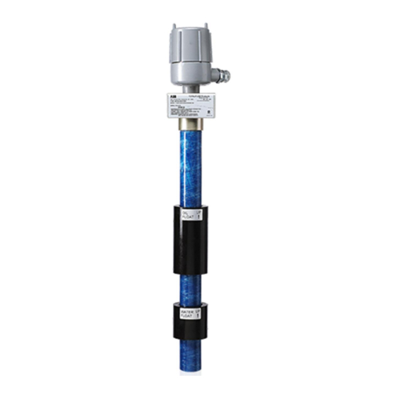
Liquid level sensor with batteryless float support
Brand:
ABB
| Category:
Accessories
| Size: 3.97 MB
Table of Contents
Table of Contents
3
Typographical Conventions
8
Additional Information
9
1 Health and Safety
11
General Information and Notes
11
Safety, Warning, and Note Symbols
11
Safety Requirements for Installation
12
2 System Description
13
Overview
13
Figure 1: Typical Levelmaster Oil and Water Tank Installation
13
General Specifications
14
Levelmaster Components
14
Table 1: General Levelmaster Specifications
14
Software Interfaces
16
Installation Scenarios
17
Figure 2: Typical Levelmaster Configuration for General-Purpose Locations
18
Figure 3: Levelmaster Configuration Example for a Hazardous Location
18
Figure 4: Installation with High Level Auxiliary Switch (12-Inch Option)
19
3 Installation
20
Site Planning and Requirements
20
Unpack and Inspect
21
Figure 5: Levelmaster Group D Hazardous Location Installation
21
Figure 6: Levelmaster Components in Typical Installation
22
Table 2: Levelmaster Parts List
23
Table 3: Levelmaster Optional Parts List
23
Table 4: Cables and Adapters for Direct Connection to the Levelmaster
24
Assembly
25
Figure 7: Masterlink Communication Cable (for Boards with Part Number 2104836-001)
25
Figure 8: Masterlink Communication Cable (for Boards with Part Number 2018546-005)
25
Figure 9: Cord Connector and Tank Port Bushing Installation
26
Figure 10: Single Float Assembly
26
Install or Set the Position of the High Level Auxiliary Switch (Optional)
27
Figure 11: Dual Float Assembly
27
Figure 12: Casing Clamp Installation
27
Figure 13: High Level Auxiliary Switch Installation
28
Figure 14: Auxiliary Float Switch for Normally Open (NO) Operation
28
Insert the Unit into the Tank
29
Figure 15: Auxiliary Float Switch Height Adjustment
29
Figure 16: Tank Port Bushing Installation
30
Figure 17: Nut and Body Installation
31
4 Wiring
32
Board Versions Overview
32
Figure 18: Communication and Power Ports Pinouts
32
Figure 19: Removing Terminal Connectors (2104836-001)
33
Figure 20: RS-485 Termination for Legacy Board (Part Number 2018546-005)
33
Selecting Wire Type
34
Wiring the First Levelmaster
34
Figure 21: Wiring for Communication with Host Controller (First or Only Levelmaster)
34
Figure 22: Wiring for Power (Single Board Installation)
35
Wiring Additional Levelmasters
36
Figure 23: General Schematic of a Multi-Levelmaster Bus (General Purpose Location)
37
Table 5: Wiring Limits on the RS-485 Bus
37
Figure 24: Two-Levelmaster RS-485 Bus of same Board Type Using both Communication Contact Pairs
39
Figure 25: Three-Levelmaster RS-485 Bus (same Board Type)
39
Figure 26: Two-Levelmaster RS-485 Bus of same Board Type Using Single Communication Contact Pair
40
Figure 27: Two-Levelmaster RS-485 Bus (Mixed Board Type)
40
Wiring the Host Controller
41
Figure 28: Levelmaster Wiring to Different Types of ABB Totalflow Host Controllers
42
Figure 29: Wiring the Levelmaster to an XFC
43
Figure 30: Wiring the Levelmaster to the RMC-100 (Onboard COMM Port)
44
Figure 31: Wiring the Levelmaster to Ethernet-To-Serial Converter and the RMC-100
44
Figure 32: Totalflow CSA-Certified Barrier Board
45
Table 6: Wiring Limitations When Using Barrier Boards
45
Figure 33: Wiring the Levelmaster to the Barrier Board
46
Applying Power to the Levelmaster
47
Grounding
47
Figure 34: Levelmaster Wiring to Different Types of ABB Totalflow Host Controllers through a Safe Barrier
47
Figure 35: Grounding the Electronics Board
48
5 Configuring Levelmasters Using Masterlink
49
Installing Masterlink
49
Connecting to the Levelmaster
49
Figure 36: Cable and Adapters for Local Communications (2104836-001 Boards)
50
Figure 37: Cable and Adapters for Local Communication (2018546-005 Boards)
50
Configuring the First Levelmaster
51
Figure 38: Connecting the Laptop to the Electronics Board
51
Figure 39: Masterlink Main Screen
52
Figure 40: New Levelmaster Setup
53
Figure 41: Masterlink Monitor Tab
54
Figure 42: Masterlink Setup Tab
54
Figure 43: RS-485 Termination
55
Figure 44: Configure the Levelmaster to Terminate the RS-485 Bus
56
Figure 45: RS-485 Termination Configuration for Only or Last Levelmaster
56
Configuring Additional Levelmasters
58
6 Configuring the Host Controller
60
Activate the Levelmaster Application
60
Table 7: PCCU32 Versions Supporting the Levelmaster Application
60
Set up General and Communications Parameters
62
Figure 46: Activating the Levelmaster Application
62
Figure 47: Levelmaster Application Setup Tab
63
Figure 48: Levelmaster Application Communications Tab
63
Set up the Levelmaster Request Blocks Files
64
Figure 49: Levelmaster Application Request Block Files
64
Configure the LCD Display
65
Verify Basic Configuration
65
Configuring for Data Collection
66
Figure 50: Verifying Level and Temperature Measurements Are Received by Host Controller
66
Figure 51: Determining Register Address for Levelmaster Measurement Values (Levels Tab)
67
Figure 52: Adding a Variable (Measurement) to Trend
68
Save the Configuration
69
Figure 53: Verifying Trending of the Levelmaster Data (Example)
69
Duty Cycling Power (Optional)
70
Table 8: Duty Cycle Parameters
70
Push-To-Read (Optional)
71
Figure 54: Host Hardware Digital Outputs
71
Figure 55: Host Hardware Digital Inputs
71
7 Calibration from the Host Controller
72
Calibration for Level Measurement (Level Bias)
72
Figure 56: Adding Level Bias from PCCU
72
Calibration for Volume Calculations
73
Figure 57: Configuring the Strapping Table
74
8 Service and Maintenance
75
Remove the Enclosure Cover
75
Remove Field Wiring
76
Figure 58: Removing the Electronics Enclosure Cover
76
Restore Field Wiring
77
Remove the Unit from the Tank
77
Figure 59: Removing the Unit from Tank
77
Reinstall the Unit into the Tank
78
Remove the Enclosure from the Casing
78
Figure 60: Removing Electronic Enclosure from Casing
78
Reinstall the Enclosure on the Casing
79
Establish Local Communication with Electronics Board
79
Preserve Sensor Data and Configuration
80
Restore Sensor Data and Configuration
80
Upgrade the Electronics Board
81
Replace the Electronics Board
81
Figure 61: Masterlink Upload/Download Tab
83
Figure 62: Locating the Correct Factory Default Configuration File
85
Figure 63: Levelmaster Upload/Download Tab
85
Figure 64: Levelmaster Setup Tab for ID and Baud Rate Configuration
86
Figure 65: Inserting New Floats
87
Replace Floats
87
Replace the Sensor Assembly
88
Move a Levelmaster from One Tank to Another
90
9 Troubleshooting
91
Table 9: Error Messages for Board Part Number 2018546-005 (Firmware Versions 5.015 - 5.018)
91
Table 10: Troubleshooting New Installations
92
Table 11: Troubleshooting an Existing Installation
94
Appendix A Tank Level Pass-Through
96
Levelmaster Protocol Commands
96
Table 12: Commands for TLPT for Board Part Number 2018546-005 (Firmware Versions 5.015 - 5.018)
96
Table 13: Commands for TLPT for Board Part Number 2104836-001 (Firmware Version 7.000)
96
Activating the Tank Level Pass-Through
97
Contact Us
100
Advertisement
ABB LevelMaster 7100 Application Manual (28 pages)
Liquid level sensor, Upgrade kit, Upgrade to support batteryless floats
Brand:
ABB
| Category:
Accessories
| Size: 1.78 MB
Table of Contents
Additional Information
2
Safety Conventions
3
Upgrade Procedures
8
View Configuration
10
Save the Configuration
11
Wiring for Power
19
Troubleshooting
24
ABB LevelMaster 7100 Quick Start (2 pages)
Brand:
ABB
| Category:
Measuring Instruments
| Size: 0.36 MB
Advertisement
Advertisement
Related Products
ABB 718B820A09
ABB 718B820A12
ABB 717B770A15
ABB 717B770A17
ABB 717B770A18
ABB 717B770A20
ABB 717B770A21
ABB 717B770A24
ABB 717B770A25
ABB 717B770A27
ABB Categories
Industrial Equipment
Controller
Measuring Instruments
Battery Charger
DC Drives
More ABB Manuals
Login
Sign In
OR
Sign in with Facebook
Sign in with Google
Upload manual
Upload from disk
Upload from URL