Table of Contents
Advertisement
Quick Links
Download this manual
See also:
User Manual
Application guide
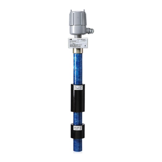
Liquid level sensor
LevelMaster 7100
Upgrade kit
Upgrade to support batteryless floats
Introduction
This guide is designed for typical installations only. Service and maintenance must
be performed by personnel knowledgeable of the ABB Totalflow
Maintenance personnel must also be knowledgeable of local and national codes as
they apply to hazardous areas, communication wiring, and electrical wiring.
IMPORTANT NOTE:This guide does not address any requirements
for the removal or installation of product(s) in hazardous (classified)
locations. Refer to the installation instructions and local and national
electrical codes for installation requirements in hazardous (classified)
locations.
Purpose
This guide provides instructions and information for upgrading an existing electronic
headboard (2018546-005) and battery-driven (active) floats with the new headboard
(2104836-001) and batteryless floats.
®
LevelMaster.
Advertisement
Table of Contents

Related Manuals for ABB LevelMaster 7100


Summary of Contents for ABB LevelMaster 7100
- Page 1 Introduction This guide is designed for typical installations only. Service and maintenance must ® be performed by personnel knowledgeable of the ABB Totalflow LevelMaster. Maintenance personnel must also be knowledgeable of local and national codes as they apply to hazardous areas, communication wiring, and electrical wiring.
-
Page 2: Additional Information
The upgrade kit can be used to upgrade the unit for single or dual batteryless float operation. — MasterLink software version 2.0 is used to configure the upgraded LevelMaster. — If the LevelMaster is connected to an ABB flow computer or remote controller, the LevelMaster application should already be configured. -
Page 3: Safety Conventions
1 Safety warning and notes symbols Read and follow the instructions contained in this guide, before and during equipment installation. Failure to do so could result in bodily injury or equipment damage. Safety conventions WARNING – Bodily injury/property damage/equipment damage. This symbol, in conjunction with the signal word "WARNING", indicates a potentially dangerous situation. - Page 4 3. Unpack and inspect optional equipment, if purchased. 4. Check for missing, incorrect, or damaged parts. Contact the ABB Representative to replace missing, incorrect, or damaged parts. 4 | 2105824-001 rev. AA...
- Page 5 3 Prepare before the upgrade Plan for unit access removal and reinstallation Upgrading the LevelMaster for batteryless float support requires removal of all connections and pulling the LevelMaster out of the tank. Plan for the following: Removal of the unit requires access to the top of the tank. Follow company guidelines and safety procedures to access the sensor.
- Page 6 Determine which configuration to use based on the upgrade scenario: — Use the existing configuration if available. The configuration file of the LevelMaster contains calibration information for the internal sensor assembly (sensor coil). Since the sensor assembly is not being changed in the upgrade, the calibration data remains the same and it is still applicable to the unit.
- Page 7 Table 2: Cable and adapters for direct connection to the LevelMaster Board Description Part number Notes Cable end connecting to the board has a 2-position terminal connector for power and a 4-position terminal Cable adapter 2100250 - 002 connection for the communication port (RS485) See Figure 1.
-
Page 8: Upgrade Procedures
4 Upgrade procedures Remove the sensor from the tank Removal of the sensor requires removal of power and other connections from the LevelMaster. Devices that may be connected to the LevelMaster may include additional LevelMasters (RS485 bus), flow computers or controllers, an electronic barrier card for hazardous locations. - Page 9 Remove the wires from the connector(s). If two connectors were removed, keep for rewire. Hold the existing board by the edges, and pull it out slowly. Unplug the 16-pin connector at the bottom of the board to detach the board from the sensor assembly inside the casing.
-
Page 10: View Configuration
Obtain existing configuration file With this procedure use the MasterLink software to view or obtain the configuration of the unit if the configuration file was not previously saved. It is assumed that the existing board removed in section 4.1 is in working condition. If the board is defective or communication with it is no longer possible, proceed to section 4.4, Insert the new electronic board. -
Page 11: Save The Configuration
Sensor name Sensor unit number (or sensor or LevelMaster ID) Baud Rate Coil length (sensor assembly length in inches) Determine the RS485 bus termination configuration by checking the positions of the jumpers on JP1 on the board (Figure 4): Pins 5-6 and 9-10 are jumpered (factory default). The unit is an intermediate sensor on the bus. - Page 12 RS485 PORT POWER PORT REMOVE TERMINAL CONNECTORS Figure 5: Removing terminal connectors Plug the 16-pin connector from the sensor assembly into the new electronic board. The connector is keyed so it will only plug in one way. Push some of the excess cable back down through the bottom of the sensor assembly while sliding the electronic board back into position.
- Page 13 Under Send data to the LevelMaster from the file, click the browse ([…]) button. At the browser, navigate to the folder where the existing configuration file was saved (for example, C:\Program Files (x86)\ABB\MasterLink). Locate and select the configuration file. Click Open.
- Page 14 Under Send data to the LevelMaster option, click Browse […]. At the browser, navigate to the default files folder applicable to the new board. For example, C:\Program Files (x86)\ABB\MasterLink\DefaultDat\7.0 Head board. Locate the file for the correct length of sensor and click Open.For example, for a 20 foot sensor, select the "Dual_20ft_batteryless.dat"...
- Page 15 Figure 7: Downloading correct configuration to the LevelMaster Click Download Data to LevelMaster. Click OK when the download is complete. Click the Setup tab (Figure 8). Figure 8: Configure the ID and Baud Rate 2105824-001 rev. AA | 15...
- Page 16 Change the LevelMaster ID by typing the correct ID into the New LevelMaster ID field and clicking Set New ID. 10. If needing to set another Baud rate, click Set <…>Baud Rate. The next applicable value for the baud rate is the one shown on the button. For example, if the value shown is 19200, clicking on the button, will set the rate to 19200.
- Page 17 Double-click on RS485 bus termination. When the edit box displays (Figure 10), if the value is 0, change the value to one (1). The value of 1 configures the unit as the last sensor on the RS485 bus. Figure 10: Configure the LevelMaster to terminate RS485 bus Click Send New Value.
- Page 18 4.8, Reinstall the LevelMaster into the tank. Ground the electronic board WARNING – Bodily injury/ property damage. Grounding the LevelMaster 7100 in a hazardous location must meet the requirements as specified in the National Electrical Code (NEC) or the Canadian Electrical Code (CEC).
-
Page 19: Wiring For Power
RS485 in the previous board does not match that of the new board. Figure 13: Electronic ports pinouts For additional details on the connections to other ABB equipment refer to the LevelMaster user manual (see Additional Information section). - Page 20 CAUTION – Equipment damage. The LevelMaster can be powered from the serial (COM) ports on an ABB Totalflow flow computer or remote controller. The output voltage at these ports is dependent upon the external power supply connected to the device.
- Page 21 To flow computer or remote controller T- T- T+ T+ POWER EARTH Figure 15: Wiring for communication: new board as the only sensor If the unit is connected to a multiple-unit RS485 bus, wire as shown in Figure 16, Figure 17 (page 22) or Figure 18 (page 22). ®...
- Page 22 4.10 Verify installation using PCCU If the LevelMaster is connected to an ABB Totalflow flow computer or remote controller, verify that the LevelMaster communication interface is able to detect the unit and that the correct measurements are being displayed.
- Page 23 Select the tank tab. For example Tank1 tab. The tank measurements, sample time stamp, poll and error counts should display (Figure 19). Figure 19: Verify sensor measurements from PCCU Verify that the temperature measurement is the expected value. It must reflect the temperature in the tank.
-
Page 24: Troubleshooting
5 Troubleshooting Review the common error messages and solutions included in this section. If unable to resolve problems after the upgrade, refer to the LevelMaster user manual or see the contact information in the back of this guide to call for support. Errors observed on the MasterLink The following are common errors displayed when using the MasterLink software to connect with the LevelMaster. - Page 25 Description Cause Solution Connect the board to Error code = 1111, Warn code = 0 Electronic board is not the sensor assembly or Float (1 or 2): Detection of broken communicating with the verify that the primary coil sensor assembly connector is properly Broken primary coil attached.
- Page 26 Figure 20: Measurement errors 26 | 2105824-001 rev. AA...
- Page 27 Notes: 2105824-001 rev. AA | 27...
- Page 28 Should any Fax: +1 918 338 4699 discrepancies exist, the US English version will be considered final. ABB is not liable for any errors and omissions in the translated materials. Any and all derivatives of, including translations thereof, ABB Inc.