ABB AquaMaster4 Manual
Electromagnetic flowmeter flanged sensor
Hide thumbs
Also See for AquaMaster4:
- Operating instructions manual (32 pages) ,
- Manual (40 pages) ,
- Operating instruction (72 pages)
Table of Contents
Advertisement
—
A B B M E A S U R E M E N T & A N A LY T I C S | O P E R AT I N G I N S T R U C T I O N
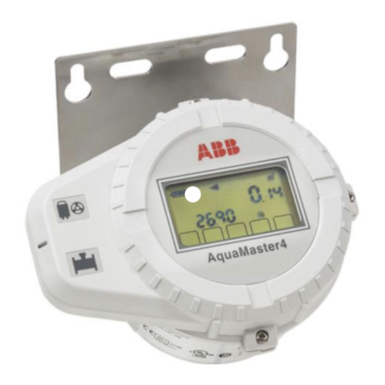
AquaMaster4
Electromagnetic flowmeter flanged sensor
—
Introduction
Harness the power
of electromagnetic
AquaMaster4 flanged sensors are a range of high
flowmeters
performance electromagnetic flowmeter sensors
for the measurement of electrically-conductive
fluids and are normally supplied as factory-
configured, calibrated systems.
This publication provides end-user details for the
AquaMaster4 flanged sensor range.
The ideal flowmeter for potable
water distribution networks,
revenue metering and irrigation
applications
Measurement made easy
For more information
Further publications for AquaMaster4 are available
for free download from
http://new.abb.com/products/measurement-
products
Advertisement
Table of Contents

Related Manuals for ABB AquaMaster4


Summary of Contents for ABB AquaMaster4
- Page 1 Measurement made easy — Introduction For more information Harness the power of electromagnetic AquaMaster4 flanged sensors are a range of high Further publications for AquaMaster4 are available flowmeters performance electromagnetic flowmeter sensors for free download from for the measurement of electrically-conductive http://new.abb.com/products/measurement-...
-
Page 2: Table Of Contents
Fluid level ........11 FEW4 AquaMaster4 sensor – electrical ..5 Pipeline support . - Page 3 A Q U A M A S T E R 4 | E L E C T R O M A G N E T I C F LO W M E T E R F L A N G E D S E N S O R | O I/ F E W 4 0 0/ F R V - E N R E V. A Commissioning .
-
Page 4: Health & Safety
A Q U A M A S T E R 4 | E L E C T R O M A G N E T I C F LO W M E T E R F L A N G E D S E N S O R | O I/ F E W 4 0 0/ F R V - E N R E V. A Health &... -
Page 5: Potential Safety Hazards
Measurement, Control and Laboratory Use’ and complies with ABB is committed to ensuring that the risk of any US NEC 500 and Occupational Safety & Health Administration. environmental damage or pollution caused by any of If the equipment is used in a manner NOT specified by the its products is minimized as far as possible. -
Page 6: Information On Rohs Directive 2011/65/Eu (Rohs Ii)
Product symbols (RoHS II) Symbols that may appear on this product are shown below: ABB, Industrial Automation, Measurement & Analytics, UK, fully supports the objectives of the ROHS II directive. All in-scope Risk of electric shock. products placed on the market by IAMA UK on and following the 22nd of July 2017 and without any specific exemption, will be compliant to the ROHS II directive, 2011/65/EU. -
Page 7: Sensors Overview
A Q U A M A S T E R 4 | E L E C T R O M A G N E T I C F LO W M E T E R F L A N G E D S E N S O R | O I/ F E W 4 0 0/ F R V - E N R E V. A Sensors overview R-series | reduced bore Figure 1 R-series DN40 to DN300... -
Page 8: F-Series | Full Bore
A Q U A M A S T E R 4 | E L E C T R O M A G N E T I C F LO W M E T E R F L A N G E D S E N S O R | O I/ F E W 4 0 0/ F R V - E N R E V. A …... -
Page 9: Product Identification
40m 3/hr Q3/Q1(R): 250 Model type / number Model type / number Sensor-specific tag Sensor-specific tag ABB-defined product serial number ABB-defined product serial number Power supply, m in. / max. voltage rating Enclosure ingress protection rating Logger (shown if available) -
Page 10: Transport And Storage
The ambient conditions for the transport and storage of the • Do not use chains as they may damage the housing. sensor must correspond to the ambient conditions for operation of the sensor. Adhere to the AquaMaster4 data sheet (DS/FET400-EN)! Figure 9 Transport instructions ≤ DN 450... -
Page 11: Installation
A Q U A M A S T E R 4 | E L E C T R O M A G N E T I C F LO W M E T E R F L A N G E D S E N S O R | O I/ F E W 4 0 0/ F R V - E N R E V. A 5 Installation General information Installation requirements... -
Page 12: Pipeline Support
A Q U A M A S T E R 4 | E L E C T R O M A G N E T I C F LO W M E T E R F L A N G E D S E N S O R | O I/ F E W 4 0 0/ F R V - E N R E V. A …5 Installation …Installation requirements Pipeline support... -
Page 13: Flow Direction / Straight Pipe Requirements
A Q U A M A S T E R 4 | E L E C T R O M A G N E T I C F LO W M E T E R F L A N G E D S E N S O R | O I/ F E W 4 0 0/ F R V - E N R E V. A Flow direction / straight pipe requirements F-style sensor: in most installations, a straight upstream Ensure the flow direction in the pipeline corresponds to the... -
Page 14: Localized Heating / Welding
A Q U A M A S T E R 4 | E L E C T R O M A G N E T I C F LO W M E T E R F L A N G E D S E N S O R | O I/ F E W 4 0 0/ F R V - E N R E V. A …5 Installation Localized heating / welding Cable routing... -
Page 15: Burying A Sensor
When burying a sensor, ensure it can be found easily if required (for example, mark the installation position with a post). Installing a protection plate above the meter is also recommended. CAUTION For further advice when burying sensors, contact the ABB Service Organization. Protection Backfill plate recommended Figure 26 Underground installations... -
Page 16: Dimensions
A Q U A M A S T E R 4 | E L E C T R O M A G N E T I C F LO W M E T E R F L A N G E D S E N S O R | O I/ F E W 4 0 0/ F R V - E N R E V. A …5 Installation Dimensions R-style sensor –... - Page 17 A Q U A M A S T E R 4 | E L E C T R O M A G N E T I C F LO W M E T E R F L A N G E D S E N S O R | O I/ F E W 4 0 0/ F R V - E N R E V. A Flange Dimensions in mm (in .) Approx .
-
Page 18: R-Style Sensor - Dn 350 To Dn 600 (14 To 24 In.)
A Q U A M A S T E R 4 | E L E C T R O M A G N E T I C F LO W M E T E R F L A N G E D S E N S O R | O I/ F E W 4 0 0/ F R V - E N R E V. A …5 Installation …Dimensions R-style sensor –... - Page 19 A Q U A M A S T E R 4 | E L E C T R O M A G N E T I C F LO W M E T E R F L A N G E D S E N S O R | O I/ F E W 4 0 0/ F R V - E N R E V. A Flange Dimensions in mm (in .) Approx .
-
Page 20: V-Style Sensor - Dn 40 To Dn 200 (11/2 To 8 In.)
A Q U A M A S T E R 4 | E L E C T R O M A G N E T I C F LO W M E T E R F L A N G E D S E N S O R | O I/ F E W 4 0 0/ F R V - E N R E V. A …5 Installation …Dimensions V-style sensor –... - Page 21 A Q U A M A S T E R 4 | E L E C T R O M A G N E T I C F LO W M E T E R F L A N G E D S E N S O R | O I/ F E W 4 0 0/ F R V - E N R E V. A Flange Dimensions in mm (in .) Approx .
-
Page 22: F-Style Sensor - Dn 250 To Dn 400 (10 To 16 In.)
A Q U A M A S T E R 4 | E L E C T R O M A G N E T I C F LO W M E T E R F L A N G E D S E N S O R | O I/ F E W 4 0 0/ F R V - E N R E V. A …5 Installation …Dimensions F-style sensor –... - Page 23 A Q U A M A S T E R 4 | E L E C T R O M A G N E T I C F LO W M E T E R F L A N G E D S E N S O R | O I/ F E W 4 0 0/ F R V - E N R E V. A Flange Dimensions in mm (in .) Approx .
-
Page 24: F-Style Sensor - Dn 450 To Dn 600 (18 To 24 In.)
A Q U A M A S T E R 4 | E L E C T R O M A G N E T I C F LO W M E T E R F L A N G E D S E N S O R | O I/ F E W 4 0 0/ F R V - E N R E V. A …5 Installation …Dimensions F-style sensor –... - Page 25 A Q U A M A S T E R 4 | E L E C T R O M A G N E T I C F LO W M E T E R F L A N G E D S E N S O R | O I/ F E W 4 0 0/ F R V - E N R E V. A Flange Dimensions in mm (in .) Approx .
-
Page 26: (28 To 96 In.)
A Q U A M A S T E R 4 | E L E C T R O M A G N E T I C F LO W M E T E R F L A N G E D S E N S O R | O I/ F E W 4 0 0/ F R V - E N R E V. A …5 Installation …Dimensions F-style sensor –... - Page 27 A Q U A M A S T E R 4 | E L E C T R O M A G N E T I C F LO W M E T E R F L A N G E D S E N S O R | O I/ F E W 4 0 0/ F R V - E N R E V. A Flange Dimensions in mm (in .) Approx .
- Page 28 A Q U A M A S T E R 4 | E L E C T R O M A G N E T I C F LO W M E T E R F L A N G E D S E N S O R | O I/ F E W 4 0 0/ F R V - E N R E V. A …5 Installation …Dimensions …F-style sensor –...
- Page 29 A Q U A M A S T E R 4 | E L E C T R O M A G N E T I C F LO W M E T E R F L A N G E D S E N S O R | O I/ F E W 4 0 0/ F R V - E N R E V. A Flange Dimensional in mm (in .) Approx .
- Page 30 A Q U A M A S T E R 4 | E L E C T R O M A G N E T I C F LO W M E T E R F L A N G E D S E N S O R | O I/ F E W 4 0 0/ F R V - E N R E V. A …5 Installation …Dimensions …F-style sensor –...
- Page 31 A Q U A M A S T E R 4 | E L E C T R O M A G N E T I C F LO W M E T E R F L A N G E D S E N S O R | O I/ F E W 4 0 0/ F R V - E N R E V. A Flange Dimensional in mm (in .) Approx .
-
Page 32: Grounding
A Q U A M A S T E R 4 | E L E C T R O M A G N E T I C F LO W M E T E R F L A N G E D S E N S O R | O I/ F E W 4 0 0/ F R V - E N R E V. A …5 Installation Grounding The sensor must be cross-bonded to the upstream and... -
Page 33: Connections
A Q U A M A S T E R 4 | E L E C T R O M A G N E T I C F LO W M E T E R F L A N G E D S E N S O R | O I/ F E W 4 0 0/ F R V - E N R E V. A Connections Signal cable connection –... -
Page 34: Commissioning
A Q U A M A S T E R 4 | E L E C T R O M A G N E T I C F LO W M E T E R F L A N G E D S E N S O R | O I/ F E W 4 0 0/ F R V - E N R E V. A 6 Commissioning Repair Safety instruction... -
Page 35: Recycling And Disposal
• If it is not possible to dispose of old equipment properly, ABB Service can take receipt of and dispose of returns. Contact your local ABB Sales or Service representatives for a quotation. -
Page 36: Specification
A Q U A M A S T E R 4 | E L E C T R O M A G N E T I C F LO W M E T E R F L A N G E D S E N S O R | O I/ F E W 4 0 0/ F R V - E N R E V. A 9 Specification Reduced bore sensor Metrological performance to OIML R49... - Page 37 A Q U A M A S T E R 4 | E L E C T R O M A G N E T I C F LO W M E T E R F L A N G E D S E N S O R | O I/ F E W 4 0 0/ F R V - E N R E V. A Bore sizes and flange types Environmental and process conditions Bore size range...
-
Page 38: Full Bore Sensor
A Q U A M A S T E R 4 | E L E C T R O M A G N E T I C F LO W M E T E R F L A N G E D S E N S O R | O I/ F E W 4 0 0/ F R V - E N R E V. A …9 Specification Full bore sensor Metrological performance to OIML R49... - Page 39 A Q U A M A S T E R 4 | E L E C T R O M A G N E T I C F LO W M E T E R F L A N G E D S E N S O R | O I/ F E W 4 0 0/ F R V - E N R E V. A Bore and flange material •...
- Page 40 A Q U A M A S T E R 4 | E L E C T R O M A G N E T I C F LO W M E T E R F L A N G E D S E N S O R | O I/ F E W 4 0 0/ F R V - E N R E V. A …9 Specification …...
-
Page 41: 10 Appendix
A Q U A M A S T E R 4 | E L E C T R O M A G N E T I C F LO W M E T E R F L A N G E D S E N S O R | O I/ F E W 4 0 0/ F R V - E N R E V. A 10 Appendix Declarations of conformity IMPORTANT (NOTE) All documentation, declarations of conformity, and certificates are available in ABB’s download area: www.abb.com/flow. - Page 42 A Q U A M A S T E R 4 | E L E C T R O M A G N E T I C F LO W M E T E R F L A N G E D S E N S O R | O I/ F E W 4 0 0/ F R V - E N R E V. A Acknowledgments •...
- Page 43 A Q U A M A S T E R 4 | E L E C T R O M A G N E T I C F LO W M E T E R F L A N G E D S E N S O R | O I/ F E W 4 0 0/ F R V - E N R E V. A Notes...
- Page 44 We reserve the right to make technical changes or modify the contents of this document without prior notice. With regard to purchase orders, the agreed particulars shall prevail. ABB does not accept any responsibility whatsoever for potential errors or possible lack of information in this document.