ABB AquaMaster4 Operating Instructions Manual
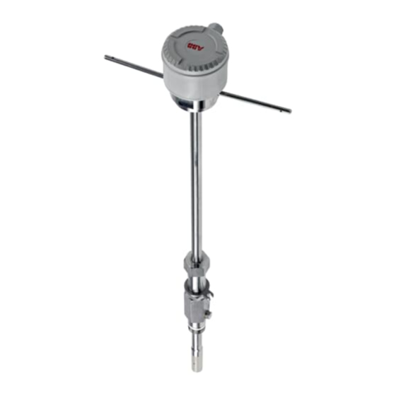
Electromagnetic flowmeter
insertion sensor
Hide thumbs
Also See for AquaMaster4:
- Manual (44 pages) ,
- Manual (40 pages) ,
- Operating instruction (72 pages)
Table of Contents
Advertisement
Quick Links
See also:
Manual
—
A B B M E A S U R E M E N T & A N A LY T I C S | O P E R AT I N G I N S T R U C T I O N
AquaMaster4
Electromagnetic flowmeter
insertion sensor
—
Introduction
Harness the power
of electromagnetic
AquaMaster4 is a range of high performance
flowmeters
electromagnetic flowmeters for the measurement
of electrically-conductive fluids and are normally
supplied as factory-configured, calibrated systems.
This Operating Instruction provides end-user
details for AquaMaster4 insertion sensors.
The ideal flowmeter for potable
water distribution networks, survey
and flow investigation and
irrigation applications
Measurement made easy
For more information
Further publications for AquaMaster4 are available
for free download from:
http://new.abb.com/products/measurement-
products
Advertisement
Table of Contents

Related Manuals for ABB AquaMaster4


Summary of Contents for ABB AquaMaster4
- Page 1 Measurement made easy — Introduction For more information Harness the power of electromagnetic AquaMaster4 is a range of high performance Further publications for AquaMaster4 are available flowmeters electromagnetic flowmeters for the measurement for free download from: of electrically-conductive fluids and are normally http://new.abb.com/products/measurement-...
-
Page 2: Table Of Contents
Extremes of temperature ..... 9 AquaMaster4 insertion sensor – electrical ..4 Seal materials/fluid temperatures ... . 10 Safety standards . - Page 3 A Q U A M A S T E R 4 | E L E C T R O M A G N E T I C F LO W M E T E R I N S E R T I O N S E N S O R | O I/ F E W 4 0 0/A P - E N R E V. B Commissioning .
-
Page 4: Health & Safety
‘IMPORTANT (NOTE)’ does not indicate a dangerous or harmful situation. Potential safety hazards AquaMaster4 insertion sensor – electrical Safety precautions WARNING – BODILY INJURY Be sure to read, understand and follow the instructions To ensure safe use when operating this equipment, the... -
Page 5: Safety Standards
Recycle separately from general waste under the ABB is committed to ensuring that the risk of any WEEE directive. environmental damage or pollution caused by any of... -
Page 6: Insertion Sensor Overview
Safety mechanism – must be engaged, see page 16 Locking collar Insertion sensor valve Process connection (1 in. BSP/1.5 in. BSP/1 in. NPT) Insertion sensor shaft Insertion sensor tip Remote insertion sensor Insertion flowmeter Figure 1 AquaMaster4 insertion sensor overview... -
Page 7: Product Identification
500 MAP: 16 bar Model type/number Model type/number Insertion sensor-specific tag Insertion sensor-specific tag ABB-defined product serial number ABB-defined product serial number Power supply, min./max. voltage rating Enclosure ingress protection rating Logger (shown if available) Insertion sensor size/manifold absolute pressure (psig)/temperature... -
Page 8: Transport And Storage
Storage temperature –20 to 60 °C (–4 to 140 °F) The ambient conditions for the transport and storage of the insertion sensor must correspond to the ambient conditions for operation of the insertion sensor. Adhere to the AquaMaster4 data sheet (DS/FET400-EN)! -
Page 9: Installation
A Q U A M A S T E R 4 | E L E C T R O M A G N E T I C F LO W M E T E R I N S E R T I O N S E N S O R | O I/ F E W 4 0 0/A P - E N R E V. B 5 Installation requirements General information... -
Page 10: Seal Materials/Fluid Temperatures
A Q U A M A S T E R 4 | E L E C T R O M A G N E T I C F LO W M E T E R I N S E R T I O N S E N S O R | O I/ F E W 4 0 0/A P - E N R E V. B …5 Installation Seal materials/fluid temperatures Flow direction... -
Page 11: Cable Routing
A Q U A M A S T E R 4 | E L E C T R O M A G N E T I C F LO W M E T E R I N S E R T I O N S E N S O R | O I/ F E W 4 0 0/A P - E N R E V. B Cable routing Localized heating/welding The insertion sensor must not be submitted to localized... -
Page 12: Dimensions
1.5 in. BSP 1 in. NPT 800, 1000 1200 or 1400 (31.5, 39.4, 47.3 or 55.0) 300, 500 700 or 1000 (11.8, 19.7, 27.6 or 39.4) maximum insertion depth Remote insertion sensor Integral insertion sensor Figure 13 AquaMaster4 A-insertion sensor dimensions... -
Page 13: Setting Up
A Q U A M A S T E R 4 | E L E C T R O M A G N E T I C F LO W M E T E R I N S E R T I O N S E N S O R | O I/ F E W 4 0 0/A P - E N R E V. B Setting up Mean axial velocity method (1/8 Diameter) The basic equation for volume measurement using the... -
Page 14: Measuring The Internal Diameter Of The Pipe
2 Open the valve and push the tool in gently until it touches (performed on ABB's UKAS-approved and traceable flow rigs in the other side of the pipe. -
Page 15: Connections
A Q U A M A S T E R 4 | E L E C T R O M A G N E T I C F LO W M E T E R I N S E R T I O N S E N S O R | O I/ F E W 4 0 0/A P - E N R E V. B Connections •... -
Page 16: Potting The Remote Insertion Sensor Terminal
A Q U A M A S T E R 4 | E L E C T R O M A G N E T I C F LO W M E T E R I N S E R T I O N S E N S O R | O I/ F E W 4 0 0/A P - E N R E V. B …5 Installation Pipeline preparation Potting the remote insertion sensor terminal housing... -
Page 17: Inserting/Removing The Insertion Sensor
A Q U A M A S T E R 4 | E L E C T R O M A G N E T I C F LO W M E T E R I N S E R T I O N S E N S O R | O I/ F E W 4 0 0/A P - E N R E V. B Inserting/Removing the insertion sensor WARNING –... -
Page 18: Setting The Insertion Depth
A Q U A M A S T E R 4 | E L E C T R O M A G N E T I C F LO W M E T E R I N S E R T I O N S E N S O R | O I/ F E W 4 0 0/A P - E N R E V. B …5 Installation Setting the insertion depth Centre line method for pipe diameters ≤1 m (≤40 in) -
Page 19: Centre Line Method For Pipe Diameters >1 M
A Q U A M A S T E R 4 | E L E C T R O M A G N E T I C F LO W M E T E R I N S E R T I O N S E N S O R | O I/ F E W 4 0 0/A P - E N R E V. B Centre line method for pipe diameters >1 m ≤2m (>40 in ≤80 in) WARNING –... -
Page 20: Mean Axial Velocity Method (1/8 Diameter)
A Q U A M A S T E R 4 | E L E C T R O M A G N E T I C F LO W M E T E R I N S E R T I O N S E N S O R | O I/ F E W 4 0 0/A P - E N R E V. B …5 Installation Mean axial velocity method (1/8 Diameter) WARNING –... -
Page 21: Insertion Sensor Alignment
A Q U A M A S T E R 4 | E L E C T R O M A G N E T I C F LO W M E T E R I N S E R T I O N S E N S O R | O I/ F E W 4 0 0/A P - E N R E V. B Insertion sensor alignment WARNING –... -
Page 22: Commissioning
A Q U A M A S T E R 4 | E L E C T R O M A G N E T I C F LO W M E T E R I N S E R T I O N S E N S O R | O I/ F E W 4 0 0/A P - E N R E V. B 6 Commissioning Operation Safety instruction... -
Page 23: Diagnostics
A Q U A M A S T E R 4 | E L E C T R O M A G N E T I C F LO W M E T E R I N S E R T I O N S E N S O R | O I/ F E W 4 0 0/A P - E N R E V. B 8 Diagnostics 9 Maintenance Refer to Instruction manual OI/FET400-EN for insertion sensor... -
Page 24: Spare Parts
• If it is not possible to dispose of old equipment properly, 3KXF208400L2200 AM4 pressure transducer 20 bar 20 m (60 ft. approx) ABB Service can take receipt of and dispose of returns. 3KXF208400L2500 AM4 pressure transducer 40 bar 10 m (30 ft. approx) -
Page 25: Specification
A Q U A M A S T E R 4 | E L E C T R O M A G N E T I C F LO W M E T E R I N S E R T I O N S E N S O R | O I/ F E W 4 0 0/A P - E N R E V. B 12 Specification Mounting Environmental and process conditions... -
Page 26: Appendix
ISO 7145 '(BS 1042) Measurement of fluid flow in closed All documentation, declarations of conformity, and conduits 'Part 2 Velocity area methods' describes methods of certificates are available in ABB's download area: calculating volumetric flow from velocity measurements. www.abb.com/flow. Section 2.2: 1982 'Method of measurement of velocity at one... -
Page 27: Velocity Limitations
A Q U A M A S T E R 4 | E L E C T R O M A G N E T I C F LO W M E T E R I N S E R T I O N S E N S O R | O I/ F E W 4 0 0/A P - E N R E V. B Velocity limitations Velocity profiles background Figure 28 shows a fully-developed turbulent profile of the flow... -
Page 28: Testing The Flow Profile For Symmetry
A Q U A M A S T E R 4 | E L E C T R O M A G N E T I C F LO W M E T E R I N S E R T I O N S E N S O R | O I/ F E W 4 0 0/A P - E N R E V. B …Appendix Velocity profiles background The Point of Mean Velocity is on the knee of the curve (the... -
Page 29: Single Entry Point Method
• if the calculated ratio is not between 0.95 and 1.05, re-site accuracy of reading. To facilitate this ABB have developed the insertion sensor for optimum accuracy. ScrewDriver software for the PC that calculates Fi and Fp for any measured velocity profile – see IM/SDR section 'ABB Flow Profiling'. -
Page 30: Acknowledgments
A Q U A M A S T E R 4 | E L E C T R O M A G N E T I C F LO W M E T E R I N S E R T I O N S E N S O R | O I/ F E W 4 0 0/A P - E N R E V. B Acknowledgments •... - Page 31 A Q U A M A S T E R 4 | E L E C T R O M A G N E T I C F LO W M E T E R I N S E R T I O N S E N S O R | O I/ F E W 4 0 0/A P - E N R E V. B Notes...
- Page 32 We reserve the right to make technical changes or modify the contents of this document without prior notice. With regard to purchase orders, the agreed particulars shall prevail. ABB does not accept any responsibility whatsoever for potential errors or possible lack of information in this document.