Table of Contents
Advertisement
Quick Links
—
A B B M E A S U R E M E N T & A N A LY T I C S | O P E R AT I N G I N S T R U C T I O N | O I/ T B 4 0 4 - E N R E V. B
TB404
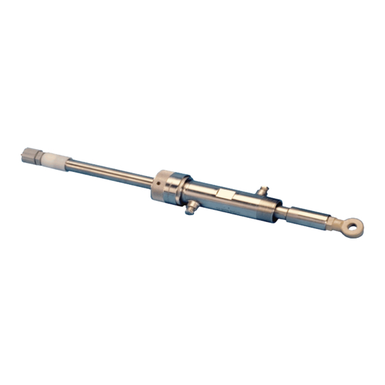
Toroidal conductivity sensors
Introduction
—
TB404 conductivity
sensors
TB404 toroidal conductivity sensors expand the
advancements in process conductivity
measurement initiated by ABB with 4-electrode
conductivity measurement. Unlike 4-electrode
sensors, toroidal sensors have no electrodes.
TB404 – perfect for use in standard
to highly corrosive solutions
Measurement made easy
Advertisement
Table of Contents

Related Manuals for ABB TB404


Summary of Contents for ABB TB404
- Page 1 A B B M E A S U R E M E N T & A N A LY T I C S | O P E R AT I N G I N S T R U C T I O N | O I/ T B 4 0 4 - E N R E V. B TB404 Toroidal conductivity sensors TB404 – perfect for use in standard to highly corrosive solutions Measurement made easy Introduction —...
- Page 2 For more information The Data Sheet for the TB404 toroidal conductivity sensors is available for free download from: www.abb.com/analytical or by scanning this code: Search for or click on: Data sheet DS/TB404-EN TB404 toroidal conductivity sensors...
- Page 3 Trademarks and Registrations Registrations and trademarks used in this document include: ® Mylar Registered trademark of E.I. DuPont de Nemours Company, Incorporated ® Viton Registered trademark of E.I. DuPont de Nemours Company, Incorporated ® Tri-Clamp Registered trademark of Alfa Laval, Incorporated ™...
- Page 4 Preface This publication is for the use of technical personnel responsible for installa- tion of the ABB Type TB404 Toroidal Conductivity Sensor. This instruction contains hardware installation instructions only. Wiring pro- cedures, calibration procedures, etc., are covered in product instructions of instruments compatible with the Type TB404 sensor.
- Page 5 List of Effective Pages Total number of pages in this instruction is 35, consisting of the following: Page No. Change Date Preface Original List of Effective Pages September 11, 2006 iii through vi August 23, 2006 1-1 through 1-6 August 23, 2006 2-1 through 2-3 Original Original...
-
Page 6: Table Of Contents
Table of Contents Page SECTION 1 - INTRODUCTION ....................1-1 OVERVIEW ..............................1-1 INTENDED USER ............................1-1 SENSOR DESCRIPTION ..........................1-1 SENSOR APPLICATION..........................1-1 INSTRUCTION CONTENT ..........................1-2 HOW TO USE THIS INSTRUCTION ......................1-2 REFERENCE DOCUMENTS..........................1-2 NOMENCLATURE ............................1-3 SPECIFICATIONS............................1-4 ACCESSORIES..............................1-6 SECTION 2 - INSTALLATION .....................2-1 INTRODUCTION ............................2-1 UNPACKING AND INSPECTION.........................2-1 LOCATION CONSIDERATIONS ........................2-1 INSTALLATION PROCEDURES ........................2-3... - Page 7 List of Figures (continued) Title Page PR5-2 High Pressure Hot Tap Assembly ......................PR5-3 List of Tables Title Page 1-1. Reference Documents ..........................1-2 1-2. Nomenclature............................1-3 1-3. Specifications............................1-4 1-4. Accessories1 ............................1-6 2-1. Installation Procedures..........................2-3...
- Page 8 Safety Summary SPECIFIC Always use the sensor guide when using the high pressure hot tap WARNINGS assembly. The sensor guide is a tightly toleranced 1½ in.NPT nipple that prevents adverse play between the insertion rod and the sensor guide. Adverse play could damage the insertion rod and injure per- sonnel.
- Page 9 Safety Summary (continued) THIS PAGE INTENTIONALL LEFT BLANK...
-
Page 10: Section 1 - Introduction
Type TB404 sensor. SENSOR DESCRIPTION The Type TB404 sensor employs an encapsulated design that makes it ideal for aggressive and harsh process streams. The analyzers and transmitters for which the sensor was designed measure moderate to high conductivity streams. -
Page 11: How To Use This Instruction
The proce- dures can be removed and placed into separate folders or notebooks and car- ried to the job site. REFERENCE DOCUMENTS Table lists the ABB documents to be used in conjunction with this instruction. Table 1-1. Reference Documents Number Document... -
Page 12: Nomenclature
INTRODUCTION NOMENCLATURE Table lists the nomenclature for the Type TB404 sensor. Table 1-2. Nomenclature Position 9 10 11 12 13 Type T B 4 0 4 Toroidal Conductivity Sensor Sensor Style Next Page ⁄ Standard with -20 threads, PEEK encapsulated Sanitary, 2-in. -
Page 13: Specifications
11 must match the material selected in positions 9 and 10. 5. Stainless steel 1-½-in. full port ball valves are available from ABB. Refer to Table 1-4. 6. An interconnecting cable going from the sensor to the conductivity instrument is available for a per foot charge. Refer to Table 1-4. - Page 14 O-rings per sensor nomenclature Materials 316 stainless steel and Titanium Process connection 1½ in. NPT with ABB supplied ball valve (Titanium ball valve supplied by customer) TB4042 Minimum 0 to 400 μS, maximum 0 to 2,000 mS Range...
-
Page 15: Accessories
INTRODUCTION ACCESSORIES Table lists the accessories available for use with the Type TB404 sen- sors. Table 1-4. Accessories Accessory Description 4TB3004-0008 Interconnecting cable, Teflon®* jacketed, 6-conductor, sensor to conductivity instrument 4TB4711-0021 Retaining nut for in-line flow assembly 4TB4906-0014 Viton gasket for in-line flow assembly ⁄... -
Page 16: Section 2 - Installation
Table 1-3. LOCATION CONSIDERATIONS The Type TB404 sensor employs an encapsulated design that makes it ideal for aggressive and harsh process streams. Sensor variations accommodate submersible installations such as tanks and open vessels or waterways, pipe- lines, and sanitary pipelines and tanks with two-inch tri-clamp fittings. -
Page 17: Type Tb4042 Sensor
INSTALLATION FLA T INDICA TES SENSING AREA ORIENT A TION 15/16-20 THREADS O-RINGS 116.8 4.60 PEEK BOD Y TEMPERA TURE SENSOR LOCA TION SENSING AREA (DONUT) SENSOR BORE DIMENSIONS MILLIMETERS INCHES 36.1 1.42 T00872A Figure 2-1. Type TB4042 Sensor The sensing area must be completely immersed into the fluid (Fig. 2-2). •... -
Page 18: Installation Procedures
INSTALLATION SENSING AREA FLOW FLOW SENSING AREA SENSING AREA P ARALLEL TO FLOW PERPENDICULARTO FLOW FLUID LEVEL FLUID LEVEL FLUID LEVEL BELOW FLUID LEVEL ABOVE Figure 2-2. Sensor Orientation Requirements INSTALLATION PROCEDURES Table lists the installation procedures for the various sensor hardware types. -
Page 19: Section 3 - Repair And Replacement
SECTION 3 - REPAIR AND REPLACEMENT INTRODUCTION This section does not contain repair instructions for the Type TB404 Toroi- dal Conductivity Sensor. Due to the nature of its design, complete sensor replacement is required when it has been damaged or does not properly func- tion. -
Page 20: Section 4 - Support Services
When ordering replacement parts, specify nomenclature type, part name and part number. ABB is ready to assist in the use and repair of its products at any time. Requests for sales and/or application service should be made to the nearest sales or service office. -
Page 21: Submersible Assembly
Place pipe sealant, Teflon®* tape or equivalent onto the ¾ in. NPT male threads of the submersible coupling adapter. NOTE: ABB recommends the application of pipe sealant, Teflon®* tape or equivalent onto all pipe threads to prevent process liquids from seeping into the conduit piping. - Page 22 Attach a section of conduit pipe to the pipe coupling. This section should be long enough to position the sensor in the desired location within the tank, vessel or trough to meet the installation guidelines described in Section USER-SUPPLIED CONDUIT PIPE USER-SUPPLIED COUPLING 3/4-IN.
- Page 23 PROCEDURE PR2 - IN-LINE FLOW ASSEMBLY PURPOSE/SCOPE 20 min. This procedure explains how to install the in-line flow assembly. Parts Number Description 4TB4711-0021 Nut, retaining 4TB4906-0014 In-line gasket, Viton 4TB4951-0085 In-line fitting, 1½-in., 316 stainless steel 4TB4951-0087 In-line fitting, 1½-in., CPVC 4TB4951-0088 In-line fitting, 1½-in., Titanium 4TB5110-0067...
- Page 24 1-1/2-IN. IN-LINE IN-LINE FITTING GASKET TYPE TB404 SENSOR 3/4-IN. NO. 2-117 ADAPTER RET AINING O-RINGS ASSEMBLED IN-LINE SENSOR T00876A Figure PR2-1. In-Line Assembly, Exploded View ⁄ Using the -inch open-end wrench on the wrench flats on the sensor, rotate the sensor so that the sensing area is perpendicular to the flow path to...
- Page 25 9/16-IN. W RENCH 3/4 IN. CONDUIT ADAPTER FLA TS VITON GASKET RET AININGNUT IN-LINE FITTING 1-1/2 IN. NPTTEE SIDE VIEW FRONT VIEW T0087 Figure PR2-2. In-Line Assembly in Pipe or Tank Fitting Install the threaded end of the conduit/cable gland adapter onto the remaining threads on the sensor.
- Page 26 PROCEDURE PR3 - HOT TAP ASSEMBLIES PURPOSE/SCOPE 20 min. This procedure explains how to install the hot tap assemblies. Parts Number Description customer-supplied A/R Pipe sealant, high temperature customer-supplied Receptacle, 1½ in. NPT 4TB9515-0065 Hardware kit for high pressure hot tap assembly with Titanium hardware and EPDM hardware O-rings (Nos.
-
Page 27: Low Pressure Hot Tap Assemblies
SAFETY CONSIDERATIONS 1. Always use the sensor guide when using the high pressure hot tap assembly. The sensor guide is a tightly toleranced 1½ in. NPT nipple that prevents adverse play between the insertion rod and the sensor guide. Adverse play could damage the insertion rod and injure personnel. - Page 28 1. Temporarily insert the sensor assembly into the process receptacle. Example: 2. Set the insertion rod to the proper depth and orientation according to the installation guidelines described in Section 2 or measure the distance from the end of the process receptacle to the desired sensor location. 3.
- Page 29 HAND-TIGHT 1/4-IN. FLUSHING COMPRESSION PORTS (2 TYP) FITTING 1-1/2-IN. NIPPLE INSERTION ROD OUTMOST COMPRESSION NUT 1-1/2-IN. TEE 1-1/2-IN. FULL INNERMOST COMPRESSION NUT PORT BALL VALVE HAND-TIGHT COMPRESSION FITTING HARDW ARE WRENCH-TIGHT COMPRESSION FITTING 1-1/2-IN. NPT THREAD INSERTION ROD RETRACTED INSERTION ROD EXTENDED WRENCH-TIGHT COMPRESSION FITTING HARDW ARE T00877A Figure PR3-1.
- Page 30 1/4 IN. FLUSHING PORT INSERTION ROD ASSEMBL Y 1/2 IN. NPT ELBOW FOR EXTRACTION END CAP CONDUIT CONNECTION 1-1/2 IN. HOUSING 1-1/2 IN. FULL SENSOR PORT BALL VALVE GUIDE INSERTION ROD RETRACTED INSERTION ROD EXTENDED T00878A Figure PR3-2. High Pressure Hot Tap Assembly PROCEDURE PR3 - 5...
- Page 31 PROCEDURE PR4 - TWO-INCH SANITARY TRI-CLAMP ASSEMBLY PURPOSE/SCOPE 20 min. This procedure explains how to install the two-inch sanitary tri-clamp assembly Parts Number Description customer-supplied Gasket, sanitary customer-supplied Tri-clamp tee, sanitary, 2 in. customer-supplied Tri-clamp, sanitary customer-supplied Conduit/cable gland adapter, ½ in. customer-supplied Conduit, flexible, ½...
- Page 32 TB4043 SENSOR 85.1 3.35 SANIT AR Y GASKET SUPPLIED BY O THERS 2 IN. SANIT ARY DIMENSIONS TRI-CLAMP TEE MILLIMETERS INCHES T00879A Figure PR4-1. Sanitary In-Line Flow Assembly Clamp the sensor to the two-inch sanitary tri-clamp tee using the sani- tary tri-clamp, being sure to maintain the sensor orientation (Fig.
- Page 33 PROCEDURE PR5 - REMOVING SENSOR FROM HOT TAP ASSEMBLIES PURPOSE/SCOPE 5 min. This procedure explains how to remove the sensor from hot tap assemblies. Parts Number Description 4TB8006-0025 Silicone grease 4TB8006-0045 Anti-seize compound Customer-supplied Pipe sealant A/R = as required Tools None SAFETY CONSIDERATIONS...
- Page 34 HAND-TIGHT 1/4-IN. FLUSHING COMPRESSION PORTS (2 TYP) FITTING 1-1/2-IN. NIPPLE INSERTION ROD OUTMOST COMPRESSION NUT 1-1/2-IN. TEE 1-1/2-IN. FULL INNERMOST COMPRESSION NUT PORT BALL VAL VE HAND-TIGHT COMPRESSION FITTING HARDW ARE WRENCH-TIGHT COMPRESSION FITTING 1-1/2-IN. NPT THREAD INSERTION ROD RETRACTED INSERTION ROD EXTENDED WRENCH-TIGHT COMPRESSION FITTING HARDW ARE T00877A...
- Page 35 1/4 IN. FLUSHING PORT INSERTION ROD ASSEMBL Y 1/2 IN. NPT ELBOW FOR EXTRACTION END CAP CONDUIT CONNECTION 1-1/2 IN. HOUSING 1-1/2 IN. FULL SENSOR PORT BALL VALVE GUIDE INSERTION ROD RETRACTED INSERTION ROD EXTENDED T00878A Figure PR5-2. High Pressure Hot Tap Assembly Service the sensor as required.
- Page 36 Solvents are flammable - do not use near extreme heat or open flame. PROCEDURE ABB toroidal conductivity sensors are cleaned using one or a combination of methods. These are recommendations and may not be suitable for all appli- cations. When cleaning, observe all safety precautions required for handling chemicals.
- Page 37 Acid Dip This method removes scales caused by hard water. Verify that any process fluid on the sensor is not incompatible with HCl. Put on gloves, eye protection, safety shields and other protective items as needed for protection. Dip the donut portion of the sensor into a one percent to five percent solution of HCl until this region is free of the unwanted coating.
- Page 38 Index Accessories ..............1-6 Nomenclature..............1-3 Application ..............1-1 Orientation requirements ..........2-3 Cleaning the sensor ..........PR6-1 Parts, spare and replacement........4-1 Hot tap assembly Installation............PR3-1 Removing sensor from........PR5-1 Reference documents..........1-2 How to use this instruction ......... 1-2 Replacement parts............4-1 In-line flow assembly installation ......
- Page 39 Sales Service...
- Page 40 We reserve the right to make technical changes or modify the contents of this document without prior notice. With regard to purchase orders, the agreed particulars shall prevail. ABB does not accept any responsibility whatsoever for potential errors or possible lack of information in this document.