Table of Contents
Advertisement
Quick Links
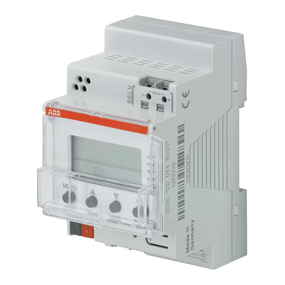
HS/S4.2.1
Brightness sensor
2CDG120044R0011
Installation and
operating instructions
D GB
F
I
S
NL
C1
C5
C2
C6
C3
C7
C4
C8
DA
TA
Sensorwerte
L1 Sensor Ost
528 lx
L2 Sensor Süd
505 lx
L3 Sensor West
883 lx
MENU
OK
Set Phys Adr
2
0,5mm -
L
N
110-240V~
2
2,5mm
50-60Hz
HS/S4.2.1
µ
µ
4
5
10
11
6
12
C2
C4
309597 01
GB
L
N
Advertisement
Table of Contents

Related Manuals for ABB HS/S4.2.1


Summary of Contents for ABB HS/S4.2.1
-
Page 1: Operating Instructions
309597 01 HS/S4.2.1 Brightness sensor 2CDG120044R0011 Installation and operating instructions Sensorwerte L1 Sensor Ost 528 lx L2 Sensor Süd 505 lx D GB L3 Sensor West 883 lx MENU Set Phys Adr 0,5mm - 110-240V~ 2,5mm 50-60Hz HS/S4.2.1 µ µ... -
Page 2: Table Of Contents
Contents Basic safety instructions Display and keys Connection/installation Bus connection, programming physical address Start-up 7 Home page – Sensor values Enter PIN Menu – Settings.. Language.. Display.. System.. Sensors.. Deactivate active sensor Allocate new serial number to active sensor Menu – Switching channels.. Select light threshold (brightness) Select delay Technical date... -
Page 3: Basic Safety Instructions
Basic safety instructions WARNING Danger of death through electric shock or fire! Installation should only be carried out by a professional electrician! • The device is designed for installation on DIN top hat rails (in accordance with EN 60715); device conforms with EN 60669-1 •... -
Page 4: Display And Keys
Screen and keys Connection/installation Screen display, Sensorwerte L1 Sensor Ost e. g. sensor values 528 lx L2 Sensor Süd 505 lx L3 Sensor West 883 lx ? MENU MENU Data – Activate screen – Open menu Set Phys Adr – Cancel menu ... -
Page 5: Connection/Installation
Connection/installation WARNING Danger of death through electric shock! Must only be installed by professional electrician! Disconnect power source! Cover or shield any adjacent live components. Ensure device cannot be switched again! 45° cable Check power supply is disconnected! Spring terminal ... -
Page 6: Bus Connection, Programming Physical Address
Bus connection Program physical address Insert bus line in the front of the device. Press button on front of the device. Ensure correct polarity. à The programming LED lights up. à Device is in program mode. MENU Start-up, diagnostics and configuration are Set Phys Adr Push button... -
Page 7: Start-Up
Start-up The pages displayed depends on the programming by the ETS. Please refer to the Product Handbook for detailed functional descriptions (at www.abb.com/knx). Home page – Sensor values Sensor values If an external sensor is connected, the sensor value (lux value) No sensors appears on screen. -
Page 8: Menu - Settings
Menu – Settings.. Menu Settings .. K1 :Switching channel 1.. K2 :Switching channel 2.. The Settings menu item can be used for setting the language, K3 :Switching channel 3.. K4 :Switching channel 4.. Back screen lighting or information on the device and sensors. MENU Press MENU button. -
Page 9: Language
Settings– Set language Language Use to select language. Deutsch English Francais Press OK to confirm. Espanol Italiano Use to select desired language. Nederlands MENU Settings– Set display Display Use to select display. Light keypress Press OK to confirm. Back MENU... -
Page 10: System
Settings – System.. System Use to select system. Prog. mode 15.15.255 VI.0 Press OK to confirm. SN: 0048112233445566 11.11.2011 MENU The display shows Prog. mode (Programming mode) PA (Physical address) SW (Software version) SN (Serial number) FD (Finishing date) HW (Hardware) -
Page 11: Sensors
Settings – Sensors.. Use to select sensors. Process sensors L1 sensor 1 SN: 123456789 Confirm by pressing OK. L2 sensor 2 inactive L3 sensor 3 Error Back The Sensors menu item can be used to display the lux values MENU for up to 3 connected sensors. -
Page 12: Allocate New Serial Number To Active Sensor
Allocate new serial number to inactive sensor Use to select Next serial number. L1 sensor 1 inactive Press OK to confirm. Next serial number Allocate Back The inactive sensor displays a new SN number. MENU Use to select Allocate. Press OK to confirm and, if reqd., select Back to leave menu. -
Page 13: Menu - Switching Channels
Menu – Switching channels.. Menu Settings .. K1 :Switching channel 1.. K2 :Switching channel 2.. The Switching channels menu item displays the status of the K3 :Switching channel 3.. K4 :Switching channel 4.. Back channel (ON, OFF, disabled/invalid): MENU Press MENU button. ... -
Page 14: Select Light Threshold (Brightness)
Select light thresholds (brightness) The Light thresholds menu item can be used to set of the K1 :Switching channel 1.. Status: brightness of the relevant channel: Light thresholds.. Next channel Back.. to select Light thresholds. MENU Press OK to confirm. ... -
Page 15: Select Delay
Select delay The Delay menu item can be used to set the delay time: K1 :Delay Exceed 15 s Underrun 90 s to select Delay. Back.. Press OK to confirm. MENU to select Exceed or Underrun. Press OK to confirm selection. ... -
Page 16: Technical Data
• Protection class: II subject to correct installation Service address • Protection rating: IP 20 in accordance with EN 60529 ABB STOTZ-KONTAKT GmbH • Pollution level: Eppelheimer Straße 82 69123 Heidelberg • Max. cable cross section: 2.5 mm Germany • Operating voltage KNX: bus voltage ≤10 mA Tel.