Table of Contents
Advertisement
Quick Links
2CKA001473B9679
17.12.2018
│
Product manual
ClimaECO sensors
ABB i-bus
KNX
®
SBS/Ux.0.1x-xx Room temperature controller with xgang
operating function
SBR/Ux.0.1x-xx Room temperature controller with xgang
operating function
SBC/Ux.0.1x-xx Room temperature controller with
CO2/moisture sensor and 6gang operating function
SB/Ux.0.1x-xx Control element xgang
Advertisement
Table of Contents

Related Manuals for ABB ClimaECO SBS/Ux.0.1 Series


Summary of Contents for ABB ClimaECO SBS/Ux.0.1 Series
- Page 1 2CKA001473B9679 17.12.2018 │ Product manual ClimaECO sensors ABB i-bus ® SBS/Ux.0.1x-xx Room temperature controller with xgang operating function SBR/Ux.0.1x-xx Room temperature controller with xgang operating function SBC/Ux.0.1x-xx Room temperature controller with CO2/moisture sensor and 6gang operating function SB/Ux.0.1x-xx Control element xgang...
-
Page 2: Table Of Contents
Table of contents Table of contents Notes on the instruction manual ....................... 17 Safety ............................... 18 Information and symbols used ...................... 18 Intended use ..........................19 Improper use ..........................19 Target group / Qualifications of personnel ..................20 2.4.1 Operation ............................20 2.4.2 Installation, commissioning and maintenance ................20 Safety instructions ......................... - Page 3 Table of contents 7.1.4 Selecting the application program ....................50 7.1.5 Differentiating the application program ..................50 Updating options ............................51 Operation ..............................52 Control elements ........................... 53 Colour concept ..........................54 Operating modes........................... 55 Display overview ........................... 56 9.4.1 Switching On and Off ........................57 9.4.2 Adjust temperature .........................58 9.4.3...
- Page 4 Table of contents 11.1.4.13 Display backlighting white ................78 11.1.4.14 Display backlighting day .................79 11.1.4.15 Display backlighting night ................79 11.1.4.16 Display backlighting red .................80 11.2 Application "Primary function" ....................... 81 11.2.1 Primary function - Application ......................81 11.2.1.1 Object type......................82 11.2.1.2 Reaction on rising edge ..................83 11.2.1.3 Reaction on falling edge .................84 11.2.1.4...
- Page 5 Table of contents 11.4.38 Cooling control — Cooling type ....................105 11.4.39 Cooling control — P-component (x 0.1°C) .................. 105 11.4.40 Cooling control — I-component (min.) ..................106 11.4.41 Cooling control — Extended settings ..................106 11.4.42 Basic stage cooling ........................107 11.4.43 Basic stage cooling —...
- Page 6 Table of contents 11.4.4 Setpoint settings — Cyclic sending of the current set-point temperature (min) ......124 11.4.5 Setpoint settings - Basic set value is ................... 125 11.4.6 Setpoint adjustment ........................126 11.4.7 Setpoint adjustment — Maximum manual increase during heating mode (0 - 9°C) ....126 11.4.8 Setpoint adjustment —...
- Page 7 Table of contents 11.4.2 Fan coil settings - Fan speed levels .................... 142 11.4.3 Fan coil settings - Fan speed levels — Number of fan speed levels .......... 142 11.4.4 Fan coil settings - Fan speed levels — Format of the level output ..........142 11.4.5 Fan coil settings - Fan speed levels —...
- Page 8 Table of contents 11.5.28 Settings — Value for output format switching command ............165 11.5.29 Settings — Value for output format priority ................. 165 11.5.30 Settings — Value for output format switching command ............165 11.5.31 Settings — Value for output format byte ..................166 11.5.32 Settings —...
- Page 9 Table of contents 11.6.28 Step controller — Switch command above threshold 2 .............. 191 11.6.29 Step controller— Priority above threshold 2 ................191 11.6.30 Step controller — Percent above threshold 2 ................192 11.6.31 Step controller — Value above threshold 2 (byte) ..............192 11.6.32 Step controller —...
- Page 10 Table of contents 11.7.4 Application - 2-button dimming ....................213 11.7.4.1 Duration of long operation ................213 11.7.4.2 Manner of dimming ..................214 11.7.4.3 Step size for step-wise dimming (%) ............215 11.7.4.4 Dimming function ..................216 11.7.4.5 Working mode of the buttons for switching ..........217 11.7.4.6 Working mode of the buttons for dimming ..........
- Page 11 Table of contents 11.7.12.2 Light scene memory function ..............249 11.7.12.3 Number of light scene.................. 249 11.7.13 Application - 2-button step switch ....................250 11.7.13.1 Number of objects ..................250 11.7.13.2 Evaluation period ..................251 11.7.13.3 Working mode of the buttons ..............251 11.7.13.4 Sending of objects ..................
- Page 12 Table of contents 11.7.20.9 Colour for Zone 3 ..................283 11.7.20.10 Threshold between Zone 3 and 4 (%) ............283 11.7.20.11 Colour for Zone 4 (up to 99%) ..............284 11.7.20.12 Colour for Zone 5 (corresponds to 100%) ........... 285 11.7.20.13 Colour of function illumination ..............
- Page 13 Table of contents 11.9.6 Application - Staircase lighting ....................313 11.9.6.1 Channel name ..................... 313 11.9.6.2 Object type/number ..................314 11.9.6.3 Switch-off delay ................... 314 11.9.6.4 Retriggering ....................315 11.9.6.5 Switch-off pre-warning ................. 315 11.9.6.6 Time for switch-off pre-warning (s) .............. 316 11.9.6.7 Value for switch-off prewarning (%) ............
- Page 14 Table of contents 12.1.10 LED - Day/Night mode ........................ 333 12.1.11 EF - Enable ..........................334 12.1.12 EF - Automatic switchover time ....................334 12.1.13 HB - In operation ......................... 335 12.1.14 PF - Switching ..........................336 12.1.15 RTC — Status control value of basic heating stage ..............337 12.1.16 RTC —...
- Page 15 Table of contents 12.1.62 RTC — Setpoint error ........................355 12.1.63 RTC: Limit temperature basic heating stage ................355 12.1.64 RTC - Limit temperature additional heating stage ..............355 12.1.65 RTC - Limit temperature basic cooling stage ................355 12.1.66 RTC - Limit temperature additional cooling stage ...............
- Page 16 Table of contents 12.1.114 2-button blind — Adjustment/slats position ................. 370 12.1.115 2-button value transmitter - Switching ..................370 12.1.116 2-button value dimming sensor - Value ..................370 12.1.117 2-button step switch - Switching step x ..................371 12.1.118 LED function - Status LED ......................372 12.1.119 LED function - Scene storage .....................
-
Page 17: Notes On The Instruction Manual
If you pass the device on, also pass on this manual along with it. ABB accepts no liability for any failure to observe the instructions in this manual. If you require additional information or have questions about the device, please contact ABB or visit our Internet site at: www.BUSCH-JAEGER.com... -
Page 18: Safety
However, residual hazards remain. Read and adhere to the safety instructions to prevent hazards of this kind. ABB accepts no liability for any failure to observe the safety instructions. Information and symbols used The following Instructions point to particular hazards involved in the use of the device or provide... -
Page 19: Intended Use
Each use not listed in Chapter 2.2 “Intended use“ on page 19 is deemed improper use and can lead to personal injury and damage to property. ABB is not liable for damages caused by use deemed contrary to the intended use of the device. The associated risk is borne exclusively by the user/operator. -
Page 20: Target Group / Qualifications Of Personnel
Safety Target group / Qualifications of personnel 2.4.1 Operation No special qualifications are needed to operate the device. 2.4.2 Installation, commissioning and maintenance Installation, commissioning and maintenance of the device must only be carried out by trained and properly qualified electrical installers. The electrical installer must have read and understood the manual and follow the instructions provided. -
Page 21: Safety Instructions
Safety Safety instructions Danger - Electric voltage! Electric voltage! Risk of death and fire due to electric voltage of 100 … 240 V. Dangerous currents flow through the body when coming into direct or indirect contact with live components. This can result in electric shock, burns or even death. - Page 22 Safety Caution! - Risk of damaging the device due to external factors! Moisture and contamination can damage the device. Protect the device against humidity, dirt and damage during transport, ■ storage and operation. Product manual 2CKA001473B9679 │22...
-
Page 23: Information On Protection Of The Environment
Information on protection of the environment Information on protection of the environment Environment Consider the protection of the environment! Used electric and electronic devices must not be disposed of with domestic waste. – The device contains valuable raw materials which can be recycled. Therefore, dispose of the device at the appropriate collecting depot. -
Page 24: Setup And Function
Setup and function Setup and function The device is designed for decentralised surface-mounted and flush-mounted installation. ■ The device can be linked with an available actuator via KNX group addresses. ■ The device (with bus coupler) can be assigned to an available switch actuator. ■... -
Page 25: Device Versions
Setup and function Device versions The ClimaECO sensors are available in the following models: – 10gang with display, with/without CO2 and moisture sensor – 6gang with display, with/without CO2 and moisture sensor – Control element 12gang – Control element 8gang °C °C °C... -
Page 26: Device Overview
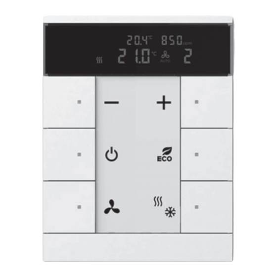
[2] Control element 12gang/RTC with control element 10gang (firmly installed unit), with/without CO2 and humidity sensor [3] Control element 8gang/RTC with control element 6gang (firmly installed unit), with/without CO2 and humidity sensor Abb. 3: Overview of function elements [1] Control buttons [2] Cover/labelling field... - Page 27 Setup and function Display (only RTC devices) ° C ° F ° C ° F Auto Fig. 4: Overview of display Icons of the room temperature control Building protection Local operation is blocked Dew point alarm Standby mode ECO mode Actual temperature 18,5°C Relative humidity / CO2...
-
Page 28: Control Elements
Setup and function Control elements The control element is available in models 6-, 8,- 10- and 12gang. – Various functions can be implemented via the ETS commissioning software. The functions depend on the parameters selected via the respective software application. Fig. -
Page 29: Functions
Setup and function Functions The following table provides an overview of the possible functions and applications of the device: Function (only with devices with display and Special features integrated room temperature controller) – Freely configurable multifunction control – Room temperature controller element –... -
Page 30: Support Rings
[1] VDE Germany [2] Switzerland / British standard (BS) (The support ring for Switzerland is supplied without earth terminal) (The support ring is enclosed with the ABB version) Scope of supply Included in the scope of delivery are: Support ring ■... -
Page 31: Technical Data
Technical data Technical data Technical data Designation Value Power supply: 24 V DC (via the bus line); Bus subscribers ClimaECO sensors: – Without CO sensor: 1 (12 mA) – With CO sensor: 2 (24 mA) Connection Bus connection terminal: 0.4 - 0.8 mm ■... -
Page 32: Dimensional Drawings
Technical data Dimensional drawings 30,7 13,5 90,1 90,1 90,1 90,1 Fig. 8: Dimensions (all dimensions are in mm) Factory settings Product manual 2CKA001473B9679 │32... -
Page 33: Connection, Installation / Mounting
Connection, installation / mounting Connection, installation / mounting Danger - Electric voltage! Risk of death due to electrical voltage of 100 … 240 V during short-circuit in the low-voltage conduit. – Low-voltage and 100 … 240 V conduits must not be installed together in a flush-mounted box! Requirements for the electrician Danger - Electric voltage! -
Page 34: Installation Site
Connection, installation / mounting Installation site For proper commissioning please observe the following points: The device should be installed at a ■ height of approximately 150 cm from the floor and 50 cm from a door frame. 50 cm 150 cm Fig. - Page 35 Connection, installation / mounting This also applies to installation on an ■ exterior wall. – Low outside temperatures have an effect on temperature regulation. Fig. 13: Installation site - Exterior wall Wetting the room temperature ■ controller with fluids is to be avoided. Fig.
-
Page 36: Mounting / Dismantling
Connection, installation / mounting Mounting / dismantling Caution! The device can sustain damage when coming into contact with hard objects! The plastic parts of the device are sensitive. – Pull the attachment off only with your hands. – Do not lever parts off with screwdrivers or similar hard objects. Attention! - Risk of damaging the device Risk of malfunction due to construction dust –... -
Page 37: Electrical Connection
Connection, installation / mounting Electrical connection Carry out the electrical connection according to the circuit diagram. 24 V DC Fig. 16: Connection of bus coupler Product manual 2CKA001473B9679 │37... -
Page 38: Mounting
Connection, installation / mounting Mounting 6.5.1 Flush-mounted installation 6.5.1.1 Removal protection (optional) Notice – After mounting with removal protection, dismantling, see chapter “Dismantling with the removal protection tool“ on page 42, is then only possible with the removal tool! – The removal protection is not a component part of the device and is to be ordered separately. -
Page 39: Mounting/Installation In Flush-Mounted Installation Box
To install the device, perform the following steps: 1. Installing the support ring. Fig. 18: Installation of the support ring Notice ABB version: The scope of delivery also includes two M4 screws, which serve for fixing the Chinese support ring. Product manual 2CKA001473B9679 │39... - Page 40 Connection, installation / mounting 2. Pull the bus line out of the flush- mounted box and connect the line to the bus connection terminal [1], see chapter “Electrical connection“ on page 37. – Check that the polarity is correct! Fig. 19: Connection of the bus line Product manual 2CKA001473B9679 │40...
- Page 41 Connection, installation / mounting 3. Installing the device. – Snap the device into the support ring by hand. Fig. 20: Mounting devices 4. To commission the device, see chapter “Commissioning“ on page ■ Programming is carried out via the programming button [2] on the front of the device.
-
Page 42: Dismantling
Connection, installation / mounting 6.5.2 Dismantling 6.5.2.1 Dismantling with the removal protection tool Notice After mounting with removal protection, see chapter “Removal protection (optional)“ on page 38, dismantling is then only possible with the removal tool! If installed, carry out the following step to dismantle the removal protection: 1. -
Page 43: Surface-Mounted Installation
Connection, installation / mounting 6.5.3 Surface-mounted installation 6.5.3.1 Mounting with surface-mounted mounting frame Notice Surface-mounted housings/frames are not included in the scope of delivery and must be purchased separately! Preparatory work: For the installation on a surface-mounted frame, the fastening screw must be made accessible on the operating section on the front of the device. - Page 44 Connection, installation / mounting Bus cable guide of surface-mounted frame For an alternative cable guide, via the top or bottom side of the frame, a 6 mm borehole can be provided. Notice A centring mark is available on the top and bottom side of the frame for an alternative cable guide.
- Page 45 Connection, installation / mounting Installing the surface-mounted frame Notice The surface-mounted frame can also be screwed to the wall via the flush- mounted box via the different housing recesses. – Do not use countersunk head screws for mounting! Attention! Risk of faulty measurements! –...
- Page 46 Connection, installation / mounting Notice – The mark [4] on the surface-mounted frame "Top" must always point upwards. – Do not use countersunk head screws for mounting the surface-mounted frame. – [A] A flush-mounted box must not project from the wall, otherwise the device cannot be mounted flush on the wall.
- Page 47 Connection, installation / mounting Mounting control elements Fig. 26: Mounting control elements 6. Connect the bus cable [2] with the bus terminal [3] and plug it onto the control element [4]. 7. Hang the control element [4] into the surface-mounted frame [1] from the top. Both openings for hanging must be placed onto the two hooks [A].
-
Page 48: Labelling Inlay
Connection, installation / mounting 6.5.4 Labelling inlay Depending on the device model, carry out the following steps to change the labelling inlay. Fig. 27: Labelling inlay Product manual 2CKA001473B9679 │48... -
Page 49: Commissioning
Commissioning Commissioning Software To start the device a physical address must be assigned first. The physical address is assigned and the parameters are set with the Engineering Tool Software (ETS). NOTE The devices are products of the KNX system and meet KNX guidelines. Detailed expert knowledge by means of KNX training sessions for a better understanding is assumed. -
Page 50: Assigning The Group Address(Es)
Commissioning 7.1.3 Assigning the group address(es) The group addresses are assigned in connection with the ETS. 7.1.4 Selecting the application program Please contact our Internet support unit (www.BUSCH-JAEGER.com). The application is loaded into the device via the ETS. 7.1.5 Differentiating the application program Various functions can be implemented via the ETS. -
Page 51: Updating Options
Updating options Updating options A firmware update is carried out via the KNX bus by means of the ETS app "KNX Bus Update". NOTE The description of the update process can be downloaded via the electronic catalogue (www.busch-jaeger-catalogue.com). It is stored on the device page under category "Software". -
Page 52: Operation
Operation Operation Notice – All devices with room temperature controllers are correspondingly preconfigured in the RTC section and directly access the functions of the internal RTC. – The push-buttons of the device can be individually configured by the installer according to requirement or wishes. –... -
Page 53: Control Elements
Operation Control elements Notice – All devices with room temperature controllers are correspondingly preconfigured in the RTC section and directly access the functions of the internal RTC. – Depending on the model, push-buttons are also located above the device, and can be freely configured. –... -
Page 54: Colour Concept
Operation Colour concept The KNX functions are supported by an LED colour concept. Colour Meaning Yellow Lights Blue Blind control Orange Room temperature control Magenta Light scenes White Neutral / no assignment of functions Red/green Standard illumination Table 4: LED colour concept Notice The operating buttons serve as status and function illumination. -
Page 55: Operating Modes
Operation Operating modes The devices with RTC have the following operating modes: Display Operating mode Comfort operation Application: °C – You are in the room for a longer period of time; the comfort temperature is to be reached. °C Behaviour of the RTC: –... -
Page 56: Display Overview
Operation Display overview °C °F °C °F Auto Fig. 30: Display Display Function Action of the device Controller °C switched on / display of set- °C point temperature °C Display of the actual temperature Heating/cooling is at the normal level. Comfort mode –... -
Page 57: Switching On And Off
Operation 9.4.1 Switching On and Off Notice – The device operates in frost/heat protection mode when switched off. – The following illustration shows an example of a configuration. – The function can be individually parameterized on one of the buttons. 1. -
Page 58: Adjust Temperature
Operation 9.4.2 Adjust temperature Notice – The set-point temperature appears automatically on the display. The device must be switched on for this to happen. – The following illustration shows an example of a configuration. – The function can be individually parameterized on one of the button pairs. The setpoint temperature is adjusted with °C the buttons [1] and [6]. -
Page 59: Adjusting The Fan Speed Levels
Operation 9.4.3 Adjusting the fan speed levels Notice – The following illustration shows an example of a configuration. – The function can be individually parameterized on one of the buttons. 1. Press button [4] to set the desired fan speed level. °C °C Au to... -
Page 60: Eco Mode
Operation 9.4.4 Eco mode ECO mode is used to reduce the room temperature automatically and to reduce the fan speed level, if this option has been parameterized. As a result, less energy is consumed when the occupants are absent, for example. Notice –... -
Page 61: Changing The Operating Status (Heating/Cooling)
Operation 9.4.5 Changing the operating status (heating/cooling) Notice – The following illustration shows an example of a configuration. – The function can be individually parameterized on one of the buttons. 1. Press button [3] to set the desired operating status. °C °C Au to... -
Page 62: Maintenance
Maintenance Maintenance 10.1 Cleaning Caution! - Risk of damaging the device! When spraying on cleaning agents, these can enter the device through ■ crevices. – Do not spray cleaning agents directly onto the device. Aggressive cleaning agents can damage the surface of the device. ■... -
Page 63: Description Of Application And Parameters
Description of application and parameters Description of application and parameters 11.1 Application "Device settings" 11.1.1 Device enable - Application Options: Inactive Enable application Inactive: ■ – Application is not active. Enable application: ■ – Application is active. If the application is activated the device can be blocked temporarily via the 1- bit communication object "EF: enable". -
Page 64: Use Of Automatic Enable/Blockage
Description of application and parameters Application "Device settings" Options: Blocked Enabled Blocked: ■ – The enable object has value"1" after bus voltage recovery. Enabled: ■ – The enable object has value "0" after bus voltage recovery. The parameter serves to ensure that a defined behaviour is present on communication object "EF: enable"... -
Page 65: Use Object For Switchover Time
Description of application and parameters Application "Device settings" 11.1.1.5 Use object for switchover time Options: ■ – The communication object is not enabled. Yes: ■ – The communication object is enabled. A 2-byte communication object "EF: automatic switchover time" can be enabled with this parameter. -
Page 66: Overwrite Switchover Time At Download
Description of application and parameters Application "Device settings" 11.1.1.6 Overwrite switchover time at download Options: ■ – The switchover time is not overwritten during a download of the application. Yes: ■ – The switchover time is overwritten during a download of the application. The parameter can be used to specify whether the data changed via communication object "EF: automatic switchover time"... -
Page 67: Brightness Of The Led During Blockage
Description of application and parameters Application "Device settings" 11.1.1.7 Brightness of the LED during blockage Options: Dark Bright Off: ■ – The LED does not light up at blockage. Dark: ■ – The LED lights up dark at blockage. Bright: ■... -
Page 68: Led Colour In A Blocked State
Description of application and parameters Application "Device settings" 11.1.1.8 LED colour in a blocked state Options: Yellow Orange Violet Blue Green White Yellow - white: ■ – The LED lights up in the specified colour during blockage. The parameter is used to specify the colour the LED lights up in when the device is blocked. Note The parameter is only adjustable if the "Brightness of LED during blockage"... -
Page 69: Day/Night Mode
Description of application and parameters Application "Device settings" 11.1.2.1 Day/Night mode Options: Deactivated Activated Deactivated: ■ – Communication object "LED: day/night mode" is not enabled. Activated: ■ – Communication object "LED: day/night mode" is enabled. If a telegram with value "1" (day) is received via the object, the LED lights up brightly. If a telegram with value "0"... -
Page 70: Alarm Function
Description of application and parameters Application "Device settings" 11.1.2.2 Alarm function Options: Deactivated Activated Options: Yellow Orange Violet Blue Green White Deactivated: ■ – Communication object "LED: Alarm" is not enabled. Activated: ■ – Communication object "LED: Alarm" is enabled. The LED will flash if an ON telegram is received on the 1-bit communication object "Alarm". -
Page 71: Led Brightness During Alarm
Description of application and parameters Application "Device settings" 11.1.2.3 LED brightness during alarm Options: Dark Bright Dark: ■ – The LED lights up dark. Bright: ■ – The LED lights up bright. The parameter is used to specify the brightness the LED lights up in during an alarm Notice This parameter can only be set if the "Alarm function"... -
Page 72: Led Colour During Alarm
Description of application and parameters Application "Device settings" 11.1.2.4 LED colour during alarm Options: Yellow Orange Violet Blue Green White Yellow - white: ■ – The LED lights up in the specified colour during the alarm. The parameter is used to specify the colour the LED lights up in during an alarm Notice This parameter can only be set if the "Alarm function"... -
Page 73: Cycle Time
Description of application and parameters Application "Device settings" 11.1.3.1 Cycle time Options: Setting option from 00:00:55 to 01:30:00 (hh:mm:ss) The telegrams of the object during operation are sent cyclic on the bus. The parameter specifies the time interval from which a new sending of the telegrams occurs. 11.1.3.2 Objects sends cyclic Options:... -
Page 74: Actual Temperature Value Above
Description of application and parameters Application "Device settings" 11.1.4.2 Actual temperature value above Options: Internal measurement Communication object Internal measurement ■ – Actual temperature value is measured on the device Communication object ■ – Actual temperature value via the bus The parameter can be used to select whether the actual temperature is measured directly on the device or fed to the device via communication object "DS: Temperature value"... -
Page 75: Adjusting The Temperature Unit Via Object
Description of application and parameters Application "Device settings" 11.1.4.4 Adjusting the temperature unit via object Options: ■ ■ The parameter is used to define whether the temperature unit adjustment is transmitted via an object. Notice The parameter is only adjustable if the "Display actual temperature" parameter is set on "Yes". -
Page 76: Co 2 Value Via
Description of application and parameters Application "Device settings" 11.1.4.6 value via Options: Internal measurement Communication object Internal measurement ■ – value is measured on the device. Communication object ■ – value is fed via the bus. The parameter can be used to select whether the CO value is measured directly on the device or fed to the device via a communication object via the bus. -
Page 77: Display Relative Humidity
Description of application and parameters Application "Device settings" 11.1.4.8 Display relative humidity Options: ■ – No display of relative humidity. ■ – Display of relative humidity. The parameter is used to select whether the relative humidity is shown on the display. Notice With devices without humidity module the relative humidity value is sent automatically to the device via a communication object. -
Page 78: Display Time
Description of application and parameters Application "Device settings" 11.1.4.11 Display time Options: 11.1.4.12 Display change interval Options: Setting option from 5 to 60 (s) 5 to 60 seconds ■ – After non-actuation of the control element the current actual temperature again appears in the display after the set waiting period. -
Page 79: Display Backlighting Day
Description of application and parameters Application "Device settings" 11.1.4.14 Display backlighting day Options: 100% Off: ■ – If a telegram with value "1" is received via the object "DS: Display day/night", the display does not light up. 50 %: ■ –... -
Page 80: Display Backlighting Red
Description of application and parameters Application "Device settings" Off: ■ – If a telegram with value "1" is received via the object "DS: Display day/night", the display does not light up. 50 %: ■ – If a telegram with value "1" is received via the object "DS: Display day/night", the display lights up 50% white. -
Page 81: Application "Primary Function
Description of application and parameters Application "Primary function" 11.2 Application "Primary function" 11.2.1 Primary function - Application Options: Inactive 1-button switching Inactive: ■ – Application is not active. 1-button switching: ■ – Application is active. The application is used to fix the primary function of the device. The primary function is the first function of the device that is carried out when the user presses button 1 or 2. -
Page 82: Object Type
Description of application and parameters Application "Primary function" 11.2.1.1 Object type Options: 1 bit 1 byte 0 - 100% 1 byte 0 - 255 Light scene number 1-64 RTC operating mode switchover (1 byte) 1 bit: ■ – The value is sent as 1-bit switching commands (0 or 1), e.g. On/Off, enabled/blocked, true/untrue. -
Page 83: Reaction On Rising Edge
Description of application and parameters Application "Primary function" 11.2.1.2 Reaction on rising edge Options: Value 1 Value 2 Alternating value1/value2 Deactivated Value 1: ■ – Value 1 is sent at the press of the button (at rising edge). Value 2: ■... -
Page 84: Reaction On Falling Edge
Description of application and parameters Application "Primary function" 11.2.1.3 Reaction on falling edge Options: Value 1 Value 2 Alternating value1/value2 Deactivated Value 1: ■ – Value 1 is sent when the button is released (at falling edge). Value 2: ■ –... -
Page 85: Value 1/Value 2
Description of application and parameters Application "Primary function" 11.2.1.5 Value 1/Value 2 The possible options depend on parameter "Object type". Options for selection "1 bit": Options: Options for selection "1 byte 0-100%": Options: Setting option from 0 to 100 (%) Options for selection "1 byte 0-255": Options: Setting option from 0 to 255... -
Page 86: Value 2
Description of application and parameters Application "Primary function" 11.2.1.6 Value 2 The possible options depend on parameter "Object type". Options for selection "1 bit": Options: Options for selection "1 byte 0-100%": Options: Setting option from 0 to 100 (%) Options for selection "1 byte 0-255": Options: Setting option from 0 to 255 Options for selection "Light scene number (1-64)":... -
Page 87: Application "Function Block Rtc
Description of application and parameters Application "Function block RTC" 11.3 Application "Function block RTC" 11.4 Application "RTC" 11.4.1 General — Device function Options: Single device Master device Slave device Single device ■ – The device is used individually in a room for temperature control with fixed setpoint values. -
Page 88: General - Control Function
Description of application and parameters Application "RTC" 11.4.2 General - Control function Options: Heating Heating with additional stage Cooling Cooling with additional stage Heating and cooling Heating and cooling with additional stages – Heating: For operating a heat-based single-room control. The control is based on the adjustable setpoint temperature value. -
Page 89: General - Operating Mode After Reset
Description of application and parameters Application "RTC" 11.4.3 General - Operating mode after reset Options: Comfort Standby Eco mode Frost/heat protection In operating mode after reset sets operating mode, which is valid until it is overwritten. This operating mode should be defined during the planning phase. An improperly defined operating mode can result in a loss of comfort or increased energy consumption. -
Page 90: General - Additional Functions/Objects
Description of application and parameters Application "RTC" 11.4.4 General - Additional functions/objects Options: – This parameter enables the additional function "Delay time for reading telegrams after reset" and communication objects "Current HVAC operating mode". Product manual 2CKA001473B9679 │90... -
Page 91: General - Delay Time For Read Telegrams After Reset
Description of application and parameters Application "RTC" 11.4.5 General — Delay time for read telegrams after reset Options: Setting option from 1 to 255 The parameter is used to set the delay time in seconds with which the received telegrams are transmitted after a reset. -
Page 92: General - Object "Effective Operating Mode" Active
Description of application and parameters Application "RTC" 11.4.6 General — Object "Effective operating mode" active Options: ■ – If not activated, no operating mode is sent via communication object "Current HVAC operating mode". ■ – If activated, the RTC sends the operating mode via communication object "Current HVAC operating mode"... -
Page 93: Rtc - Heating Control
Description of application and parameters Application "RTC" 11.4.7 RTC — Heating control Notice Only available when the "Device function" parameter is set on either "Single device" or "Master device" and the control function parameter is set on either "Heating," "Heating with additional stage," "Heating and cooling" or "Heating and cooling with additional stages". -
Page 94: Heating Control - Heating Type
Description of application and parameters Application "RTC" 11.4.9 Heating control - Heating type Options: PI continuous, 0 – 100% and PI PWM, On/Off: Area (e.g. floor heating) 4°C 200 min ■ Convector (e.g. heater) 1.5°C 100 min ■ Free configuration ■... -
Page 95: Heating Control - I-Component (Min.)
Description of application and parameters Application "RTC" 11.4.11 Heating control - I-component (min.) Options: Setting option from 0 to 255 The I-component refers to the readjust time of a control. The integral component has the effect of moving the room temperature slowly toward, and ultimately reaching, the setpoint value. Depending on the type of system used, the readjust time has to have different values. -
Page 96: Basic Stage Heating
Description of application and parameters Application "RTC" 11.4.13 Basic stage heating Notice Only available when the "Extended settings" parameter under "Heating control" is set on "Yes". 11.4.14 Basic stage heating — Status object heating Options: ■ – The parameter enables the "Status heating" communication object. ■... -
Page 97: Basic Stage Heating - Hysteresis (X 0.1°C)
Description of application and parameters Application "RTC" 11.4.16 Basic stage heating - Hysteresis (x 0.1°C) Options: Setting option from 3 to 255 The hysteresis of the two-point controller specifies the fluctuation range of the controller around the setpoint value. The lower switching point is located at "Setpoint value minus switch-on point" and the upper point is at "Setpoint value plus switch-off point". -
Page 98: Basic Stage Heating - Pwm Cycle Heating (Min)
Description of application and parameters Application "RTC" 11.4.19 Basic stage heating - PWM cycle heating (min) Options: Setting option from 1 to 60 minutes In PI PWM, On/off the control value percentage values are converted into a pulse-interval signal. This means that a selected PWM cycle will be divided into an switch-on phase and a switch-off phase based on the control value. -
Page 99: Control Of Additional Heating Stage
Description of application and parameters Application "RTC" 11.4.22 Control of additional heating stage Note Only available when the "Device function" parameter is set on either "Single device" or "Master device" and the control function parameter is set on either "Heating with additional stage" or "Heating and cooling with additional stages". 11.4.23 Control of additional heating stage —... -
Page 100: Control Of Additional Heating Stage - Additional Heating Type
Description of application and parameters Application "RTC" 11.4.24 Control of additional heating stage — Additional heating type Options: PI continuous, 0 – 100% and PI PWM, On/Off: Area (e.g. floor heating) 4°C 200 min ■ Convector (e.g. heater) 1.5°C 100 min ■... -
Page 101: Control Of Additional Heating Stage - I-Component (Min)
Description of application and parameters Application "RTC" 11.4.26 Control of additional heating stage — I-component (min) Options: Setting option between 0 - 255 The I-component refers to the reset time of a control. The integral component has the effect of moving the room temperature slowly toward, and ultimately reaching, the setpoint value. -
Page 102: Additional Heating Stage
Description of application and parameters Application "RTC" 11.4.29 Additional heating stage Note Only available when the "Extended settings" parameter under "Control of additional heating stage" is set on "Yes". 11.4.30 Additional heating stage — Mode of the control value Options: Normal Inverse The mode of the control value can be used to adapt the control value to de-energised opened... -
Page 103: Additional Heating Stage - Cyclic Sending Of The Control Value (Min)
Description of application and parameters Application "RTC" 11.4.33 Additional heating stage — Cyclic sending of the control value (min) Options: Setting option between 1 - 60 minutes The current control value used by the device can be cyclically transmitted to the bus. Note This parameter is only available when the "Control value type"... -
Page 104: Cooling Control
Description of application and parameters Application "RTC" 11.4.36 Cooling control Note Only available when the "Device function" parameter is set on either "Single device" or "Master device" and the control function parameter is set on either "Cooling", "Cooling with additional stage", "Heating and cooling" or "Heating and cooling with additional stages". -
Page 105: Cooling Control - Cooling Type
Description of application and parameters Application "RTC" 11.4.38 Cooling control — Cooling type Options: PI continuous, 0 – 100% and PI PWM, On/Off: Area (e.g. cooling ceiling) 5°C 240 min ■ Free configuration ■ Fan coil: Fan coil 4°C 90 min ■... -
Page 106: Cooling Control - I-Component (Min.)
Description of application and parameters Application "RTC" 11.4.40 Cooling control — I-component (min.) Options: Setting option between 0 - 255 The I-component refers to the reset time of a control. The integral component has the effect of moving the room temperature slowly toward, and ultimately reaching, the setpoint value. Depending on the type of system used, the reset time has to have different values. -
Page 107: Basic Stage Cooling
Description of application and parameters Application "RTC" 11.4.42 Basic stage cooling Note Only available when the "Extended settings" parameter under "Cooling control" is set on "Yes". 11.4.43 Basic stage cooling — Status object cooling Options: This parameter enables the "Status cooling" communication object. 11.4.44 Basic stage cooling —... -
Page 108: Basic Stage Cooling - Hysteresis (X 0.1°C)
Description of application and parameters Application "RTC" 11.4.46 Basic stage cooling — Hysteresis (x 0.1°C) Options: Setting option between 3 - 255 The hysteresis of the two-point controller specifies the fluctuation range of the controller around the setpoint value. The lower switching point is located at "Setpoint value minus hysteresis" and the upper point is at "Setpoint value plus hysteresis". -
Page 109: Basic Stage Cooling - Pwm Cycle Cooling (Min)
Description of application and parameters Application "RTC" 11.4.48 Basic stage cooling - PWM cycle cooling (min) Options: Setting option between 1 - 60 minutes In PI PWM, On/off the control value percentage values are converted into a pulse-interval signal. This means that a selected PWM cycle will be divided into an on-phase and an off-phase based on the control value. -
Page 110: Basic Stage Cooling - Maximum Control Value (0 - 255)
Description of application and parameters Application "RTC" 11.4.49 Basic stage cooling — Maximum control value (0 - 255) Options: Setting option between 0 - 255 The maximum control value of the PI controller defines the maximum value outputted by the controller. -
Page 111: Control Of Additional Cooling Stage
Description of application and parameters Application "RTC" 11.4.51 Control of additional cooling stage Note Only available when the "Device function" parameter is set on either "Single device" or "Master device" and the control function parameter is set on either "Cooling with additional stage" or "Heating and cooling with additional stages". Options: 2-point 1 bit, Off/On 2-point 1 byte, (0/100%) -
Page 112: Control Of Additional Cooling Stage - Cooling Type
Description of application and parameters Application "RTC" 11.4.52 Control of additional cooling stage — Cooling type Options: PI continuous, 0 – 100% and PI PWM, On/Off: Area (e.g. cooling ceiling) 5°C 240 min ■ Free configuration ■ Fan coil: Fan coil 4°C 90 min ■... -
Page 113: Control Of Additional Cooling Stage - P-Component (Min)
Description of application and parameters Application "RTC" 11.4.54 Control of additional cooling stage — P-component (min) Options: Setting option between 0 - 255 The I-component refers to the reset time of a control. The integral component has the effect of moving the room temperature slowly toward, and to ultimately reaching, the setpoint. -
Page 114: Additional Cooling Stage
Description of application and parameters Application "RTC" 11.4.57 Additional cooling stage Note Only available when the "Extended settings" parameter under "Control of additional cooling stage" is set on "Yes". 11.4.58 Additional cooling stage — Mode of the control value Options: Normal Inverse The mode of the control value can be used to adapt the control value to de-energised opened... -
Page 115: Additional Cooling Stage - Cyclic Sending Of The Control Value (Min)
Description of application and parameters Application "RTC" 11.4.61 Additional cooling stage — Cyclic sending of the control value (min) Options: Setting option between 1 - 60 minutes The current control value used by the device can be cyclically transmitted to the bus. Note This parameter is only available when the "Control value type"... -
Page 116: Settings Of Basic Load
Description of application and parameters Application "RTC" 11.4.64 Settings of basic load Note Only available when the "Device function" parameter is set on either "Single device" or "Master device" and the control function parameter is set on either "Heating with additional stage", "Cooling with additional stage", "Heating and cooling"... -
Page 117: Combined Heating And Cooling Modes
Description of application and parameters Application "RTC" 11.4.67 Combined heating and cooling modes Note Only available when the "Device function" parameter is set on either "Single device" or "Master device" and the control function parameter is set on either "Heating and cooling" or "Heating and cooling with additional stages". 11.4.68 Combined heating and cooling modes —... -
Page 118: Combined Heating And Cooling Modes - Heating/Cooling Control Value Output
Description of application and parameters Application "RTC" 11.4.70 Combined heating and cooling modes — Heating/cooling control value output Options: Via 1 object Via 2 objects This parameter is used to define whether the control value is transmitted to the climate control actuator using one or two objects. -
Page 119: Setpoint Settings
Description of application and parameters Application "RTC" 11.4.72 Setpoint settings Note This parameter is only available if the "Device function" parameter is set on either "Single device" or "Master device". 11.4.73 Setpoint settings — Setpoint for heating comfort = setpoint for cooling comfort Options: This parameter is used to configure the manner in which the setpoint adjustment functions. -
Page 120: Setpoint Settings - Hysteresis For Switchover Heating/Cooling (X 0.1°C)
Description of application and parameters Application "RTC" 11.4.2 Setpoint settings — Hysteresis for switchover heating/cooling (x 0.1°C) Options: Setting option between 5 - 100 This parameter specifies the one-sided hysteresis for switching between heating and cooling when "Setpoint heating comfort = Setpoint cooling comfort" is active. If the room temperature exceeds the setpoint temperature value plus hysteresis, the system switches to cooling. -
Page 121: Setpoint Settings - Reduction For Standby Heating (°C)
Description of application and parameters Application "RTC" 11.4.5 Setpoint settings — Reduction for standby heating (°C) Options: Setting option between 10 - 40 Specifies the temperature in heating mode when nobody is present. On devices with a display, this mode is indicated by the standby icon. Note This parameter is only available when the "Control function"... -
Page 122: Setpoint Settings - Set-Point Temperature For Frost Protection (°C)
Description of application and parameters Application "RTC" 11.4.7 Setpoint settings — Set-point temperature for frost protection (°C) Options: Setting option between 5 - 15 Function for protecting the building against the cold. On devices with a display, this mode is indicated by the frost protection icon. -
Page 123: Setpoint Settings - Increase For Standby Cooling (°C)
Description of application and parameters Application "RTC" 11.4.9 Setpoint settings — Increase for standby cooling (°C) Options: Setting option between 0 - 15 Specifies the temperature in cooling mode when nobody is present. On devices with a display, this mode is indicated by the standby icon. Note This parameter is only available when the "Control function"... -
Page 124: Setpoint Settings - Setpoint Adjustment Via Communication Object (Dpt 9.001)
Description of application and parameters Application "RTC" 11.4.1 Setpoint settings - Setpoint adjustment via communication object (DPT 9.001) Options: For comfort, Eco, standby For comfort, Eco, standby, building protection The communication objects that allow the adjustment of the parameterised setpoints via the bus are enabled via the associated parameters. -
Page 125: Setpoint Settings - Basic Set Value Is
Description of application and parameters Application "RTC" This parameter is used to specify the amount of time that will elapse before the current setpoint value is automatically transmitted. Note This parameter is only available when the "Send current setpoint" is set on "Only during change". -
Page 126: Setpoint Adjustment
Description of application and parameters Application "RTC" 11.4.6 Setpoint adjustment Note This parameter is only available if the "Device function" parameter is set on either "Single device" or "Master device". 11.4.7 Setpoint adjustment — Maximum manual increase during heating mode (0 - 9°C) Options: Setting option between 0 - 9 This preset can be used to limit the manual increase during heating. -
Page 127: Setpoint Adjustment - Maximum Manual Reduction During Cooling Mode (0 - 9°C)
Description of application and parameters Application "RTC" 11.4.10 Setpoint adjustment — Maximum manual reduction during cooling mode (0 - 9°C) Options: Setting option between 0 - 9 This preset can be used to limit the manual decrease during cooling. Note This parameter is only available when the "Control function"... -
Page 128: Setpoint Adjustment - Setpoint Adjustment Via Communication Object
Description of application and parameters Application "RTC" 11.4.1 Setpoint adjustment - Setpoint adjustment via communication object Options: 1-byte counter value Absolute temperature value Relative temperature value The default is used to set the datapoint type with which a setpoint adjustment via the bus on the device can be carried out. -
Page 129: Setpoint Adjustment - Resetting The Manual Adjustment Via Object
Description of application and parameters Application "RTC" 11.4.4 Setpoint adjustment — Resetting the manual adjustment via object Options: If this parameter is activated, a separate object can be used to delete the manual adjustment at any time. Example of application: Resetting the manual adjustment on all devices located in a building using a system clock. -
Page 130: Temperature Reading - Inputs Of Weighted Temperature Reading
Description of application and parameters Application "RTC" 11.4.7 Temperature reading — Inputs of weighted temperature reading Options: Internal and external measurement 2 x external measurement Internal and 2x external measurement Specifies the temperature reading inputs for the weighted measurement, in which the calculated weighted average of the inputs is used as an input value for control Note This parameter is only available when the "Inputs of temperature reading"... -
Page 131: Temperature Reading - Weighting Of External Measurement 2 (0 To 100%)
Description of application and parameters Application "RTC" 11.4.10 Temperature reading — Weighting of external measurement 2 (0 to 100%) Options: Setting option between 0 - 100 Specifying the weighting of the external measurement 2 from 0 to 100%. The setting together with the weighting of the external measurement (0 - 100%) must result in 100%. -
Page 132: Temperature Reading - Adjustment Value For Internal Temperature Measurement (X 0.1°C)
Description of application and parameters Application "RTC" 11.4.13 Temperature reading — Adjustment value for internal temperature measurement (x 0.1°C) Options: Setting option between 1 - 100 Every installation location has different physical conditions (interior or exterior wall, lightweight or solid wall, etc.). In order to use the actual temperature at the installation location as a measured value for the device, a temperature measurement must be performed by an external equalised and / or calibrated thermometer at the installation location. -
Page 133: Temperature Reading - Operating Mode For Fault
Description of application and parameters Application "RTC" 11.4.16 Temperature reading — Operating mode for fault Options: Cooling Heating In the event of a failure of the actual temperature measurement, the device will no longer be able to independently specify the heating/cooling operating type. As a result, the operating type best suited to protecting the building will be selected. -
Page 134: Alarm Functions
Description of application and parameters Application "RTC" 11.4.18 Alarm functions Note This parameter is only available if the "Device function" parameter is set on either "Single device" or "Master device". 11.4.19 Alarm functions — Condensate water alarm Options: If a fan coil is used, condensation may form during operation as a result of excessive cooling and/or humidity. -
Page 135: Alarm Functions - Frost Alarm Temperature For Hvac And Rhcc Status (°C)
Description of application and parameters Application "RTC" 11.4.21 Alarm functions — Frost alarm temperature for HVAC and RHCC status (°C) Options: Setting option between 0 - 15 The RHCC status and HVAC objects have a frost alarm bit. It the input temperature of the controller drops below the temperature set in this parameter, then the frost alarm bit is set in the status objects. -
Page 136: Temperature Limiter
Description of application and parameters Application "RTC" 11.4.1 Temperature limiter Temperature limiting, for example, serves to protect wooden floors from heating up too much by the floor heating. For this the thermal limiter receives an external temperature value from the floor sensor. -
Page 137: Temperature Limiter - Temperature Limit Of Heating - Integral Component Of The Pi Controller
Description of application and parameters Application "RTC" 11.4.1 Temperature limiter - Temperature limit of heating - Integral component of the PI controller Options: Keep Reset The parameter is used to define the processing of the I-component of a PI controller for temperature limiting. -
Page 138: Temperature Limiter - Temperature Limit Of Additional Heating Stage
Description of application and parameters Application "RTC" 11.4.1 Temperature limiter - Temperature limit of additional heating stage Options: The parameter is used to activate or deactivate the temperature limit for the basic heating stage. Notice This parameter is only available when the "Control function" parameter is set either on "Heating with additional stage,"... -
Page 139: Temperature Limiter - Temperature Limit Of Cooling - Limit Temperature
Description of application and parameters Application "RTC" The parameter is used to activate or deactivate the temperature limit for the basic cooling stage. Notice This parameter is only available when the "Control function" parameter is set either on "Cooling," "Cooling with additional stage," "Heating and cooling" or "Heating and cooling with additional stages". -
Page 140: Temperature Limiter - Temperature Limit Of Additional Cooling Stage
Description of application and parameters Application "RTC" 11.4.1 Temperature limiter - Temperature limit of additional cooling stage Options: The parameter is used to activate or deactivate the temperature limit for the additional cooling stage. Notice This parameter is only available when the "Control function" parameter is set either on "Cooling with additional stage,"... -
Page 141: Fan Coil Settings - Number Of Fan Devices
Description of application and parameters Application "RTC" Notice This parameter is only available if the "Device function" parameter is set on either "Single device" or "Master device" and the "Control value type" parameter is set on "Fan coil". 11.4.1 Fan coil settings - Number of fan devices Options: Heating/cooling via one system Heating/cooling via two systems... -
Page 142: Fan Coil Settings - Fan Speed Levels
Description of application and parameters Application "RTC" 11.4.2 Fan coil settings - Fan speed levels Note This parameter is only available if the "Device function" parameter is set on either "Single device" or "Master device" and the "Control value type" parameter is set on "Fan coil". -
Page 143: Fan Coil Settings - Fan Speed Levels - Level Output
Description of application and parameters Application "RTC" 11.4.5 Fan coil settings - Fan speed levels — Level output Options: For manual operation and automatic Only for manual operation This parameter is used to specify when the output of the fan speed level values will occur: either only when the fan speed levels are manually adjusted or also in automatic mode. -
Page 144: Fan Coil Settings Heating
Description of application and parameters Application "RTC" 11.4.8 Fan coil settings heating Note This parameter is only available if the "Device function" parameter is set on either "Single device" or "Master device" and the "Control value type" parameter is set on "Fan coil". In addition, the "Control function" parameter must be set on either "Heating", "Heating with additional stage", "Heating and cooling"... -
Page 145: Fan Coil Settings For Heating - Maximum Speed Level Heating For Eco Mode
Description of application and parameters Application "RTC" 11.4.4 Fan coil settings for heating - Maximum speed level heating for eco mode Options: Setting option between 0 - 5 Specifies the maximum possible fan speed level when the system is switched to eco mode. Note The parameter is only adjustable if the "Fan speed level limit heating in Eco mode"... -
Page 146: Fan Coil Settings For Cooling
Description of application and parameters Application "RTC" 11.4.5 Fan coil settings for cooling Note This parameter is only available if the "Device function" parameter is set on either "Single device" or "Master device" and the "Control value type" parameter is set on "Fan coil". In addition, the "Control function" parameter must be set on either "Cooling", "Cooling with additional stage", "Heating and cooling"... -
Page 147: Fan Coil Settings For Cooling - Maximum Fan Speed Level Cooling For Eco Mode
Description of application and parameters Application "RTC" 11.4.4 Fan coil settings for cooling - Maximum fan speed level cooling for eco mode Options: Setting option between 0 - 5 Specifies the maximum possible fan speed level when the system is switched to eco mode. Note The parameter is only adjustable if the "Fan speed level limit cooling in Eco mode"... -
Page 148: Summer Compensation
Description of application and parameters Application "RTC" 11.4.5 Summer compensation Note This parameter is only available if the "Device function" parameter is set on either "Single device" or "Master device". 11.4.6 Summer compensation — Summer compensation Options: In order to save energy, and to ensure that the temperature difference occurring during entry and exit of a climate-controlled building stays within comfortable limits, the excessive reduction of room temperature should be prevented during high temperatures in the summer ( Summer compensation according to DIN 1946). -
Page 149: Summer Compensation - (Lower) Starting Temperature For Summer Compensation (X 0.1°C)
Description of application and parameters Application "RTC" Typical values for summer compensation are: 21°C: Lower outside temperature value ■ 32°C: Upper outside temperature value ■ 0 K: Lower setpoint offset ■ 6 K: Upper setpoint offset ■ This means that a continuous increase of the minimum setpoint value for cooling occurs to a value equal to the outside temperature minus a setpoint offset of 0 to 6 K if the outside temperature increases to 32°C from 21°C. -
Page 150: Summer Compensation - (Upper) Exit Temperature For Summer Compensation (X 0.1°C)
Description of application and parameters Application "RTC" 11.4.9 Summer compensation - (Upper) Exit temperature for summer compensation (x 0.1°C) Options: Setting option between -127 - 127 The parameter defines the upper outside temperature value up to which temperature value the setpoint correction (summer compensation) is performed based on too high an outside temperature. -
Page 151: Application "Co2 Sensor
Description of application and parameters Application "CO2 sensor" 11.5 Application "CO2 sensor" 11.5.1 CO2 sensor — CO2 sensor Options: Inactive Active The parameter activates the CO sensor. The corresponding communicaiton objects are displayed in ETS. 11.5.2 CO2 sensor - Height of mounting location above normal height zero Options: Input option between 1000 m - +10,000 m The parameter is used to make an adaptation of the CO2 measurement to the height of the... -
Page 152: Co2 Sensor - Co2 Error
Description of application and parameters Application "CO2 sensor" 11.5.4 CO2 sensor — CO2 error Options: Message Do not send message If an error is detected on the sensor, it can be sent to the KNX. 11.5.5 CO2 sensor — Send CO2 value in case of change Options: Inactive In case of a change of 10 ppm... -
Page 153: Co2 Sensor - Send The Co2 Value Cyclic
Description of application and parameters Application "CO2 sensor" 11.5.6 CO2 sensor — Send the CO2 value cyclic Options: Inactive Every minute Every 2 minutes Every 3 minutes Every 4 minutes Every 5 minutes Every 10 minutes Every 15 minutes Every 20 minutes Every 45 minutes Every hour Every 2 hours... -
Page 154: Co2 Sensor - Weighting Of External Measured Value
Description of application and parameters Application "CO2 sensor" 11.5.8 CO2 sensor — Weighting of external measured value Options: Include in calculation at 10% Include in calculation at 20% Include in calculation at 30% Include in calculation at 40% Include in calculation at 50% Include in calculation at 60% Include in calculation at 70% Include in calculation at 80%... -
Page 155: Co2 Controller - Co2 Controller Type
Description of application and parameters Application "CO2 sensor" 11.5.9 CO2 controller — CO2 controller type Options: Inactive Single-stage Two-stage Three-stage The control type for actuating the external fan is defined using this parameter. 11.5.10 CO2 controller — Permit change of the basic set value via bus Options: The basic set value defined for the first threshold can be optimised via the KNX bus, e.g., through a visualisation. -
Page 156: Co2 Controller - Send Control Value At Switchover
Description of application and parameters Application "CO2 sensor" 11.5.12 CO2 controller — Send control value at switchover Options: Inactive Active At each change in status between ON and OFF, the corresponding control value is sent. The parameter must be activated for this. Notice The parameter is available only when parameter "Control value output format"... -
Page 157: Co2 Controller - Send Control Value At Change
Description of application and parameters Application "CO2 sensor" 11.5.13 CO2 controller — Send control value at change Options: Inactive In case of a change of 1% In case of a change of 2% In case of a change of 3% In case of a change of 4% In case of a change of 5% In case of a change of 6%... -
Page 158: Co2 Controller - Send Control Value Cyclic
Description of application and parameters Application "CO2 sensor" 11.5.14 CO2 controller — Send control value cyclic Options: Inactive Every minute Every 2 minutes Every 3 minutes Every 4 minutes Every 5 minutes Every 10 minutes Every 15 minutes Every 20 minutes Every 45 minutes Every hour Every 2 hours... -
Page 159: Settings- Switch Command Below Threshold 1
Description of application and parameters Application "CO2 sensor" 11.5.16 Settings— Switch command below threshold 1 Options: The parameter defines which state should be sent after threshold value 1 is undershot. Notice The parameter is available only when parameter "Control value output format" is set on "Switching command". -
Page 160: Settings - Value Below Threshold 1 (-255) For Output Format Byte
Description of application and parameters Application "CO2 sensor" 11.5.19 Settings — Value below threshold 1 (-255) for output format byte Options: 0-255 If the parameterised value of the threshold is undershot, a defined parameterised value is sent on the KNX bus to reset the event that occurred beforehand. E.g. a fan is activated when the threshold is undershot to supply the room with fresh air. -
Page 161: Co2 - Co2 Threshold 1
Description of application and parameters Application "CO2 sensor" 11.5.21 CO2 — CO2 threshold 1 Options: 400 ppm 450 ppm 500 ppm 550 ppm 600 ppm 650 ppm 700 ppm 750 ppm 800 ppm 850 ppm 900 ppm 950 ppm 1000 ppm 1050 ppm 1100 ppm 1150 ppm... -
Page 162: Settings - Value For Output Format Switching Command
Description of application and parameters Application "CO2 sensor" 11.5.22 Settings — Value for output format switching command Options: The parameter defines whether a value should be sent after the threshold value is exceeded. Notice The parameter is available only when parameter "Control value output format" is set on "Switching command". -
Page 163: Settings - Value For Output Format Byte
Description of application and parameters Application "CO2 sensor" 11.5.25 Settings — Value for output format byte Options: 0-255 The parameter defines which value should be sent after the threshold value is undershot. Notice The parameter is available only when parameter "Control value output format" is set on "Byte". -
Page 164: Co2 - Co2 Threshold 2
Description of application and parameters Application "CO2 sensor" 11.5.27 CO2 — CO2 threshold 2 Options: Same as threshold 1 Threshold 1+50 ppm Threshold 1+100 ppm Threshold 1+150 ppm Threshold 1+200 ppm Threshold 1+250 ppm Threshold 1+300 ppm Threshold 1+350 ppm Threshold 1+400 ppm Threshold 1+450 ppm Threshold 1+500 ppm... -
Page 165: Settings - Value For Output Format Switching Command
Description of application and parameters Application "CO2 sensor" 11.5.28 Settings — Value for output format switching command Options: The parameter defines whether a value should be sent after the threshold value is exceeded. Notice The parameter is available only when parameter "Control value output format" is set on "Switching command". -
Page 166: Settings - Value For Output Format Byte
Description of application and parameters Application "CO2 sensor" 11.5.31 Settings — Value for output format byte Options: 0-255 The parameter defines which value should be sent after the threshold value is undershot. Notice The parameter is available only when parameter "Control value output format" is set on "Byte". -
Page 167: Co2 - Co2 Threshold 3
Description of application and parameters Application "CO2 sensor" 11.5.33 CO2 — CO2 threshold 3 Options: Same as threshold 2 Threshold 2+50 ppm Threshold 2+100 ppm Threshold 2+150 ppm Threshold 2+200 ppm Threshold 2+250 ppm Threshold 2+300 ppm Threshold 2+350 ppm Threshold 2+400 ppm Threshold 2+450 ppm Threshold 2+500 ppm... -
Page 168: Settings - Value For Output Format Priority
Description of application and parameters Application "CO2 sensor" 11.5.35 Settings — Value for output format priority Options: End priority OFF with priority ON with priority The parameter defines which state should be sent after the threshold value is exceeded. Notice The parameter is available only when parameter "Control value output format"... -
Page 169: Settings - Value For Output Format Scene
Description of application and parameters Application "CO2 sensor" 11.5.38 Settings — Value for output format scene Options: 0-64 The parameter defines which value should be sent after the threshold value is undershot. Notice The parameter is available only when parameter "Control value output format" is set on "Scene". -
Page 170: Behaviour At Setting The Blockage
Description of application and parameters Application "CO2 sensor" 11.5.41 Behaviour at setting the blockage Options: Send nothing Send value If the sensor is blocked after the receipt of an ON telegram, the following parameters can be selected: Do not send: ■... -
Page 171: Pi Controller - Readjust Time (15
Description of application and parameters Application "CO2 sensor" 11.5.44 PI controller — Readjust time (15…240 min) Options: 15-240 In case of a PI controller for the control of a fan, for example, the I-component of the controller can be influenced by the set values. Notice The parameter is available only when parameter "CO2 controller type"... -
Page 172: Pi Controller - Minimum Control Value
Description of application and parameters Application "CO2 sensor" 11.5.45 PI controller - Minimum control value Options: The parameter can be used to influence the control value for controlling the fan or ventilation valve, for example. In the process, the ventilation valve can be prevented from closing with a value greater than Notice The parameter is available only when parameter "CO2 controller type"... -
Page 173: Pi Controller - Maximum Control Value
Description of application and parameters Application "CO2 sensor" 11.5.46 PI controller - Maximum control value Options: 100% The parameter can be used to influence the control value for controlling the fan or ventilation valve, for example. The maximum limit can be used to influence the ventilation valve directly, for example, so that a complete opening of the ventilation valve can be limited. -
Page 174: Pi Controller - Control Value At Measurement Failure
Description of application and parameters Application "CO2 sensor" 11.5.47 PI controller — Control value at measurement failure Options End priority OFF with priority ON with priority If the internal or external measurement malfunctions or fails, a defined switch command can be sent through this parameter. -
Page 175: Behaviour At Setting The Blockage
Description of application and parameters Application "CO2 sensor" 11.5.50 Behaviour at setting the blockage Options: Send nothing Send value If the sensor is blocked after the receipt of an ON telegram, the following parameters can be selected: Do not send: ■... -
Page 176: Relative Humidity" Application
Description of application and parameters "Relative humidity" application 11.6 "Relative humidity" application 11.6.1 Relative humidity - Relative humidity sensor Options: Inactive Active The parameter activates the relative humidity sensor. The corresponding communication objects are displayed in ETS. 11.6.2 Relative humidity — Correction of measured value Options: The measured humidity value can be corrected using the parameter. -
Page 177: Relative Humidity - Send Relative Humidity At Change
Description of application and parameters "Relative humidity" application 11.6.4 Relative humidity - Send relative humidity at change Options: Inactive In case of a change of 1%RH In case of a change of 2%RH In case of a change of 3%RH In case of a change of 4%RH In case of a change of 5%RH In case of a change of 6%RH... -
Page 178: Relative Humidity - Send Relative Humidity Cyclic
Description of application and parameters "Relative humidity" application 11.6.5 Relative humidity - Send relative humidity cyclic Options: Inactive Every minute Every 2 minutes Every 3 minutes Every 4 minutes Every 5 minutes Every 10 minutes Every 15 minutes Every 20 minutes Every 45 minutes Every hour Every 2 hours... -
Page 179: Relative Humidity - Component
Description of application and parameters "Relative humidity" application 11.6.7 Relative humidity - Component Options: Include in calculation at 10% Include in calculation at 20% Include in calculation at 30% Include in calculation at 40% Include in calculation at 50% Include in calculation at 60% Include in calculation at 70% Include in calculation at 80% Include in calculation at 90%... -
Page 180: Relative Humidity - Control Value Output Format
Description of application and parameters "Relative humidity" application 11.6.10 Relative humidity — Control value output format Options: Switch command Priority Percent Byte Scene The output value when the respective threshold is exceeded or undershot is defined using this parameter. Notice The parameter is available only when parameter "Controller type"... -
Page 181: Relative Humidity Controller - Send Control Value At Change
Description of application and parameters "Relative humidity" application 11.6.12 Relative humidity controller — Send control value at change Notice The parameter is available only when parameter "Control value output format" is set on "Percent". Options: Inactive In case of a change of 1% In case of a change of 2% In case of a change of 3% In case of a change of 4%... -
Page 182: Relative Humidity Controller - Send Control Value At Change Of Byte
Description of application and parameters "Relative humidity" application 11.6.13 Relative humidity controller — Send control value at change of byte Notice The parameter is available only when parameter "Control value output format" is set on "Byte". Options: Inactive In case of a change of 1 In case of a change of 2 In case of a change of 5 In case of a change of 10... -
Page 183: Relative Humidity Controller - Send Control Value Cyclic
Description of application and parameters "Relative humidity" application 11.6.14 Relative humidity controller — Send control value cyclic Options: Inactive Every minute Every 2 minutes Every 3 minutes Every 4 minutes Every 5 minutes Every 10 minutes Every 15 minutes Every 20 minutes Every 45 minutes Every hour Every 2 hours... -
Page 184: Relative Humidity Controller - Hysteresis (Symetrical)
Description of application and parameters "Relative humidity" application 11.6.15 Relative humidity controller - Hysteresis (symetrical) Options: The basic set value has a hysteresis. If the parameterised hysteresis value is exceeded/undershot, the corresponding value is sent. Notice The parameter is available only when parameter "CO2 controller type" is set on "Single stage", "Two-stage", "Three-stage"... -
Page 185: Step Controller - Switch Command Below Threshold 1
Description of application and parameters "Relative humidity" application 11.6.16 Step controller — Switch command below threshold 1 Options: The parameter defines which state should be sent after threshold value 1 is undershot. Notice The parameter is available only when parameter "Control value output format" is set on "Switching command". -
Page 186: Step Controller - Value Below Threshold 1 (Byte)
Description of application and parameters "Relative humidity" application 11.6.19 Step controller — Value below threshold 1 (byte) Options: 0 … 255 The parameter defines which state should be sent after threshold value 1 is undershot. Notice The parameter is available only when parameter "Control value output format" is set on "Byte". -
Page 187: Step Controller - Rh Threshold 1
Description of application and parameters "Relative humidity" application 11.6.21 Step controller — RH threshold 1 Options: The first basic value from which a reaction should be triggered, e.g., "Fan speed level 1" is defined via threshold 1. Product manual 2CKA001473B9679 │187... -
Page 188: Step Controller - Switch Command Above Threshold 1
Description of application and parameters "Relative humidity" application 11.6.22 Step controller — Switch command above threshold 1 Options: The parameter defines which state should be sent after threshold value 1 is exceeded. Notice The parameter is available only when parameter "Control value output format" is set on "Switching command". -
Page 189: Step Controller - Value Above Threshold 1 (Scene)
Description of application and parameters "Relative humidity" application 11.6.26 Step controller — Value above threshold 1 (scene) Options: 0 … 64 The parameter defines which state should be sent after threshold value 1 is exceeded. Notice The parameter is available only when parameter "Control value output format" is set on "Scene". -
Page 190: Step Controller - Rh Threshold 2
Description of application and parameters "Relative humidity" application 11.6.27 Step controller — RH threshold 2 Options: Same as threshold 1 Threshold 1+1% Threshold 1+2% Threshold 1+3% Threshold 1+4% Threshold 1+5% Threshold 1+6% Threshold 1+7% Threshold 1+8% Threshold 1+9% Threshold 1+10% Threshold 1+11% Threshold 1+12% Threshold 1+13%... -
Page 191: Step Controller - Switch Command Above Threshold 2
Description of application and parameters "Relative humidity" application 11.6.28 Step controller — Switch command above threshold 2 Options: The parameter defines which state should be sent after threshold value 2 is exceeded. Notice The parameter is available only when parameter "Control value output format" is set on "Switching command". -
Page 192: Step Controller - Percent Above Threshold 2
Description of application and parameters "Relative humidity" application 11.6.30 Step controller — Percent above threshold 2 Options: 0 … 100 % The parameter defines which state should be sent after threshold value 2 is exceeded. Notice The parameter is available only when parameter "Control value output format" is set on "Percent". -
Page 193: Step Controller - Rh Threshold 3
Description of application and parameters "Relative humidity" application 11.6.33 Step controller — RH threshold 3 Options: Same as threshold 2 Threshold 2+1% Threshold 2+2% Threshold 2+3% Threshold 2+4% Threshold 2+5% Threshold 2+6% Threshold 2+7% Threshold 2+8% Threshold 2+9% Threshold 2+10% Threshold 2+11% Threshold 2+12% Threshold 2+13%... -
Page 194: Step Controller - Switch Command Above Threshold 3
Description of application and parameters "Relative humidity" application 11.6.34 Step controller — Switch command above threshold 3 Options: The parameter defines which state should be sent after threshold value 3 is exceeded. Notice The parameter is available only when parameter "Control value output format" is set on "Switching command". -
Page 195: Step Controller - Priority At Measurement Failure
Description of application and parameters "Relative humidity" application 11.6.37 Step controller — Priority at measurement failure Options: End priority OFF with priority ON with priority If the internal or external measurement malfunctions or fails, a defined switching command can be sent through this parameter. Notice The parameter is available only when parameter "Control value output format"... -
Page 196: Step Controller - Percentage At Measurement Value Failure
Description of application and parameters "Relative humidity" application 11.6.39 Step controller - Percentage at measurement value failure Options: 100% The parameterised value of threshold 3 from which a reaction should be triggered, e.g., "Fan speed level 3", is added to threshold 1 (basic value). Notice The parameter is available only when parameter "Control value output format"... -
Page 197: Step Controller - Value Above Threshold 3 (Byte)
Description of application and parameters "Relative humidity" application 11.6.40 Step controller — Value above threshold 3 (byte) Options: 0 … 255 The parameter defines which state should be sent after threshold value 3 is exceeded. Notice The parameter is available only when parameter "Control value output format" is set on "Byte". -
Page 198: Step Controller - Value At Measurement Value Failure (Scene)
Description of application and parameters "Relative humidity" application 11.6.43 Step controller - Value at measurement value failure (scene) Options: 0-64 If the internal or external measurement malfunctions or fails, a defined value can be sent via this parameter. Notice The parameter is available only when parameter "Control value output format" is set on "Scene". -
Page 199: Pi Controller - Minimum Control Value
Description of application and parameters "Relative humidity" application 11.6.47 PI controller - Minimum control value Options: 0 … 240 The parameter defines which value should be sent after the threshold value is undershot or when the value is below this threshold value. Notice The parameter is available only when parameter "Controller type"... -
Page 200: Behaviour At Removing The Blockage
Description of application and parameters "Relative humidity" application 11.6.51 Behaviour at removing the blockage Options: Do not send any message Send current value If the sensor is enabled again after the receipt of an OFF telegram, the following parameters can be selected: Do not send: ■... -
Page 201: Dew Point Temperature - Dew Point Sensor
Description of application and parameters "Relative humidity" application 11.6.54 Dew point temperature — Dew point sensor Options: Inactive Active The parameter activates the dew point sensor. The corresponding communicaiton objects are displayed in ETS. 11.6.55 Dew point — Dew point temperature Options: Inactive In case of a change of 0.1°C... -
Page 202: Dew Point - Cyclically Send Dew Point Temperature
Description of application and parameters "Relative humidity" application 11.6.56 Dew point — Cyclically send dew point temperature Options: Inactive Every minute Every 2 minutes Every 3 minutes Every 4 minutes Every 5 minutes Every 10 minutes Every 15 minutes Every 20 minutes Every 45 minutes Every hour Every 2 hours... -
Page 203: Dew Point Alarm - Dew Point Alarm
Description of application and parameters "Relative humidity" application 11.6.57 Dew point alarm — Dew point alarm Options: Inactive Active If an alarm is sent when the parameterised dew point is exceeded, the parameter must be set to "active". A corresponding communication object is displayed in ETS in parallel. 11.6.58 Dew point alarm —... -
Page 204: Dew Point Alarm - Send Dew Point Alarm Cyclic
Description of application and parameters "Relative humidity" application 11.6.61 Dew point alarm — Send dew point alarm cyclic Options: Inactive Every minute Every 2 minutes Every 3 minutes Every 4 minutes Every 5 minutes Every 10 minutes Every 15 minutes Every 20 minutes Every 45 minutes Every hour... -
Page 205: Dew Point Alarm - Switch Command At The End Of The Dew Point Alarm
Description of application and parameters "Relative humidity" application 11.6.64 Dew point alarm — Switch command at the end of the dew point alarm Options: If the dew point alarm is no longer present at the object, this parameter can be used to define which status should be sent. -
Page 206: Dew Point Alarm - Scene For Dew Point Alarm (1 - 64)
Description of application and parameters "Relative humidity" application If the dew point alarm is no longer present at the object, this parameter can be used to define which value between 0 and 255 should be sent. 11.6.71 Dew point alarm — Scene for dew point alarm (1 - 64) Options: 1-64 This parameter defines which scene between 1 and 64 is sent in case of a dew point alarm. -
Page 207: Application "Function Block X
Description of application and parameters Application "Function block x" 11.7 Application "Function block x" Depending on the device type, from one to five function blocks with buttons and LED applications for up to 10 buttons are available: Function block 1: Settings for buttons 1 and 2. ■... -
Page 208: Function Block X - Application
Description of application and parameters Application "Function block x" 11.7.1 Function block x - Application Button applications: Options: 2-button switching 1-button switching 2-button dimming 1-button dimming 2-button blind 1-button blind 2-button value transmitter 1-button value transmitter 1-button value transmitter, 2 objects 2-button value dimming sensor 1-button light scene extension unit with memory function 2-button step switch... - Page 209 Description of application and parameters Application "Function block x" 2-button value transmitter: ■ – The application makes it possible to send two preset values with the same bit size with a button pair via a joint communication object. Additional information, . 1-button value transmitter: ■...
-
Page 210: Application - 2-Button Switching
Description of application and parameters Application "Function block x" 11.7.2 Application - 2-button switching The application makes it possible to switch a light via a button pair. The following communication object is available: "Sx: switching" ■ At the press of one of the two buttons a switching command is sent via the same communication object. -
Page 211: Application - 1-Button Switching
Description of application and parameters Application "Function block x" 11.7.3 Application - 1-button switching The application makes it possible to switch a light via a button. The following communication object is available: "Sx: switching" ■ The application can differentiate between the press and the releasing of a button. When actuated and released a switching telegram is sent out each time. -
Page 212: Reaction On Falling Edge
Description of application and parameters Application "Function block x" 11.7.3.2 Reaction on falling edge Options: Deactivated Alternating on/off Deactivated: ■ – No telegram is sent when the button is released. Off: ■ – The "Off" telegram is sent when the button is released (at falling edge). ■... -
Page 213: Application - 2-Button Dimming
Description of application and parameters Application "Function block x" 11.7.4 Application - 2-button dimming The application makes it possible to dim and switch a light via a button pair. The following communication objects are available: "Sx: switching" ■ "Sx: relative dimming“ ■... -
Page 214: Manner Of Dimming
Description of application and parameters Application "Function block x" 11.7.4.2 Manner of dimming Options: Start-stop dimming Step-wise dimming Start-stop dimming: ■ – At the press of a button the command "dim brighter" or "dim darker" is sent. When the button is released, the command "Stop dimming" is sent. Step-wise dimming: ■... -
Page 215: Step Size For Step-Wise Dimming (%)
Description of application and parameters Application "Function block x" 11.7.4.3 Step size for step-wise dimming (%) Options: 1.56 3.13 6.25 12.5 The parameter is used to specify how many percent per step the light is dimmed. The value sent, always relates to the current brightness value. Example (setting 12.5%): The light is dimmed to a brightness value of 70%. -
Page 216: Dimming Function
Description of application and parameters Application "Function block x" 11.7.4.4 Dimming function Options: Short operation dimming, long operation switching Short operation switching, long operation dimming Short operation dimming, long operation switching: ■ – The "dimming" telegram is sent at a short press of the button. The "switching" telegram is sent at a long press of the button. -
Page 217: Working Mode Of The Buttons For Switching
Description of application and parameters Application "Function block x" 11.7.4.5 Working mode of the buttons for switching Options: 1st button on / 2nd button off 1st button off / 2nd button on Alternating on/off 1st Button on / 2nd button off: ■... -
Page 218: Dimming Stop Telegram
Description of application and parameters Application "Function block x" 11.7.4.7 Dimming stop telegram Options: Dimming stop is not sent Dimming stop is sent Dimming stop is not sent: ■ – When the button is released, no "Stop dimming" command is sent. Dimming stop is sent: ■... -
Page 219: Duration Of Telegram Repetition
Description of application and parameters Application "Function block x" 11.7.4.9 Duration of telegram repetition Options: Setting option from 00.100 to 05.000 (ss.fff) Telegrams are sent cyclic to the dimming actuator via communication object "Sx: relative dimming" as long as the button is pressed. The parameter is used to set time intervals between the telegrams. -
Page 220: Application - 1-Button Dimming
Description of application and parameters Application "Function block x" 11.7.5 Application - 1-button dimming The application makes it possible to dim and switch a light via a button. The following communication objects are available: "Sx: switching" ■ "Sx: relative dimming“ ■... -
Page 221: Working Mode Of The Buttons For Switching
Description of application and parameters Application "Function block x" 11.7.5.2 Working mode of the buttons for switching Options: Deactivated Alternating on/off Deactivated: ■ – No command is sent at the press of the button. Off: ■ – The "Off" command is sent at the press of the button. ■... -
Page 222: Application - 2-Button Blind
Description of application and parameters Application "Function block x" 11.7.6 Application - 2-button blind The application makes it possible to control blinds and roller blinds via a button pair. The following communication objects are available: "Sx: moving" (1-bit object) ■ "Sx: adjusting"... -
Page 223: Duration Of Long Operation
Description of application and parameters Application "Function block x" 11.7.6.1 Duration of long operation Options: Setting option from 00.300 to 03.000 (ss.fff) The application can differentiate between a short and a long press of the button. At a short press of the button a telegram with the command "Move/position blind" is sent on the bus. At a long press of the button a telegram with the command "Adjust/position slats"... -
Page 224: Working Mode Of The Buttons
Description of application and parameters Application "Function block x" 11.7.6.3 Working mode of the buttons Options: 1st button Up / 2nd button Down 1st button Down / 2nd button Up 1st button Up / 2nd button Down: ■ – When the first button is pressed the "Up" command is sent and the "Down" command when the second button is pressed. -
Page 225: Value For Slats Position Down (%)
Description of application and parameters Application "Function block x" 11.7.6.6 Value for slats position down (%) Options: Setting option from 0 to 100 (%) The parameter is used to set the position to which the slats of the linked blind are to open. The associated 1-byte "Sx: slat position"... -
Page 226: Application - 1-Button Blind
Description of application and parameters Application "Function block x" 11.7.7 Application - 1-button blind The application makes it possible to control blinds and roller blinds via a button. The following communication objects are available: "Sx: moving“ (for blinds/roller blinds, 1 Bit) ■... -
Page 227: Duration Of Long Operation
Description of application and parameters Application "Function block x" 11.7.7.1 Duration of long operation Options: Setting option from 00.300 to 03.000 (ss.fff) The application can differentiate between a short and a long press of the button. At a short press of the button a telegram with the command "Move blind/rolller blind" is sent on the bus. At a long press of the button a telegram with the command "Adjust slats"... -
Page 228: Object Type
Description of application and parameters Application "Function block x" 11.7.7.3 Object type Options: 1 bit 1 byte 0 - 100% 1 bit: ■ – The value is sent as 1-bit switching commands (up/down or adjustment). 1 byte 0 - 100%: ■... -
Page 229: Value For Position Down (%)
Description of application and parameters Application "Function block x" 11.7.7.5 Value for position down (%) Options: Setting option from 0 to 100 (%) The parameter is used to set the position to which a linked blind is to be lowered. The associated 1-byte communication object "Sx: position"... -
Page 230: Value For Slats Position Down (%)
Description of application and parameters Application "Function block x" 11.7.7.7 Value for slats position down (%) Options: Setting option from 0 to 100 (%) The parameter is used to set the position to which the slats of the linked blind are to open. The associated 1-byte "Sx: slat position"... -
Page 231: Application - 2-Button Value Transmitter
Description of application and parameters Application "Function block x" 11.7.8 Application - 2-button value transmitter The application makes it possible to send preset values with a button pair via a joint communication object. The following communication object is available: "Sx: switching value" ■... -
Page 232: Object Type
Description of application and parameters Application "Function block x" 11.7.8.1 Object type Options: 1 bit 1 byte 0 - 100% 1 byte 0 - 255 2-byte float 2-byte signed 2-byte unsigned 4-byte float 4-byte signed 4-byte unsigned 1 bit: ■ –... -
Page 233: Working Mode Of The Buttons
Description of application and parameters Application "Function block x" 11.7.8.2 Working mode of the buttons Options: 1st button value 1 / 2nd button value 2 1st button value 2 / 2nd button value 1 Alternating value1/value2 1st button value 1 / 2nd button value 2: ■... -
Page 234: Value 1/Value 2
Description of application and parameters Application "Function block x" 11.7.8.3 Value 1/Value 2 The possible options and setting limits depend on parameter "Object type". Options for selection "1 bit": Options: Options for selection "1 byte 0-100%": Options: Setting option from 0 to 100 (%) Options for selection "1 byte 0-255": Options: Setting option from 0 to 255... -
Page 235: Application - 1-Button Value Transmitter
Description of application and parameters Application "Function block x" 11.7.9 Application - 1-button value transmitter At a press and release of the button the application makes it possible to send different, preset values via a joint communication object. The following communication object is available: "Sx: switching"... -
Page 236: Object Type
Description of application and parameters Application "Function block x" 11.7.9.1 Object type Options: 1 bit 1 byte 0 - 100% 1 byte 0 - 255 2-byte float 2-byte signed 2-byte unsigned 4-byte float 4-byte signed 4-byte unsigned 1 bit: ■ –... -
Page 237: Reaction On Rising Edge
Description of application and parameters Application "Function block x" 11.7.9.2 Reaction on rising edge Options: No reaction Value 1 Value 2 Alternating value1/value2 No reaction: ■ – No telegram is sent at the press of the button. Value 1: ■ –... -
Page 238: Reaction On Falling Edge
Description of application and parameters Application "Function block x" 11.7.9.3 Reaction on falling edge Options: No reaction Value 1 Value 2 Alternating value1/value2 No reaction: ■ – No telegram is sent when the button is released. Value 1: ■ – Value 1 is sent when the button is released (at falling edge). -
Page 239: Value 1/Value 2
Description of application and parameters Application "Function block x" 11.7.9.4 Value 1/Value 2 The possible options and setting limits depend on parameter "Object type". Options for selection "1 bit": Options: Options for selection "1 byte 0-100%": Options: Setting option from 0 to 100 (%) Options for selection "1 byte 0-255": Options: Setting option from 0 to 255... -
Page 240: Application - 1-Button Value Transmitter, 2 Objects
Description of application and parameters Application "Function block x" 11.7.10 Application - 1-button value transmitter, 2 objects At a press and release of the button the application makes it possible to send different, preset values via separate communication objects. The following communication objects are available: "Sx: switching (rising edge)“... -
Page 241: Object Type For Rising/Falling Edge
Description of application and parameters Application "Function block x" 11.7.10.1 Object type for rising/falling edge Options: 1 bit 1 byte 0 - 100% 1 byte 0 - 255 2-byte float 2-byte signed 2-byte unsigned 4-byte float 4-byte signed 4-byte unsigned 1 bit: ■... -
Page 242: Reaction On Rising Edge
Description of application and parameters Application "Function block x" 11.7.10.2 Reaction on rising edge Options: No reaction Value 1 Value 2 Alternating value1/value2 No reaction: ■ – No telegram is sent at the press of the button. Value 1: ■ –... -
Page 243: Reaction On Falling Edge
Description of application and parameters Application "Function block x" 11.7.10.3 Reaction on falling edge Options: No reaction Value 1 Value 2 Alternating value1/value2 No reaction: ■ – No telegram is sent when the button is released. Value 1: ■ – Value 1 is sent when the button is released (at falling edge). -
Page 244: Value 1/Value 2 For Rising Edge
Description of application and parameters Application "Function block x" 11.7.10.4 Value 1/value 2 for rising edge The possible options and setting limits depend on parameter "Object type". Options for selection "1 bit": Options: Options for selection "1 byte 0-100%": Options: Setting option from 0 to 100 (%) Options for selection "1 byte 0-255": Options:... -
Page 245: Value 1/Value 2 For Falling Edge
Description of application and parameters Application "Function block x" 11.7.10.5 Value 1/value 2 for falling edge The possible options and setting limits depend on parameter "Object type". Options for selection "1 bit": Options: Options for selection "1 byte 0-100%": Options: Setting option from 0 to 100 (%) Options for selection "1 byte 0-255": Options:... -
Page 246: Application - 2-Button Value Dimming Sensor
Description of application and parameters Application "Function block x" 11.7.11 Application - 2-button value dimming sensor The application makes it possible to dim the light brighter and darker via a button pair. The following communication object is available: "Sx: value": ■... -
Page 247: Step Size (%)
Description of application and parameters Application "Function block x" 11.7.11.2 Step size (%) The possible options and setting limits depend on parameter "Object type". Options for selection "1 byte 0-100%": Options: Setting option from 1 to 50 (%) Options for selection "1 byte 0-255": Options: Setting option from 1 to 128 The parameter is used to specify the value the light is dimmed per step. -
Page 248: Application - 1-Button Light Scene Extension Unit With Memory Function
Description of application and parameters Application "Function block x" 11.7.12 Application - 1-button light scene extension unit with memory function The application can be used to call up and save one of 64 possible light scenes with a press of the button. -
Page 249: Light Scene Memory Function
Description of application and parameters Application "Function block x" 11.7.12.2 Light scene memory function Options: Deactivated Activated Deactivated: ■ – A save command is not sent with the light scene call-up. Activated: ■ – A save command is sent with the light scene call-up with a long press of the button. A memory bit can be sent in addition to the light scene number via the parameter. -
Page 250: Application - 2-Button Step Switch
Description of application and parameters Application "Function block x" 11.7.13 Application - 2-button step switch Up to five switching levels can be activated for a button pair via the application. One button is used to switch the steps up and the other button to switch them down. The following communication object is available: "Sx: switching level x"... -
Page 251: Evaluation Period
Description of application and parameters Application "Function block x" 11.7.13.2 Evaluation period Options: Setting option from 01.000 to 05.000 (ss.fff) Room lighting can be switched step-wise via a button. To be able send a switching telegram after each actuation, the device requires a defined time period (evaluation period) to decide whether the telegram is to be sent. -
Page 252: Object Values
Description of application and parameters Application "Function block x" 11.7.13.5 Object values Options: Normal Inverse Normal: ■ – Values of the individual switching levels are not sent inverted. Inverse: ■ – Values of the individual switching levels are sent inverted. The parameter is used to specify whether values of the 1-bit communication objects "Sx: switching step x"... -
Page 253: Application - 1-Button Step Switch
Description of application and parameters Application "Function block x" 11.7.14 Application - 1-button step switch Up to five switching levels can be activated for a button via the application. The switching levels of the first button can be combined with the switching levels of the second button of a function block. -
Page 254: Evaluation Period
Description of application and parameters Application "Function block x" 11.7.14.2 Evaluation period Options: Setting option from 02.000 to 05.000 (ss.fff) Room lighting can be switched step-wise via a button. To be able send a switching telegram after each actuation, the device requires a defined time period (evaluation period) to decide whether the telegram is to be sent. -
Page 255: Object Values
Description of application and parameters Application "Function block x" 11.7.14.5 Object values Options: Normal Inverse Normal: ■ – Values of the individual switching levels are not sent inverted. Inverse: ■ – Values of the individual switching levels are sent inverted. The parameter is used to specify whether values of the 1-bit communication objects "Sx: switching step x"... -
Page 256: Bit Pattern Of The Object Values
Description of application and parameters Application "Function block x" 11.7.14.6 Bit pattern of the object values Options: x of n 1 of n The levels can be switched in two different bit patterns: Object values for the bit pattern "x off n" 1 object 2 objects 3 objects... -
Page 257: Application - 1-Button Multiple Operation
Description of application and parameters Application "Function block x" 11.7.15 Application - 1-button multiple operation The application is used to create from one up to five button operations. Different bit values can be sent for each single and multiple press of the button. For every multiple operation an own communication object is available. -
Page 258: Evaluation Period
Description of application and parameters Application "Function block x" 11.7.15.2 Evaluation period Options: Setting option from 01.000 to 05.000 (ss.fff) The parameter is used to set the period for the multiple actuation of the button. This enables the user to switch several lamps at the same time. After the evaluation period has expired, all telegrams are sent parallel via the activated communication objects. -
Page 259: Object Type For Object X
Description of application and parameters Application "Function block x" 11.7.15.3 Object type for object x Options: 1 bit 1 byte 0 - 100% 1 byte 0 - 255 2-byte float 2-byte signed 2-byte unsigned 4-byte float 4-byte signed 4-byte unsigned 1 bit: ■... -
Page 260: Function For Object Type 1-Bit For Object X
Description of application and parameters Application "Function block x" 11.7.15.4 Function for object type 1-bit for object x Options: Send value Alternating on/off Send value: ■ – The value that is fixed via parameter "Value for object x" is sent when the button is pressed. -
Page 261: Value For Object X
Description of application and parameters Application "Function block x" 11.7.15.5 Value for object x The possible options and setting limits depend on parameter "Object type for object x". Options for selection "1 bit": Options: Options for selection "1 byte 0-100%": Options: Setting option from 0 to 100 (%) Options for selection "1 byte 0-255":... -
Page 262: Application - 1-Button Short-Long Operation
Description of application and parameters Application "Function block x" 11.7.16 Application - 1-button short-long operation The application can be used to set the value for long and short operations. The following communication objects are available: "Sx: reaction on short operation" ■... -
Page 263: Object Type
Description of application and parameters Application "Function block x" 11.7.16.1 Object type Options: 1 bit 1 byte 0 - 100% 1 byte 0 - 255 2-byte float 2-byte signed 2-byte unsigned 4-byte float 4-byte signed 4-byte unsigned 1 bit: ■ –... -
Page 264: Reaction On Short Operation
Description of application and parameters Application "Function block x" 11.7.16.2 Reaction on short operation Options: No reaction Value 1 Value 2 Alternating value1/value2 No reaction: ■ – No telegram is sent at a short press of the button. Value 1: ■... -
Page 265: Reaction On Long Operation
Description of application and parameters Application "Function block x" 11.7.16.3 Reaction on long operation Options: No reaction Value 1 Value 2 Alternating value1/value2 No reaction: ■ – No telegram is sent at a long press of the button. Value 1: ■... -
Page 266: Value 1/Value 2 For Short Operation
Description of application and parameters Application "Function block x" 11.7.16.5 Value 1/value 2 for short operation The possible options and setting limits depend on parameter "Object type". Options for selection "1 bit": Options: Options for selection "1 byte 0-100%": Options: Setting option from 0 to 100 (%) Options for selection "1 byte 0-255": Options:... -
Page 267: Value 1/Value 2 For Long Operation
Description of application and parameters Application "Function block x" 11.7.16.6 Value 1/value 2 for long operation The possible options and setting limits depend on parameter "Object type". Options for selection "1 bit": Options: Options for selection "1 byte 0-100%": Options: Setting option from 0 to 100 (%) Options for selection "1 byte 0-255": Options:... -
Page 268: Application - 1-Button Operating Mode "Adjust Rtc
Description of application and parameters Application "Function block x" 11.7.17 Application - 1-button operating mode "Adjust RTC" The operating mode of linked room temperature controllers can be switched over via the application with a press of the button. The following communication objects are available: "Sx: enable"... -
Page 269: Object Type For Output
Description of application and parameters Application "Function block x" 11.7.17.1 Object type for output Options: 1 bit 1 byte 1 bit: ■ – Object type for the control of RTC with 1-bit communication objects for operating mode switchover. 1 byte: ■... -
Page 270: Operating Mode
Description of application and parameters Application "Function block x" 11.7.17.2 Operating mode The possible options depend on parameter "Object type for output". Options for object type "1 bit": Options: Comfort Standby Frost/heat protection Comfort: ■ – Switching signal "On" is sent via the 1-bit object and a linked RTC switches over into comfort mode. - Page 271 Description of application and parameters Application "Function block x" Options for object type "1 byte": Options: Auto Comfort Standby Frost/heat protection Auto: ■ – Value "0" is sent via the 1-byte object. At each press of the button a linked RTC switches over between operating modes "Comfort", "Standby"...
-
Page 272: Enable Object
Description of application and parameters Application "Function block x" 11.7.17.3 Enable object Options: Deactivated Activated Deactivated: ■ – Communication object "Sx: enable" is not enabled. Local switchover of operating modes via the device button is always possible and cannot be blocked temporarily. Activated: ■... -
Page 273: Enable Object After Return Of Voltage
Description of application and parameters Application "Function block x" 11.7.17.5 Enable object after return of voltage Options: Blocked Enabled Blocked: ■ – Object "Sx: enable" is not activated at bus voltage recovery. The blocking function is deactivated. Enabled: ■ – If object "Sx: enable"... -
Page 274: Send Eco Object
Description of application and parameters Application "Function block x" 11.7.17.7 Send Eco object Options: Deactivated Activated Deactivated: ■ – No telegram is sent via object "Sx: Eco operating mode" at the press of the operating mode switchover button. Activated: ■ –... -
Page 275: Application - 2-Button Rtc Function Internal
Description of application and parameters Application "Function block x" 2-button RTC function internal 11.7.18 Application - The operating mode of linked room temperature controllers can be switched over via the application with a press of the button. 2-button RTC function internal ■... -
Page 276: Application - 1-Button Rtc Function Internal
Description of application and parameters Application "Function block x" 1-button RTC function internal 11.7.19 Application - The operating mode of linked room temperature controllers can be switched over via the application with a press of the button. 1-button RTC function internal ■... -
Page 277: Application - Led Function
Description of application and parameters Application "Function block x" 11.7.20 Application - LED function The application can be used to configure the button LEDs for the status or function display. The following communication objects are available: "Lx: Status LED" ■ "Lx: Day/night mode"... -
Page 278: Object Type For Status Object
Description of application and parameters Application "Function block x" 11.7.20.2 Object type for status object Options: 1 bit 1 byte 0 - 100% 1 bit: ■ – The value is sent as 1-bit switching commands (On/Off) and the LED lights up in the colour for On or Off. -
Page 279: Brightness Of The Colours
Description of application and parameters Application "Function block x" 11.7.20.3 Brightness of the colours Options: Dark Bright Dark: ■ – The LED lights up with minimal brightness. Bright: ■ – The LED lights up with high brightness. The parameter is used to specify whether the LED lights up continuously dark or bright. No distinction is made between day or night. -
Page 280: Colour For On
Description of application and parameters Application "Function block x" 11.7.20.5 Colour for On Options: Yellow Red-orange Violet Blue Green White Off: ■ – The LED is switched off. Yellow - white: ■ – The LED lights up in the fixed colour at switching signal "On". The parameter is used to specify the colour the button LED lights up in when the device receives an On telegram via the 1-bit communication object "Lx: status LED". -
Page 281: Colour For Zone 1 (Corresponds To 0%)
Description of application and parameters Application "Function block x" 11.7.20.6 Colour for Zone 1 (corresponds to 0%) Options: Yellow Red-orange Violet Blue Green White Off: ■ – The LED is switched off. Yellow - white: ■ – The LED lights up in the fixed colour at value telegrams for zone 1. The parameter is used to specify the colour the LED lights up in when a telegram with value "0%"... -
Page 282: Colour For Zone 2 (Starting At 1%)
Description of application and parameters Application "Function block x" 11.7.20.7 Colour for Zone 2 (starting at 1%) Options: Yellow Red-orange Violet Blue Green White Off: ■ – The LED is switched off. Yellow - white: ■ – The LED lights up in the fixed colour at value telegrams for zone 2. The parameter is used to specify the colour the LED lights up in when a telegram with a value is received via the 1-byte communication object "Lx: status LED", which meets the following conditions:... -
Page 283: Colour For Zone 3
Description of application and parameters Application "Function block x" 11.7.20.9 Colour for Zone 3 Options: Yellow Red-orange Violet Blue Green White Off: ■ – The LED is switched off. Yellow - white: ■ – The LED lights up in the fixed colour at value telegrams for zone 3. The parameter is used to specify the colour the LED lights up in when a telegram with a value is received via the 1-byte communication object "Lx: status LED", which meets the following conditions:... -
Page 284: Colour For Zone 4 (Up To 99%)
Description of application and parameters Application "Function block x" 11.7.20.11 Colour for Zone 4 (up to 99%) Options: Yellow Red-orange Violet Blue Green White Off: ■ – The LED is switched off. Yellow - white: ■ – The LED lights up in the fixed colour at value telegrams for zone 4. The parameter is used to specify the colour the LED lights up in when a telegram with a value is received via the 1-byte communication object "Lx: status LED", which meets the following conditions:... -
Page 285: Colour For Zone 5 (Corresponds To 100%)
Description of application and parameters Application "Function block x" 11.7.20.12 Colour for Zone 5 (corresponds to 100%) Options: Yellow Red-orange Violet Blue Green White Off: ■ – The LED is switched off. Yellow - white: ■ – The LED lights up in the fixed colour at value telegrams for zone 5. The parameter is used to specify the colour the LED lights up in when a telegram with value "100%"... -
Page 286: Colour Of Function Illumination
Description of application and parameters Application "Function block x" 11.7.20.13 Colour of function illumination Options: Yellow (light) Red/orange (heating) Violet (scene) Blue (blind) Green White (neutral) Off: ■ – The LED is switched off. Yellow - white: ■ – The LED lights up in the selected colour. The parameter is used to specify the colour the associated function icon of the device lights up The LED additionally serves for orientation, this means that the buttons can be recognized in the dark. -
Page 287: Day/Night Mode
Description of application and parameters Application "Function block x" 11.7.20.14 Day/Night mode Options: Deactivated Activated Deactivated: ■ – Communication object "Lx: day/night mode" is not enabled. Activated: ■ – Communication object "Lx: day/night mode" is enabled. – If a telegram with value "1" is received via the object, the LED lights up brightly. If a telegram with value "0"... -
Page 288: Light Scene Memory Function
Description of application and parameters Application "Function block x" 11.7.20.15 Light scene memory function Options: Deactivated Activated Deactivated: ■ – Communication object "Lx: scene storage" is not enabled. Activated: ■ – Communication object "Lx: scene storage" is enabled. The 1-byte communication object "Lx: scene storage" can be enabled with this parameter. And it is specified whether the LED of the button flashes for three seconds and lights continuously when a telegram for scene storage is received via the enabled object. -
Page 289: Alarm Function
Description of application and parameters Application "Function block x" 11.7.20.16 Alarm function Options: Deactivated Activated Deactivated: ■ – Communication object "Lx: alarm" is not enabled. Activated: ■ – Communication object "Lx: alarm" is enabled. The 1-byte communication object "Lx: alarm" can be enabled with this parameter. If an On telegram is received via the object, the LED of the button flashes. -
Page 290: Application "Temperature
Description of application and parameters Application "Temperature" 11.8 Application "Temperature" Temperature - Application Options: Inactive Temperature sensor Inactive: ■ – Application is not active. Temperature sensor: ■ – Application is active. The application enables the temperature sensor of the device and fixes the conditions for sending the measured value. -
Page 291: Cycle Time For Sending Of The Actual Temperature
Description of application and parameters Application "Temperature" 11.8.1.2 Cycle time for sending of the actual temperature Options: Setting option from 00:00:25 to 01:30:00 (hh:mm:ss) The actual temperature (room temperature) is sent on the bus cyclically. The parameter is used to fix the time interval with which the measured room temperature is sent to the linked RTC. -
Page 292: Overwriting Internal Object
Description of application and parameters Application "Temperature" 11.8.1.5 Overwriting internal object Options: ■ – The offset adjusted via parameter "Offset of the temperature sensor (x 0.1°C)" is not overwritten. Yes: ■ – The set offset is overwritten with communication object "TS: actual temperature for temperature compensation". -
Page 293: Application "General Functions
Description of application and parameters Application "General functions" 11.9 Application "General functions" Up to five channels can be activated for the use of the applications described in this section. 11.9.1 Channel x - Application Options: Inactive Cyclic telegrams Priority Logic gate Gate Staircase lighting Delay... - Page 294 Description of application and parameters Application "General functions" Min/max value transducer: ■ – Up to eight input values can be compared with each other with the application. Additional information, . Light scene actuator: ■ – With the application it is possible to call up scenes that are stored in the device via the receipt of a scene number on the 1-byte communication object "GFx: scene call-up".
-
Page 295: Application - Cyclic Telegrams
Description of application and parameters Application "General functions" 11.9.2 Application - Cyclic telegrams The application can be used to send telegrams cyclic on the bus under fixed conditions. The following communication objects are available: "GFx: input“ ■ "GFx: output" ■ "GFx: enable"... -
Page 296: Object Type
Description of application and parameters Application "General functions" 11.9.2.2 Object type Options: 1-bit switching 1-bit alarm 1 byte 0 - 100% 1 byte 0 - 255 2-byte float 2-byte signed 2-byte unsigned 4-byte float 4-byte signed 4-byte unsigned 1-bit switching: ■... -
Page 297: Cycle Time
Description of application and parameters Application "General functions" 11.9.2.3 Cycle time Options: Setting option from 00:00:55 to 01:30:00 (hh:mm:ss) The telegrams of the object during operation are sent cyclic on the bus. The parameter specifies the time interval from which a new sending of the telegrams occurs. 11.9.2.4 Enable object Options:... -
Page 298: Enable Object After Return Of Voltage
Description of application and parameters Application "General functions" 11.9.2.6 Enable object after return of voltage Options: Blocked Enabled Blocked: ■ – Object "GFx: enable" is not activated at bus voltage recovery. The blocking function is deactivated. Enabled: ■ – If object "GFx: enable" was activated prior to bus voltage recovery, it will also be activated after bus voltage recovery. -
Page 299: Value For Cyclic Sending
Description of application and parameters Application "General functions" 11.9.2.8 Value for cyclic sending The possible options and setting limits depend on parameter "Object type". Options for selection "1 bit switching" and "1-bit alarm": Options: Options for selection "1 byte 0-100%": Options: Setting option from 0 to 100 (%) Options for selection "1 byte 0-255":... -
Page 300: Application - Priority
Description of application and parameters Application "General functions" Note The parameter can only be set if the "Cyclic sending" parameter is set on "activated at a specified value" or on "activated except at a specified value. 11.9.3 Application - Priority The application can be used to activate a forced guidance (priority) for switching outputs. -
Page 301: Application - Logic Gate
Description of application and parameters Application "General functions" 11.9.4 Application - Logic gate Up to ten input values can be linked with each other via the application. The following communication objects are available: "GFx: output" ■ "GFx: input x“ ■ All input objects and the output object can take on size 1 bit or 1 byte independent from each other. -
Page 302: Logical Function
Description of application and parameters Application "General functions" 11.9.4.2 Logical function Options: XNOR NAND AND - NOR: ■ – Logic gates, with which communication objects can be linked. The parameter is used to specify the logic gate the communication objects are to be linked with. 11.9.4.3 Number of input objects Options:... -
Page 303: Initial Value Input X
Description of application and parameters Application "General functions" 11.9.4.5 Initial value input x Options: Initialised with 0 Initialised with 1 Initialised with 0: ■ – After initial commissioning and after the return of voltage the input has the logical value "0". -
Page 304: Object Type Output
Description of application and parameters Application "General functions" 11.9.4.7 Object type output Options: 1 bit 1 byte 1 bit: ■ – Object "GFx: output“ consists of a 1-bit value (0/1). 1 byte: ■ – Object "GFx: output“ consists of a 1-byte value (0 - 255). Each logic function has an output object. -
Page 305: Value Of The Output Object For Logic True
Description of application and parameters Application "General functions" 11.9.4.9 Value of the output object for logic true Options: Output is set to 1 Defined via output default value true Output is set on 1: ■ – As soon as the logic function is fulfilled, a logical "1" is present on the output. This equally applies when the "Object type output"... -
Page 306: Value Of The Output Object For Logic Untrue
Description of application and parameters Application "General functions" 11.9.4.12 Value of the output object for logic untrue Options: Output is set to 0 Defined via output default value untrue Output is set on 0: ■ – As soon as the logic function is fulfilled, a logical "0" is present on the output. This equally applies when the "Object type output"... -
Page 307: Application - Gate
Description of application and parameters Application "General functions" 11.9.5 Application - Gate The application allows specific signals to be filtered and the signal flow to be temporarily blocked. The following communication objects are available: "GFx: input“ ■ "GFx: output" ■ "GFx: control input"... -
Page 308: Object Type
Description of application and parameters Application "General functions" 11.9.5.2 Object type Options: 1-bit switching 1-bit travel 1-bit stop/adjust 2-bit priority 4-bit relative dimming 1 byte 0 - 100% 1 byte 0 - 255 2-byte float 2-byte signed 2-byte unsigned 3-byte time of day 3-byte date 4-byte float 4-byte signed... -
Page 309: Filter Function
Description of application and parameters Application "General functions" 3-byte time of day: ■ – The value is sent as 3-byte daytime value. 3-byte date: ■ – The value is sent as 3-byte date value. 4-byte float: ■ – The value is sent as 4-byte floating point value, physical values, e.g. luminosity, electric power, pressure. -
Page 310: Data Flow Direction
Description of application and parameters Application "General functions" 11.9.5.4 Data flow direction Options: Input towards the output Output towards the input In both directions Input towards the output: ■ – Telegrams are transferred from object "GFx: input" to object "GFx: output". Output towards the input: ■... -
Page 311: Object Value Enable Object
Description of application and parameters Application "General functions" 11.9.5.6 Object value enable object Options: Normal Inverse Normal: ■ – If an Off telegram is received via the object "GFx: control input", the function "Gate" is blocked. An On telegram deactivates the blockage. Inverse: ■... -
Page 312: Save Input Signal
Description of application and parameters Application "General functions" 11.9.5.8 Save input signal Options: Deactivated Activated Deactivated: ■ – Input telegrams are not saved during the blocking phase. Activated: ■ – Input telegrams are saved during the blocking phase. The parameter is used to specify whether input signals are saved during the blocking phase. The further behaviour depends on the setting of the "Data flow direction"... -
Page 313: Application - Staircase Lighting
Description of application and parameters Application "General functions" 11.9.6 Application - Staircase lighting With the application, switching telegrams and value telegrams can be provided with a switch-off delay. The application has the following communication objects: "GFx: input“ ■ "GFx: input" (1-bit object) ■... -
Page 314: Object Type/Number
Description of application and parameters Application "General functions" 11.9.6.2 Object type/number Options: A 1-bit object for input and output Two 1-bit objects for input and output Two 1-byte objects for input and output A 1-bit object for input and output: ■... -
Page 315: Retriggering
Description of application and parameters Application "General functions" 11.9.6.4 Retriggering Options: Deactivated Activated Deactivated: ■ – The set switch-off delay always runs to its end, so that a telegram is always sent via object "GFx: output" after the delay time has expired. Activated: ■... -
Page 316: Time For Switch-Off Pre-Warning (S)
Description of application and parameters Application "General functions" 11.9.6.6 Time for switch-off pre-warning (s) Options: Setting option from 1 to 5400 The parameter is used to specify when the staircase lighting by means of flickering or dimming darker is to warn of the end of the switch-off delay. The warning is carried out according to the set time before the expiry of the switch-off delay. -
Page 317: Application - Delay
Description of application and parameters Application "General functions" 11.9.7 Application - Delay The application can be used to receive telegrams via the "Input" object. The telegrams received are sent out via the "Output" object with a set delay time. The application has the following communication objects: "GFx: input“... -
Page 318: Object Type
Description of application and parameters Application "General functions" 11.9.7.2 Object type Options: 1-bit switching 1-bit travel 1-bit stop/adjust 1 byte 0 - 100% 1 byte 0 - 255 2-byte float 2-byte signed 2-byte unsigned 4-byte float 4-byte signed 4-byte unsigned 1-bit switching: ■... -
Page 319: Delay Time
Description of application and parameters Application "General functions" 11.9.7.3 Delay time Options: Setting option from 00:00:01.000 to 01:00:00:000 (hh:mm:ss) The parameter is used to set the delay with which the telegrams received via object "GFx: input" are sent via object "GFx: output". The delay time can be set in steps of one millisecond. -
Page 320: Filter Function
Description of application and parameters Application "General functions" 11.9.7.6 Filter function Options: Filter value is delayed, other values are sent directly Filter value is delayed, other values are suppressed Filter value is sent directly, other values are delayed Filter value is suppressed, other values are delayed Filter value is delayed, other values are sent directly. - Page 321 Description of application and parameters Application "General functions" Options for selection "2-byte float": Options: Setting option from -671088.64 to 670760.96 Options for selection "2-byte signed": Options: Setting option from -32768 to +32767 Options for selection "2-byte unsigned": Options: Setting option from 0 to 65535 Options for selection "4-byte float": Options: Setting option from -4000000 to 4000000...
-
Page 322: Overwrite Delay Time During Download
Description of application and parameters Application "General functions" 11.9.7.8 Overwrite delay time during download Options: Deactivated Activated Deactivated: ■ – The delay time will not be overwritten when the device is reprogrammed. Activated: ■ – The delay time will be overwritten when the device is reprogrammed. A telegram with a new delay time (s) can be received via the 2-byte communication object "GFx: delay time". -
Page 323: Application - Min/Max Value Transducer
Description of application and parameters Application "General functions" 11.9.8 Application - Min/max value transducer Up to eight input values can be compared with each other via the application. The following communication objects are available: "GFx: output" ■ "GFx: input x“ ■... -
Page 324: Object Type
Description of application and parameters Application "General functions" 11.9.8.2 Object type Options: 1 byte 0 - 100% 1 byte 0 - 255 2-byte float 2-byte signed 2-byte unsigned 4-byte float 4-byte signed 4-byte unsigned 1 byte 0 - 100%: ■ –... -
Page 325: Output Sends
Description of application and parameters Application "General functions" 11.9.8.4 Output sends Options: For every assignment of the inputs With a change of the output object For every assignment of the inputs: ■ – When a telegram is received on one of the input objects, a telegram is always sent via the output object. -
Page 326: Application - Light Scene Actuator
Description of application and parameters Application "General functions" 11.9.9 Application - Light scene actuator The application is used to create up to eight scenes and eight actuator groups. The following communication objects are available: "GFx: scene call-up" ■ "GFx: actuator group x" ■... -
Page 327: Number Of Actuator Groups
Description of application and parameters Application "General functions" 11.9.9.3 Number of actuator groups Options: Setting option from 1 to 8 The parameter is used to configure up to eight actuator groups for the light scene actuator. At a call up of a scene, telegrams are sent consecutively via communication object "GFx: actuator group x". -
Page 328: Object Type Actuator Group X
Description of application and parameters Application "General functions" 11.9.9.6 Object type actuator group x Options: Number of light scene 1-bit switching 1-bit blind 1 byte 0 - 100% Temperature 1-bit switching: ■ – The value is sent as 1-bit switching commands (0 or 1), e.g. On/Off, enabled/blocked, true/untrue. -
Page 329: Scene Can Be Saved
Description of application and parameters Application "General functions" 11.9.9.8 Scene can be saved Options: Deactivated Activated Deactivated: ■ – Stored scene values that are sent at a scene call-up via different actuator objects, can not be changed and overwritten by the user. Activated: ■... -
Page 330: Value
Description of application and parameters Application "General functions" 11.9.9.11 Value Options: Adjustable options, when parameter "Object type actuator group x" is set on "1-bit switching". 11.9.9.12 Value Options: Down Adjustable options, when parameter "Object type actuator group x" is set on "1-bit blind". 11.9.9.13 Value (%) Options:... -
Page 331: Communication Objects
Communication objects Communication objects Communication objects 12.1 Communication objects 12.1.1 DS - Temperature value Name Object function Data type DS: Temperature value Input 9.001 Temperature value The temperature value of an external temperature sensor is received via the 2-byte communication object. The parameter "Actual temperature value above" must be set on "Communication object". -
Page 332: Ds - Display Day/Night
Communication objects Communication objects 12.1.6 DS - Display day/night Name Object function Data type DS: Display day/night Input 1.001 Switching The strength of the backlighting of the display is switched via the 1-bit communication object according to the specifications from parameter "Display backlighting day/night". When a telegram with value "1"... -
Page 333: Led - Alarm
Communication objects Communication objects 12.1.9 LED - Alarm Name Object function Data type LED: Alarm Input 1.005 Alarm An alarm signal is received via the 1-bit communication object. If an On telegram is received via the object, the LEDs of the buttons on which the parameter "Consider alarm function" has been set on "Yes", flash. -
Page 334: Ef - Enable
Communication objects Communication objects 12.1.11 EF - Enable Name Object function Data type EF: Enable Input 1.001 Switching Via the 1-bit communication object the functions of the buttons can be blocked or enabled. 12.1.12 EF - Automatic switchover time Name Object function Data type EF: - Automatic switchover time... -
Page 335: Hb - In Operation
Communication objects Communication objects 12.1.13 HB - In operation Name Object function Data type HB: In operation Output 1.001 Switching The device sends a telegram to the bus via the 1-bit communication object to signal its readiness for operation. This signal can be used for monitoring Product manual 2CKA001473B9679 │335... -
Page 336: Pf - Switching
Communication objects Communication objects 12.1.14 PF - Switching Name Object function Data type 1.001 Switching 5.001 Percentage value PF: Switching Output 18.001 Light scene 20.102 HVAC mode At an active primary function the device sends the set value via the communication object after the actuation of any button. -
Page 337: Rtc: Status Control Value Of Basic Heating Stage
Communication objects Communication objects 12.1.15 RTC — Status control value of basic heating stage Name Object function Data type 1.001 Switching RTC: Status control value of basic heating Output stage 5.001 Percent (0..100%) – The 1-bit communication object is used to operate a switching actuating drive, e.g. a thermoelectric actuating drive, that is controlled by a switching/heating actuator. -
Page 338: Rtc - Status Control Value Of Additional Cooling Stage
Communication objects Communication objects 12.1.18 RTC — Status control value of additional cooling stage Name Object function Data type 1.001 Switching RTC: Status control value of additional Output cooling stage 5.001 Percent (0..100%) – The 1-bit communication object is used to operate a switching actuating drive, e.g. a cooling ceiling, that is controlled by a switching/heating actuator. -
Page 339: Rtc - External Actual Temperature
Communication objects Communication objects 12.1.21 RTC - External actual temperature Name Object function Data type RTC: External actual temperature Input 9.001 Temperature value The temperature value of an external temperature sensor is received via the 2-byte communication object. Notice An external temperature measurement for room temperature control may be practical for larger rooms and/or floor heating. -
Page 340: Rtc - Current Setpoint
Communication objects Communication objects 12.1.24 RTC - Current setpoint Name Object function Data type RTC: Current setpoint Output 9.001 Temperature value The communication object outputs the current setpoint temperature. The value results from the set setpoint temperature of the current operating mode, the manual setpoint temperature adjustment and a change in the basic setpoint temperature via the "RTC: Basic set value". -
Page 341: Rtc - Superimposed Operating Mode
Communication objects Communication objects 12.1.26 RTC - Superimposed operating mode Name Object function Data type RTC: Override operating mode Input 20.102 HVAC mode RTC: Override operating mode Input 20.102 HVAC mode (Master/Slave) The value for the switchover of the operating mode is received via the 1-byte communication object. -
Page 342: Rtc: Window Contact
Communication objects Communication objects 12.1.27 RTC - Window contact Name Object function Data type RTC: Window contact Input 1.001 Switching RTC: Window contact Input 1.001 Switching (Master/Slave) The signal of a window contact is received via the 1-bit communication object. At an open window a telegram with value 1 is sent to the RTC. -
Page 343: Rtc: Presence Detector
Communication objects Communication objects 12.1.28 RTC - Presence detector Name Object function Data type RTC: Presence detector Input 1.001 Switching RTC: Presence detector Input 1.001 Switching (Master/Slave) The signal of a movement detector is received via the 1-bit communication object. If a person is present in the room, a telegram with value "1"... -
Page 344: Rtc - Basic Load
Communication objects Communication objects 12.1.31 RTC - Basic load Name Object function Data type RTC: Basic load Input 1.001 Switching A parameterized basic load can be activated via the 1-bit communication object. I.e. a minimum control value that is larger than zero is activated by sending value "1". The basic load is deactivated by sending value "0". -
Page 345: Rtc - Fan Manual (Heating)
Communication objects Communication objects 12.1.33 RTC - Fan manual (heating) Name Object function Data type RTC: Fan manual Output 1.001 Switching RTC: Fan manual (master) Output 1.001 Switching RTC: Fan manual (slave) Output 1.001 Switching Using the 1-bit communication object, a fan coil actuator can be placed in manual fan mode or returned to automatic fan mode. -
Page 346: Rtc: Fan Speed Level Status (Heating)
Communication objects Communication objects 12.1.35 RTC - Fan speed level status (heating) Name Object function Data type 5.001 Percent RTC: Fan speed level status Input (0..100%) (heating) 6.010 Counter value The RTC receives the currently set fan speed level of the fan coil actuator via the 8-bit communication object. -
Page 347: Rtc - Dew Point Alarm
Communication objects Communication objects 12.1.39 RTC - Dew point alarm Name Object function Data type RTC: Dew point alarm Input 1.001 Switching A dew point detector signals the occurrence of dew formation, e.g. on the cooling medium feed lines of a cooling machine. The 1-bit communication object is used to set the controller into the dew point protection mode. -
Page 348: Rtc: Summer Compensation Active
Communication objects Communication objects 12.1.42 RTC - Summer compensation active Name Object function Data type RTC: Summer compensation Output 1.001 Switching active The controller uses this 1-bit communication object to send a switching signal to the bus. If summer compensation is active, value "1" is sent. If summer compensation is not active, value "0"... -
Page 349: Rtc - Setpoint Display
Communication objects Communication objects 12.1.45 RTC - Setpoint display Name Object function Data type 9.001 Temperature value RTC: Set value display (master) Output 9.002 Differential temperature value 9.001 Temperature value RTC: Set-point display (slave) Input 9.002 Differential temperature value The actual value for showing in the display is sent or received via the 2-byte communication object. -
Page 350: Rtc - Confirm Setpoint
Communication objects Communication objects 12.1.47 RTC - Confirm setpoint Name Object function Data type 9.001 Temperature value RTC: Confirm set value (master) Output 9.002 Differential temperature value 6.010 Counter value 9.001 Temperature value RTC: Confirm set value (slave) Input 9.002 Differential temperature value 6.010 Counter value The communication object is used to transmit the setpoint confirmation of the master device to a slave device. -
Page 351: Rtc - Request Manual Fan Speed Level
Communication objects Communication objects 12.1.49 RTC - Request manual fan speed level Name Object function Data type RTC: Request manual fan speed level Input 1.001 Switching (Master) RTC: Request manual fan speed level Output 1.001 Switching (Slave) The communication object is used to transmit the request of the manual or automatic fan speed level control of a slave device to the master device. -
Page 352: Rtc - Controller Status Rhcc
Communication objects Communication objects Notice When the master/slave operation is activated, the object "RTC: Confirm fan speed level (master)" of the master device for synchronisation must be connected with object "RTC: Confirm fan speed level (slave)" of the slave device. 12.1.52 RTC - Controller status RHCC Name Object function... -
Page 353: Rtc -Setpoint For Heating Comfort
Communication objects Communication objects 12.1.54 RTC -Setpoint for heating comfort Name Object function Data type RTC: Setpoint for heating comfort Input 9.001 Temperature value The RTC receives a setpoint heating comfort as absolute temperature value via the communication object, which replaces the parameterized value. When option "Save local operation continuously"... -
Page 354: Rtc -Setpoint For Cooling Comfort
Communication objects Communication objects 12.1.58 RTC -Setpoint for cooling comfort Name Object function Data type RTC: Setpoint for cooling comfort Input 9.001 Temperature value The RTC receives a setpoint cooling comfort as absolute temperature value via the communication object, which replaces the parameterized value. When option "Save local operation continuously"... -
Page 355: Rtc - Setpoint Error
Communication objects Communication objects 12.1.62 RTC — Setpoint error Name Object function Data type RTC: Setpoint error Output 1.001 Switching The RTC sends value 1 via the communication object when a setpoint telegram has been received, the value of which is invalid. If a telegram with a valid value is received, it takes on value 0. -
Page 356: Rtc: Limit Temperature Additional Cooling Stage
Communication objects Communication objects 12.1.66 RTC - Limit temperature additional cooling stage Name Object function Data type RTC: Limit temperature additional cooling Input 9.001 Temperature value stage The communication object receives the measured temperature value for the limit temperature of the additional cooling stage. -
Page 357: Rtc - Fan Speed Level X (Cooling)
Communication objects Communication objects 12.1.70 RTC - Fan speed level x (cooling) Name Object function Data type RTC: Fan speed level x (cooling) Output 1.001 Switching These, up to five communication objects send the current fan speed level of the second fan coil actuator (cooling) via 1-bit switching commands to the actuator. -
Page 358: Co2 - Co2 Value
Communication objects Communication objects 12.1.72 CO2 — CO2 value Name Object function Data type CO2: CO2 value Output 9.* 2-byte floating point value The CO2 value measured by the device is available via the communication object. 12.1.73 CO2 - External CO2 value Name Object function Data type... -
Page 359: Co2 - Threshold 1
Communication objects Communication objects 12.1.77 CO2 - threshold 1 Name Object function Data type 5.001 Percent CO2: Threshold 1 Output (0..100%) The value sent via the object is parameterized in the application. This parameterized value is sent to the KNX bus after the threshold is exceeded. 12.1.78 CO2 - Threshold 2 Name Object function... -
Page 360: Rh - Relative Humidity Value
Communication objects Communication objects 12.1.82 RH - Relative humidity value Name Object function Data type RH: Relative humidity value Output 9.* 2-byte floating point value The humidity value measured by the device is available via the communication object. 12.1.83 RH - Relative external humidity value Name Object function Data type... -
Page 361: Rh - Threshold 1
Communication objects Communication objects 12.1.87 RH - Threshold 1 Name Object function Data type RH: Threshold 1 Output 1.001 Switching The value sent via the object is parameterized in the application. This parameterized value is sent to the KNX bus after the threshold is exceeded. 12.1.88 RH - Threshold 2 Name Object function... -
Page 362: 1-Button Dimming - Switching
Communication objects Communication objects Notice The communication objects regarding the function blocks appear for each function block in the same sequence depending on the parameterization. – Only one sequence is explicitly presented in the following. – The individual function blocks are differentiated by the numbering of the blocks (e.g. -
Page 363: 2-Button Blind - Adjustment/Slats Position/Stop
Communication objects Communication objects 12.1.95 2-button blind — Adjustment/slats position/stop Name Object function Data type Sx: Adjust Input / output 1.007 Step 5.001 Percent Sx: Slats position Input / output (0..100%) Sx: Stop Input / output 1.007 Step The 1-bit communication object "Sx: Adjust" can be linked with switching objects of blind or roller blind actuators. -
Page 364: 1-Button Value Transmitter - Switching
Communication objects Communication objects 12.1.98 1-button value transmitter - Switching Name Object function Data type SX: Switching Input / output 1.001 Switching 5.001 Percent SX: Switching Input / output (0..100%) 5.010 Counting pulses SX: Switching Input / output (0..255) 9.* 2-byte SX: Switching Input / output Floating point value... -
Page 365: 1-Button Value Transmitter, 2 Objects - Switching (Falling Edge)
Communication objects Communication objects 12.1.100 1-button value transmitter, 2 objects - Switching (falling edge) Name Object function Data type Sx: Switching (falling edge) Input / output 1.001 Switching 5.001 Percent Sx: Switching (falling edge) Input / output (0..100%) 5.010 Counting pulses Sx: Switching (falling edge) Input / output (0..255) -
Page 366: 1-Button Multiple Operation - Switching 1 Actuation
Communication objects Communication objects 12.1.102 1-button multiple operation - Switching 1 actuation Name Object function Data type Sx: Switching 1 actuation Input / output 1.001 Switching 5.001 Percent Sx: Switching 1 actuation Input / output (0..100%) 5.010 Counting pulses Sx: Switching 1 actuation Input / output (0..255) 9.* 2-byte... -
Page 367: 1-Button Light Scene Extension Unit With Memory Function - Light Scene Number
Communication objects Communication objects 12.1.104 1-button light scene extension unit with memory function - Light scene number Name Object function Data type 18.001 Scenes Sx: Light scene number: Output Control At a normal press of the button the light scene number is sent on the bus via the 1-byte communication object. -
Page 368: 1-Button Operating Mode "Adjust Rtc" - Operating Mode Eco
Communication objects Communication objects 12.1.108 1-button operating mode "Adjust RTC" — Operating mode Eco Name Object function Data type Output 1.001 Switching Sx: Operating mode Eco The ECO operating mode is sent to the bus via the 1-bit communication object. The telegram that is sent, always has the inverted value of the value sent last. -
Page 369: 2-Button Switching - Switching
Communication objects Communication objects 12.1.110 2-button switching - Switching Name Object function Data type SX: Switching Input / output 1.001 Switching A switching telegram for a button pair is received or sent via the 1-bit communication object. Once an Off telegram has been received via the object after an On telegram was sent, an On telegram is sent again after a renewed press of the button. -
Page 370: 2-Button Blind - Adjustment/Slats Position
Communication objects Communication objects 12.1.114 2-button blind — Adjustment/slats position Name Object function Data type Sx: Adjust Output 1.007 Step 5.001 percent Sx: Slats position Output (0..100%) The 1-bit communication object "Sx: Adjust" can be linked with switching objects of blind or roller blind actutors. -
Page 371: 2-Button Step Switch - Switching Step X
Communication objects Communication objects 12.1.117 2-button step switch - Switching step x Name Object function Data type Sx: Switching step x Input / output 1.001 Switching A switching telegram for a button pair is received or sent via the 1-bit communication object. Product manual 2CKA001473B9679 │371... -
Page 372: Led Function - Status Led
Communication objects Communication objects 12.1.118 LED function - Status LED Name Object function Data type Sx: Status LED Input 1.001 Switching 5.001 Percent Lx: Status LED Input (0..100%) The 1-bit communication object is used to receive switching telegrams. If an On telegram is received via the object, the LED lights up in the colour for On. -
Page 373: Temperature Sensor - Actual Temperature
Communication objects Communication objects 12.1.120 Temperature sensor - Actual temperature Name Object function Data type TS: Actual temperature Output 9.001 Temperature (°C) The actual temperature of the internal temperature sensor can be sent on the bus via the 2-byte communication object. 12.1.121 Temperature sensor - Actual temperature for temperature adjustment Name Object function... -
Page 374: Cyclic Telegrams - Enable
Communication objects Communication objects Notice The communication objects regarding the channels (general functions) appear in the same sequence depending on the parameterization. – Only one sequence is explicitly presented in the following. – The individual channels are differentiated with channel numbering (e.g. GF1, etc.). -
Page 375: Logic Gate - Output
Communication objects Communication objects 12.1.126 Logic gate - Output Name Object function Data type GFx: Output Output 1.001 Switching 5.001 Percent GFx: Output Output (0..100%) The result determined from the inputs is sent via the communication object. The value that is to be sent for a logic function that was fulfilled or not fulfilled is adjustable. -
Page 376: Gate - Input
Communication objects Communication objects 12.1.128 Gate - Input Name Object function Data type GFx: Input Input 1.001 Switching GFx: Input Input 1.008 Up/Down GFx: Input Input 2.001 Switching priority GFx: Input Input 3.007 Dimmer step 5.001 Percent GFx: Input Input (0..100%) 5.010 Counting pulses GFx: Input... -
Page 377: Gate - Output
Communication objects Communication objects 12.1.129 Gate - Output Name Object function Data type GFx: Output Output 1.001 Switching GFx: Output Output 1.008 Up/Down GFx: Output Output 2.001 Switching priority GFx: Output Output 3.007 Dimming step 5.001 Percent GFx: Output Output (0..100%) 5.010 Counting pulses GFx: Output... -
Page 378: Staircase Lighting - Switch-Off Delay
Communication objects Communication objects 12.1.131 Staircase lighting - Switch-off delay Name Object function Data type GFx: Switch-off delay Input 7.005 Time (s) The 2-byte communication object is used to receive telegrams with the set switch-off delay. The received values are written to the memory of the device and are retained also after a power failure. -
Page 379: Delay - Input
Communication objects Communication objects 12.1.134 Delay - Input Name Object function Data type GFx: Input Input 1.001 Switching GFx: Input Input 1.008 Up/Down 5.001 Percent GFx: Input Input (0..100%) 5.010 Counting pulses GFx: Input Input (0..255) 9.* 2-byte GFx: Input Input Floating point value GFx: Input... -
Page 380: Delay - Delay Time
Communication objects Communication objects 12.1.136 Delay - Delay time Name Object function Data type GFx: Delay time: Input 7.005 Time (s) The 2-byte communication object is used to receive telegrams with the set delay time. The received values are written to the memory of the device and are retained also after a power failure. -
Page 381: Min/Max Value Transducer - Input X
Communication objects Communication objects 12.1.138 Min/max value transducer - Input x Name Object function Data type 5.001 Percent GFx: Input Input (0..100%) 5.010 counting pulses GFx: Input Input (0..255) 9.* 2-byte GFx: Input Input Floating point value GFx: Input Input 8.001 Pulse difference GFx: Input Input... -
Page 382: Notes
Notes Notes Product manual 2CKA001473B9679 │382... -
Page 383: Index
Index Index Additional heating stage — Minimum control value for basic load (0 - 255) ........103 1.1.1 1-button blind - Moving/Position ....362 Additional heating stage — Mode of control value .. 102 1-button dimming - Reaction at short operation ..363 Adjust temperature ........ - Page 384 Index CO2 controller — Permit change of the basic set value Overwrite switch-off delay and switch-off prewarning time ................. 316 via bus ..........155 Automatic switchover time ......64 CO2 controller — Send control value at change ..157 CO2 controller — Send control value at switchover 156 CO2 controller —...
- Page 385 Index Control of heating with additional stage — Differentiating the application program ....50 Temperature difference to basic stage (x 0.1°C) 101 Dimensional drawings ........32 Cooling control ..........104 Dimming function ........216 Cooling control — Control value type ....104 Dimming stop telegram .........
- Page 386 Index Fan coil settings - Fan speed levels — Number of fan LED function - Scene storage ......372 speed levels ..........142 LED function - Status LED ....... 372 Fan coil settings cooling Light scene actuator - Actuator group x ....381 Fan speed level values ..........
- Page 387 Index PI controller — Control value at measurement failure Rocker configuration ........275 ............174 Rocker switch function ........275 PI controller - Maximum control value ..173, 199 PI controller - Minimum control value ... 172, 199 Delay time for read telegrams after reset ......91 PI controller - Proportional range (10...40%RH) ..
- Page 388 Index RTC — Status control value of basic heating stage .. 337 Setpoint settings - Setpoint adjustment via RTC - Summer compensation active ....348 communication object (DPT 9.001) ....124 RTC - Superimposed operating mode ....341 Setpoint settings — Setpoint for heating comfort = RTC - Temperature calibration ......
- Page 389 Index Step controller — RH threshold 3 ...... 193 Temperature limit of additional heating stage - Integral Step controller — Switch command above threshold 1 component of the PI controller .........138 Temperature limit of cooling ..........138 ............188 Temperature limit of cooling - Limit temperature ...139 Step controller —...
- Page 390 Index Value for cyclic sending ......... 299 Value x for long operation ......267 Value for object x ........261 Value x for short operation ......266 Value for position down (%) ....... 224, 229 Value for position up (%) ......224, 229 Working mode of the buttons ..
- Page 391 A member of the ABB Group Notice We reserve the right to make Busch-Jaeger Elektro GmbH technical changes at all times as PO box well as changes to the contents of 58505 Lüdenscheid this document without prior notice. The detailed specifications agreed Freisenbergstraße 2...