Sign In
Upload
Manuals
Brands
NEC Manuals
Monitor
FE Series
NEC FE Series Manuals
Manuals and User Guides for NEC FE Series. We have
4
NEC FE Series manuals available for free PDF download: Installation And Maintenance Manual, User Manual, Quick Start Manual
NEC FE Series User Manual (98 pages)
Fine Pitch LED Video Display Indoor
Brand:
NEC
| Category:
Monitor
| Size: 7.84 MB
Table of Contents
Table of Contents
2
About this User Guide
8
Safety Symbols Used in this Manual
8
Service & Support in Europe
8
Safety and Compliance Guidelines
9
Qualification of Personnel
9
Personal Protection
9
General Safety Guidelines
10
Ambient Temperature
11
Risk of Fire
11
Safety for Electricity and Power Supply
11
Declaration of Conformity
13
About this Product
14
Scope of Delivery
14
List of Parts
14
Figure 103: Pixel Card
14
Table 1: Materials and Parts Delivered for each Bundle
14
Framesets for Bundles
16
Frameset for LED-Fe012I2-110 and LED-Fe019I2-110 (4×4 Modules)
16
Figure 1: Frameset for LED-Fe012I2-110 and LED-Fe019I2-110 (4×4 Modules)
16
Table 2: FE Series Bundles
16
Frameset for LED-Fe015I2-137 (5×5 Modules)
17
Frameset for LED-Fe019I2-165 (6×6 Modules)
17
Figure 2: Frameset for LED-Fe015I2-137 (5×5 Modules)
17
Figure 3: Frameset for LED-Fe019I2-165 (6×6 Modules)
17
Frameset for LED-Fe012I2-220 and LED-Fe025I2-220, LED-Fe038I2-220 (8×8 Modules)
18
Figure 4: Frameset for LED-Fe012I2-220 and LED-Fe025I2-220
18
Specification
19
Table 3: Product Specification for Modules
19
LED Wall Components
23
Module
23
Figure 5: LED Wall Components
23
Figure 6: Type a Module - Front View
23
Figure 7: Module - Back Side
23
Figure 8: Type B Module - Open
23
Figure 9: Type a Module - Open
23
Cabinet
24
Figure 10: Type a Cabinet - Front
24
Figure 11: Type a and Type B Cabinet
24
Corner Alignment Pins
25
Screw Connection for Cabinets
25
Figure 12: Corner Alignment Pins
25
Figure 13: Screw Connections for Cabinets: Screws and Counter Plates
25
Grip Handles
26
Figure 14: Grip Handle in Open and Closed Positions
26
Figure 15: Grip Handles in Use
26
Cabinet Hanger Pins
27
Figure 16: Cabinet Hanger Pin
27
Figure 17: Installing Cabinet Hanger Pins
27
Figure 18: Cabinet Hanger Pin Connectors
27
Power Supply Socket
28
Figure 19: Power Supply Sockets - Top and Bottom
28
Figure 20: Connected Sockets
28
Figure 21: Sockets Wired to PDU Behind Hub Board
28
Pixel Card
29
Figure 22: Pixel Card - Back
29
Figure 23: Pixel Card - Front
29
Figure 24: Pixel Card Interfaces on Hub Board and in Cabinet
29
Figure 25: LED Chip and Usage of the Black Masks
30
Hub Board
31
Figure 26: Hub Board - Front
31
Figure 27: Hub Board - Back
31
Power Supply
32
Figure 28: Behind Hub Board -Power Supply with Wired PDU with PDU Shielding
32
Figure 29: Pin Connection from PDU to PSU
32
Signal Lights
33
Power Bar
33
Figure 30: Signal Lights on the Back of the Module
33
Figure 31: Signal Light Interface Connected to Hub Board
33
Figure 32: Power Bar with Cable Exit Point
33
Ventilation Requirements
34
Figure 33: Ventilation Space for Buried Installation
34
Heat Dissipation
35
Cooling
35
Figure 34: Ventilation Space for On-Wall Installation
35
Accessories
36
Power Supply and Connecting Cables
36
Power Supply for Power Bar
36
Signal Cable
36
Adjustment Plate
36
Figure 35: Adjustment Plate
36
Table 4: Compatible Signal Cable (Video Distributor)
36
Prepare for Use
37
Cabinet Packaging
37
Figure 36: Package Order of Module Box
37
Pixel Cards Packaging
38
Figure 37: Package Order of Pixel Card Box
38
Installation Setup - Wall Mounting
39
Table 5: Dimensions and Weight for LED Wall 4×4, 5×5, 6×6, 8×8
39
Assemble Components
40
Install Mounting Bars for Wall Mounting
40
Prepare the Wall Surface
40
Table 6: Mounting Bar - Installation Requirements
40
Draw and Mark the Anchor Positions on Wall
41
Figure 38: Positions for Anchor Points: 4×4 Frameset
41
Figure 39: Positions for Anchor Points: 5×5 Frameset
41
Figure 40: Positions for Anchor Points: 6×6 Frameset
41
Drill the Positions
42
Figure 41: Positions for Anchor Points: 8×8 Frameset
42
Table 7: Number and Position for Anchor Points
42
Attach the Mounting Bars
43
Figure 42: Wall Mounting: Attachment of Mounting Bars (5×5 Frameset)
43
Figure 43: Using Alignment Bar with Spirit Level
43
Install Power Bar Onto Mounting Bars
44
Check the Evenness
44
Bring Power Bar into Position
44
Attach Power Bar to Mounting Bars
44
Figure 44: Wall Mounting: Attachment of Power Bar (5×5 Frameset)
44
Figure 45: Wall Mounting: Attachment of Power Bar (Detail)
44
Table 8: Power Bar Installation Requirements
44
Install Cabinets
45
Install Cabinet Hanger Pins on the Backside
45
Figure 46: Wall Mounting: Installation Order of Cabinets (4×4 Frameset)
45
Figure 47: Installing the Cabinet Hanger Pins
45
Table 9: Cabinet Installation Requirements
45
Install Cabinets for Bottom-Row on Power Bar
46
Figure 48: Installing the First Cabinet
46
Figure 49: Installing Additional Cabinets - First Row
46
Figure 50: Locking Two Modules
46
Secure Cabinet to Power Bar
47
Figure 51: Cabinet Screw Connections: Counter Plates (H), allen Screw Anchors (I)
47
Figure 52: Vertical Alignment of Cabinets
47
Figure 53: Fastening of First Row to Power Bar
47
Install Further Cabinet Rows
48
Align Cabinets
48
Figure 54: Locking Two Modules
48
Figure 55: Adjustment Plates
48
Connect Power and Data Cables
49
Connect Data Cables
49
Figure 56: Connections in Power Bar
49
Figure 57: Connecting Two Cabinets
49
Table 10: Cable Connection Requirements
49
Connect Power Cables to the Power Bar
50
Check the Power Supply and Data Connection of the Modules
50
Install Overframes and Power Bar Cover
50
Table 11: Overframe and Power Bar Cover Installation Requirements
50
Figure 58: Installing Corner Frame Bottom (Left, Right)
51
Figure 59: Corner Frame Top (Left, Right)
51
Figure 60: Installing Overframe (Top)
51
Figure 61: Installing Overframe (Left, Right)
51
Figure 62: Fastening the Overframe (Left, Right)
52
Figure 63: Installing Power Bar Cover Plate
52
Install Pixel Cards
53
Figure 64: Service Tool
53
Figure 65: Pixel Card
53
Figure 66: Pixel Card Positions in a Cabinet
53
Table 12: Pixel Card Installation Requirements
53
Figure 67: Installing the Pixel Cards
54
Figure 68: Level Screws
54
Getting Started
55
Info on the Connection Setup
55
Install Controller Software Novalct
55
Configure the Screen in Novalct (Loading Scr-Files)
56
Figure 69: Advanced User Login
56
Figure 70: Entering Password
56
Figure 71: Interface after Successful Login
56
Figure 72: Pop-Up Configurating the Screen Connection
57
Figure 73: Start Screen Configuration - Register Sending Card (Default View)
57
Figure 74: Start Screen - Screen Connection (Default View) before Configuration
58
Figure 75: Save Configuration
58
Figure 76: Screen Settings for 4×4 Controller
59
Figure 77: Screen Settings for 5×5 Controller (Left) and 6×6 Controller (Right)
59
Figure 78: Screen Settings for 8×8 Controller
59
Update the Calibration Data after Installing All Pixel Cards
60
Figure 79: Start Screen - Starting Calibration
60
Figure 80: Start Screen for Screen Calibration
60
Figure 81: Screen Calibration - Register Manage Coefficients
61
Figure 82: Starting Screen Module Flash
61
Figure 83: Flash Module after Loading Module Calibration Data
62
Figure 84: Flash Module after Saving Module Calibration Data
62
Figure 85: Calibration Is Disabled
63
Figure 86: Calibration Is Enabled
63
Software Novalct
64
Function Overview
64
Figure 87: Start Screen Software Novalct
64
Table 13: Main Menus and Functions
64
Advanced User Login
67
Figure 88: Advanced User Login
67
Figure 89: Entering Password
67
Figure 90: Interface after Successful Login
67
Monitoring
68
Function Overview
68
Start Monitoring Function
68
Figure 91: Starting the Monitoring Function
68
Table 14: Monitoring - Main Functions
68
Receiving Card and Power Supplies
69
Figure 92: Start Screen Monitoring
69
Figure 93: Starting the Monitoring Function
69
Figure 94: Start Screen Monitoring Receiving Cards and Power Supplies
70
Sending Card
71
Figure 95: Starting the Monitoring Function
71
Figure 96: Start Screen Monitoring Receiving Cards and Power Supplies
71
Temperature
72
Figure 97: Start Screen Monitoring Sending Card
72
Figure 98: Starting the Monitoring Function
72
Figure 99: Start Screen Monitoring Receiving Cards and Power Supplies
73
Figure 100: Start Screen Monitoring Temperature
73
Cleaning
74
10 Maintenance
75
Routine Maintenance
75
Regular Cleaning
75
Power System Maintenance
76
Maintenance Tools
76
Figure 101: Pixel Card Service Tool
76
Figure 102: Mask Roller
76
Front Service
77
Change the Pixel Cards
77
Remove the Hub Board
78
Figure 104: Foam Forms for Pixel Cards
78
Figure 105: Cabinet Without Pixel Cards
78
Figure 106: Screws on Hub Board
78
Figure 107: Removal of Hub Board
78
Change the Receiving Card
79
Change the Power Supply System
79
Figure 108: Replacing the Receiving Card
79
Figure 109: Behind Hub Board -Power Supply and PDU with PDU Shielding
79
Figure 110: Removing Shielding & PDU
80
11 Spare Parts
81
12 Troubleshooting
83
Table 15: Troubleshooting Solutions
83
Table 16: Signal Light Codes
83
13 Disposal
84
Within the European Union
84
Outside the European Union
84
14 Copyright and Disclaimer
85
Copyright
85
Disclaimer
85
15 Appendix
86
Cable Plans
86
LED-Fe012I2-110, LED-Fe019I2-110: Data Connections
86
LED-Fe012I2-110, LED-Fe019I2-110: Power Connections
86
LED-Fe015I2-137: Data Connections
87
LED-Fe015I2-137: Power Connections
87
LED-Fe019I2-165: Data Connections
88
LED-Fe019I2-165: Power Connections
88
LED-Fe025I2-220, LED-Fe038I2-220: Data Connections
89
LED-Fe025I2-220, LED-Fe038I2-220: Power Connections
90
LED-Fe012I2-220: Data Connections
91
LED-Fe012I2-220: Power Connections
92
Backside Hole Cabinet
93
Cable Plans - LED-Fe009I2
96
Advertisement
NEC FE Series User Manual (85 pages)
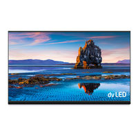
LED Wall bundle, Fine Pitch LED Video Display Indoor
Brand:
NEC
| Category:
Monitor
| Size: 13.05 MB
Table of Contents
Table of Contents
2
About this User Guide
9
Safety Symbols Used in this Manual
9
Service & Support in Europe
9
Safety and Compliance Guidelines
10
Qualification of Personnel
10
Personal Protection
10
General Safety Guidelines
11
Ambient Temperature
12
Risk of Fire
12
Safety for Electricity and Power Supply
12
Declaration of Conformity
14
About this Product
15
Scope of Delivery
15
List of Parts
15
Table 1: Materials and Parts Delivered for each Bundle
15
Framesets for Bundles
17
Frameset for LED-Fe012I2-110 and LED-Fe019I2-110 (4×4 Modules)
17
Figure 1: Frameset for LED-Fe012I2-110 and LED-Fe019I2-110 (4×4 Modules)
17
Table 2: FE Series Bundles
17
Frameset for LED-Fe015I2-137 (5×5 Modules)
18
Frameset for LED-Fe019I2-165 (6×6 Modules)
18
Figure 2: Frameset for LED-Fe015I2-137 (5×5 Modules)
18
Figure 3: Frameset for LED-Fe019I2-165 (6×6 Modules)
18
Specification
19
Table 3: Product Specification for Modules
19
LED Wall Components
20
Module
20
Figure 4: LED Wall Components
20
Figure 5: Type a Module - Front View
20
Figure 6: Module - Back Side
20
Figure 7: Type B Module - Open
20
Figure 8: Type a Module - Open
20
Cabinet
21
Figure 9: Type a Cabinet - Front
21
Figure 10: Type a and Type B Cabinet
21
Corner Alignment Pins
22
Screw Connection for Cabinets
22
Figure 11: Corner Alignment Pins
22
Figure 12: Screw Connections for Cabinets: Screws and Counter Plates
22
Grip Handles
23
Figure 13: Grip Handle in Open and Closed Positions
23
Figure 14: Grip Handles in Use
23
Cabinet Hanger Pins
24
Figure 15: Cabinet Hanger Pin
24
Figure 16: Installing Cabinet Hanger Pins
24
Figure 17: Cabinet Hanger Pin Connectors
24
Power Supply Socket
25
Figure 18: Power Supply Sockets - Top and Bottom
25
Figure 19: Connected Sockets
25
Figure 20: Sockets Wired to PDU Behind HUB
25
Pixel Card
26
Figure 21: Pixel Card - Back
26
Figure 22: Pixel Card - Front
26
Figure 23: Pixel Card Interfaces on Hub Board and in Cabinet
26
Figure 24: LED Chip and Usage of the Black Masks
27
Hub Board
28
Figure 25: Hub Board - Front
28
Figure 26: Hub Board - Back
28
Power Supply
29
Figure 27: Behind Hub Board -Power Supply with Wired PDU with PDU Shielding
29
Figure 28: Pin Connection from PDU to PSU
29
Signal Lights
30
Power Bar
30
Figure 29: Signal Lights on the Back of the Module
30
Figure 30: Signal Light Interface Connected to Hub Board
30
Figure 31: Power Bar with Cable Exit Point
30
Ventilation Requirements
31
Figure 32: Ventilation Space for Buried Installation
31
Heat Dissipation
32
Cooling
32
Figure 33: Ventilation Space for On-Wall Installation
32
Accessories
33
Power Supply and Connecting Cables
33
Power Supply for Power Bar
33
Signal Cable
33
Cabinet Alignment Bracket
33
Figure 34: Cabinet Alignment Bracket
33
Table 4: Compatible Signal Cable (Video Distributor)
33
Prepare for Use
34
List of Packaging Components
34
Table 5: Packaging Components
34
Cabinet Packaging
35
Pixel Cards Packaging
35
Figure 35: Cabinet Boxes Inside Case
35
Figure 36: Package Order of Module Box
35
Figure 37: Pixel Card Boxes Inside Case
35
Figure 38: Package Order of Pixel Card Box
35
Accessories and Spare Parts Packaging
36
Unpack the Components
36
Figure 39: Spare Parts Box
36
Figure 40: Service Tool Box
36
Figure 41: Hook on Wooden Box
36
Installation Setup - Wall Mounting
37
Table 6: Dimensions and Weight for LED Wall 4×4, 5×5, 6×6
37
Assemble Components
38
Install Frame Supports for Wall Mounting
38
Prepare the Wall Surface
38
Table 7: Frame Support - Installation Requirements
38
Draw and Mark the Anchor Positions on Wall
39
Figure 42: Positions for Anchor Points: 4×4 Frameset
39
Figure 43: Positions for Anchor Points: 5×5 Frameset
39
Figure 44: Positions for Anchor Points: 6×6 Frameset
39
Drill the Positions
40
Attach the Frame Supports
40
Figure 45: Wall Mounting: Attachment of Frame Supports (5×5 Frameset)
40
Figure 46: Using Alignment Bar with Spirit Level
40
Table 8: Number and Position for Anchor Points
40
Install Power Bar Onto Frame Supports
41
Check the Evenness
41
Bring Power Bar into Position
41
Attach Power Bar to Frame Supports
41
Figure 47: Wall Mounting: Attachment of Power Bar (5×5 Frameset)
41
Figure 48: Wall Mounting: Attachment of Power Bar (Detail)
41
Table 9: Power Bar Installation Requirements
41
Install Cabinets
42
Install Cabinet Hanger Pins on the Backside
42
Figure 49: Wall Mounting: Installation Order of Cabinets (4×4 Frameset)
42
Figure 50: Installing the Cabinet Hanger Pins
42
Table 10: Cabinet Installation Requirements
42
Install Cabinets for Bottom-Row on Power Bar
43
Figure 51: Installing the First Cabinet
43
Figure 52: Installing Additional Cabinets - First Row
43
Figure 53: Locking Two Modules
43
Secure Cabinet to Power Bar
44
Figure 54: Cabinet Screw Connections: Counter Plates (H), allen Screw Anchors (I)
44
Figure 55: Vertical Alignment of Cabinets
44
Figure 56: Fastening of First Row to Power Bar
44
Install Further Cabinet Rows
45
Align Cabinets
45
Figure 57: Locking Two Modules
45
Figure 58: Cabinet Alignment Brackets
45
Connect Power and Data Cables
46
Connect Data Cables
46
Connect Power Cables to the Power Bar
46
Figure 59: Connections in Power Bar
46
Figure 60: Connecting Two Cabinets
46
Table 11: Cable Connection Requirements
46
Check the Power Supply and Data Connection of the Modules
47
Install Frame Covers
47
Table 12: Frame Cover Installation Requirements
47
Figure 61: Installing Side Covers on Power Bar
48
Figure 62: Frame Cover Links
48
Figure 63: Installing Top Frame Cover
48
Figure 64: Installing Side Frame Covers
48
Figure 65: Fastening the Side Frame Covers
49
Figure 66: Installing Power Bar Cover Plate
49
Install Pixel Cards
50
Figure 67: Service Tool
50
Figure 68: Pixel Card
50
Figure 69: Pixel Card Positions in a Cabinet
50
Table 13: Pixel Card Installation Requirements
50
Figure 70: Installing the Pixel Cards
51
Figure 71: Level Screws
51
Getting Started
52
Info on the Connection Setup
52
Install Controller Software Novalct
52
Configure the Screen in Novalct (Loading Scr-Files)
53
Figure 72: Advanced User Login
53
Figure 73: Entering Password
53
Figure 74: Interface after Successful Login
53
Figure 75: Pop-Up Configurating the Screen Connection
54
Figure 76: Start Screen Configuration - Register Sending Card (Default View)
54
Figure 77: Start Screen - Screen Connection (Default View) before Configuration
55
Figure 78: Save Configuration
55
Figure 79: Screen Settings for 4×4 Controller
56
Figure 80: Screen Settings for 5×5 Controller (Left) and 6×6 Controller (Right)
56
Configure the Color and Brightness Settings in Novalct (Loading Fcg-File)
57
Figure 81: Starting Configuration Color and Brightness Settings
57
Figure 82: Start Screen Configuration Color and Brightness Settings
57
Figure 83: Starting the Import of the Fcg-Files
58
Figure 84: Successfully Import of the Fcg-Files
58
Update the Calibration Data after Installing All Pixel Cards
59
Figure 85: Start Screen - Starting Calibration
59
Figure 86: Start Screen for Screen Calibration
59
Figure 87: Screen Calibration - Register Manage Coefficients
60
Figure 88: Starting Screen Module Flash
60
Figure 89: Flash Module after Loading Module Calibration Data
61
Figure 90: Flash Module after Saving Module Calibration Data
61
Figure 91: Calibration Is Disabled
62
Figure 92: Calibration Is Enabled
62
Software Novalct
63
Function Overview
63
Figure 93: Start Screen Software Novalct
63
Table 14: Main Menus and Functions
63
Advanced User Login
66
Figure 94: Advanced User Login
66
Figure 95: Entering Password
66
Figure 96: Interface after Successful Login
66
Monitoring
67
Function Overview
67
Start Monitoring Function
67
Figure 97: Starting the Monitoring Function
67
Table 15: Monitoring - Main Functions
67
Receiving Card and Power Supplies
68
Figure 98: Start Screen Monitoring
68
Figure 104: Starting the Monitoring Function
68
Figure 105: Start Screen Monitoring Receiving Cards and Power Supplies
69
Sending Card
70
Figure 106: Starting the Monitoring Function
70
Figure 107: Start Screen Monitoring Receiving Cards and Power Supplies
70
Temperature
71
Figure 108: Start Screen Monitoring Sending Card
71
Figure 109: Starting the Monitoring Function
71
Figure 110: Start Screen Monitoring Receiving Cards and Power Supplies
72
Figure 111: Start Screen Monitoring Temperature
72
Maintenance
73
Routine Maintenance
73
Regular Cleaning
73
Power System Maintenance
74
Maintenance Tools
74
Figure 112: Pixel Card Service Tool
74
Figure 113: Mask Roller
74
Front Service
75
Change the Pixel Cards
75
Figure 114: Pixel Card
75
Remove the Hub Board
76
Figure 115: Foam Forms for Pixel Cards
76
Figure 116: Cabinet Without Pixel Cards
76
Figure 117: Screws on Hub Board
76
Figure 118: Removal of Hub Board
76
Change the Receiving Card
77
Change the Power Supply System
77
Figure 119: Replacing the Receiving Card
77
Spare Parts
79
Troubleshooting
80
Table 16: Troubleshooting Solutions
80
Table 17: Signal Light Codes FE
80
Disposal
81
Within the European Union
81
Outside the European Union
81
Copyright and Disclaimer
82
Copyright
82
Disclaimer
82
Appendix
83
Cable Plans
83
LED-Fe012I2-110, LED-Fe019I2-110: Data Connections
83
LED-Fe012I2-110, LED-Fe019I2-110: Power Connections
83
LED-Fe015I2-137: Data Connections
84
LED-Fe015I2-137: Power Connections
84
LED-Fe019I2-165: Data Connections
85
LED-Fe019I2-165: Power Connections
85
NEC FE Series Installation And Maintenance Manual (131 pages)
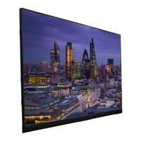
LED Module/LED Display
Brand:
NEC
| Category:
Monitor
| Size: 22.6 MB
Table of Contents
Table of Contents
2
Important Information
3
Parts Name
7
Model Name List
10
Contents
11
Installation Example
18
Installation Location
18
Handle
20
Mark the Positions of the Anchor Points on the Wall
20
Make the Holes at the Anchor Positions
22
Preparing Mounting Bar
23
Install the Mounting Bars
24
Install the Power Bar
26
Install the Cabinet Hanger Pins to the Back of the Cabinets
28
Install the Cabinets
30
Assembly Diagrams
36
Installation Without a Frame Set
39
Wiring
40
Installing the Pixel Card
60
Screen Configuration
62
Image Setting
73
Cleaning
83
Maintenance
84
Troubleshooting
89
Display Problems
89
Adjusting the Colors on a Part of the Screen
90
State Monitoring Using the Software
96
Redundancy Setting Method
101
Specifications (FA Series)
119
Specifications (FE Series)
123
Diagram
129
Advertisement
NEC FE Series Quick Start Manual (72 pages)
Fine Pitch LED Video Display Indoor, LED Wall Bundle
Brand:
NEC
| Category:
Monitor
| Size: 1.72 MB
Table of Contents
English
4
Table of Contents
4
1 About this User Guide
5
Safety Symbols Used in this Manual
5
2 Safety and Compliance Guidelines
6
Qualification of Personnel
6
Personal Protection
6
General Safety Guidelines
6
Risk of Fire
7
Safety for Electricity and Power Supply
7
Safe Usage of LED Lamps
8
3 About the LED WALL
9
Turn on the LED Wall
10
4 The Video Controller
11
Front and Rear Panel
11
Display and Menu
12
Select an Input Source
12
Adjust the Brightness
13
5 Troubleshooting
14
6 Disposal
15
Within the European Union
15
Outside the European Union
15
7 Copyright and Disclaimer
16
Copyright
16
Disclaimer
16
8 Service & Support in Europe
17
Русский
20
О Настоящем Руководстве
21
Символы Безопасности, Используемые В Настоящем Руководстве
21
Индивидуальная Защита
22
Квалификация Персонала
22
Общие Указания По Технике Безопасности
22
Указания По Технике Безопасности И Соответствию Требованиям
22
Безопасность Электричества И Электропитания
23
Риск Пожара
23
Безопасное Использование Светодиодных Ламп
24
О Светодиодной Стене
25
Включение Светодиодной Стены
26
Видеоконтроллер
27
Передняя И Задняя Панель
27
Выбор Источника Входного Сигнала
28
Дисплей И Меню
28
Регулировка Яркости
29
Поиск И Устранения Неисправностей
30
В Пределах Европейского Союза
31
За Пределами Европейского Союза
31
Утилизация
31
Авторские Права И Отказ От Ответственности
32
Авторское Право
32
Отказ От Ответственности
32
Обслуживание И Поддержка В Европе
33
Türkçe
36
1 Bu Kullanim Kilavuzu Hakkinda
37
Bu Kılavuzda Kullanılan Güvenlik Sembolleri
37
2 Güvenli̇k Ve Uygunluk Yönergeleri̇
38
Personelin Nitelikleri
38
Kişisel Korunma
38
Genel Güvenlik Talimatları
38
Yangın Tehlikesi
39
Elektrik Ve Güç Kaynağı GüvenliğI
39
LED Lambaların Güvenli KullanıMı
40
3 Led Duvar Hakkinda
41
LED Duvarın GüCünü Açma
42
4 Vİdeo Denetleyi̇Cİ
43
Ön Ve Arka Panel
43
Ekran Ve Menü
44
Bir Giriş Kaynağı Seçme
44
Parlaklığın Ayarlanması
45
5 Sorun Gi̇derme
46
6 İmha
47
Avrupa BirliğI Dahilinde
47
Avrupa BirliğI Dışında
47
7 Teli̇f Hakki Ve Yasal Uyari
48
Telif Hakkı
48
Yasal Uyarı
48
8 Avrupa'da Servi̇s Ve Destek
49
Advertisement
Related Products
NEC MultiSync FE750+
NEC FE991SB - MultiSync - 19" CRT Display
NEC FE950 - MultiSync - 19" CRT Display
NEC FE992-BK - MultiSync - 19" CRT Display
NEC FE700 - MultiSync - 17" CRT Display
NEC MultiSync FE950 FE950 FE950
NEC FE772M-BK - MultiSync - 17" CRT Display
NEC MultiSync FE950+
NEC MultiSync FE750 R
NEC MultiSync FE1250+
NEC Categories
Monitor
Projector
Server
Telephone
Laptop
More NEC Manuals
Login
Sign In
OR
Sign in with Facebook
Sign in with Google
Upload manual
Upload from disk
Upload from URL