
Related Manuals for Toro 41594


Summary of Contents for Toro 41594
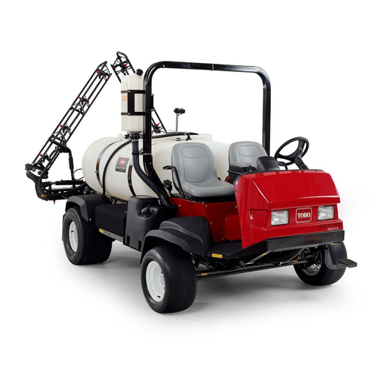
- Page 1 Form No. 3391-858 Rev B Multi-Pro 5800 Turf Sprayer Model No. 41594—Serial No. 315000001 and Up *3391-858* B Register at www.Toro.com. Original Instructions (EN)
- Page 2 Although Toro designs and produces safe products, you are responsible for operating the product properly and safely. You may contact Toro directly at www.Toro.com for product and accessory information, help finding a dealer, or to register your product.
-
Page 3: Table Of Contents
Contents Checking the PCV Valve..........46 Fuel System Maintenance ...........46 Checking the Fuel Line and Connections ....46 Safety ................4 Servicing the Fuel Filter...........46 Safe Operating Practices........... 4 Draining the Fuel Tank ...........48 Chemical Safety............5 Bleeding the Fuel System .........49 While Operating............ -
Page 4: Safety
Safety Note: Local regulations may restrict the age of the operator. • The owner/user can prevent and is responsible for Improper use or maintenance by the operator or owner can accidents or injuries occurring to himself or herself, other result in injury. To reduce the potential for injury, comply people, or damage to property. -
Page 5: Chemical Safety
Chemical Safety Checks in the Operation section. If the machine does not function correctly or is damaged in any way, do not use the sprayer. Make sure that the problem is corrected WARNING before the sprayer or attachment is operated. Chemical substances used in the spreader-sprayer •... -
Page 6: While Operating
• Do not clean spray nozzles by blowing through them or – Watch out for traffic when you are near or crossing placing in mouth. roads. Always yield the right of way to pedestrians and other vehicles. This sprayer is not designed for •... -
Page 7: Maintenance
• Do not adjust the traction control speed. To ensure WARNING safety and accuracy, have an Authorized Toro Distributor check the ground speed. Sudden changes in terrain may cause abrupt • Keep your body and hands away from pin hole leaks or steering wheel movement, possibly resulting in nozzles that eject high pressure fluid. -
Page 8: Sound Power
Sound Power Hand-Arm Vibration Measured vibration level for right hand = 0.2 m/s This unit has a guaranteed sound power level of 101 dBA, which includes an Uncertainty Value (K) of 1 dBA. Measured vibration level for left hand = 0.3 m/s Sound power level was determined according to the Uncertainty Value (K) = 0.1 m/s procedures outlined in ISO 11094. - Page 9 107-8724 1. Traction drive 3. To drive in reverse, press the bottom of the pedal rearward and down. 2. To drive forward, press the 4. Vehicle speed increases top of the traction pedal with more pedal pressure. forward and down. 117-4955 1.
- Page 10 120-0622 1. Warning—read the Operator's Manual. 2. Warning—do not enter the tank. 119-5046 3. Caustic liquid/chemical burn and toxic gas inhalation hazards—wear hand, skin, eye, and respiratory protection. 1. Read the Operator's Manual for information on fuses. 2. Foam marker—15 amp 3.
- Page 11 120-0625 1. Pinch point, hand—keep hands away. 107-8722 120-0617 1. Pinch point, hand—keep hands away from hinge. 1. Engaging the parking brake—1) Push down on the parking brake pedal; 2) Pull down on the parking brake lever to lock 2. Crushing hazard, boom—keep bystanders a safe distance the parking brake.
- Page 12 130-7076 1. Neutral engine speed lock 3. Off 2. On 127-6979 127-6981 127-6982 1. Pump 2. Boom spray...
- Page 13 130-7121 1. Pump 5. Light switch location 9. Raise boom 13. Center boom spray 2. Agitation 6. Left boom raise/lower 10. Fast 14. Right boom spray controls 3. On 7. Right boom raise/lower 11. Slow controls 8. Lower boom 4. Off 12.
-
Page 14: Setup
Kit or ProControl ™ ™ ™ XPKit is necessary for the proper function of the machine. To use the sprayer, you must obtain and install nozzles . Contact your Authorized Toro Distributor for information on the available boom kit and accessories. -
Page 15: Removing The Shipping Bumper
Removing the Shipping Bumper No Parts Required Procedure 1. Remove the bolts. washers, and nuts that secure the shipping bumper to the front chassis plate (Figure Figure 3 1. Boom hinge spring 2. Jam nut 4. Repeat the procedure for each spring on both boom hinges. -
Page 16: Product Overview
Product Overview Figure 5 1. Passenger seat 4. Roll Over Protection System (ROPS) 7. Pump 5. Tank lid 8. Battery 2. Operator’s seat 3. Fresh water tank 6. Chemical tank 9. Headlights Figure 6 1. Boom control cylinder 4. Fuel tank 7. -
Page 17: Controls
Controls G013753 Figure 7 1. Steering wheel 4. Storage 7. Traction pedal Figure 8 compartment 1. Master-boom switch 4. Traction pedal 2. Pressure 5. Center console 8. Arm rest gauge 2. Parking-brake pedal 5. Starter switch and key 3. Passenger 6. - Page 18 ensures the sprayer travels at a constant speed while driving Engine-Coolant Temperature Indicator the machine on level ground. Use the engine-coolant indicator (A of Figure 11) to see the temperature of the engine coolant. Note: You can change the temperature indicator between English and metric units;...
- Page 19 Hour Meter The hour meter (Figure 12) indicates the total number of hours the engine has run. The hour meter starts to function whenever the key is turned to the Run position. Figure 14 1. Master boom switch Boom Lift Switches The boom lift switches are located on the control panel to the right of the seat and used to raise the left and right booms Figure 12...
- Page 20 Important: Only engage the pump switch when the rotate the knob on the valve clockwise to turn the valve off or engine is at low idle to avoid damaging the pump drive. counterclockwise to turn it on. Note: Turning the section valve manually can interfere with Agitation Switch the function of the fuses.
-
Page 21: Specifications
Wheel base 198 cm (78 inches) Optional Equipment The Toro Company has optional equipment and accessories that you can purchase separately and install on your sprayer. Contact your Authorized Service Dealer for a complete list of optional equipment that is currently available for your sprayer. -
Page 22: Operation
0 C to 20 C (32 F to -4 F) SAE10W or SAE10W-30 sprayer for the day: Toro Premium Engine Oil is available from your distributor • Check the tire pressure. in either 15W40 or 10W30 viscosity. Refer to the Parts Catalog Note: These tires are different than car tires;... - Page 23 Checking the Coolant Level Service Interval: Before each use or daily Check the level of coolant in the radiator and the expansion tank at the beginning of each day before starting the engine. Coolant type: a solution of 50% soft water and 50% long life ethylene glycol antifreeze CAUTION If the engine has been running, the coolant may...
- Page 24 Toro distributor for part numbers.) 1. Hydraulic-oil tank 3. Dipstick cap Alternate hydraulic fluids: If the Toro fluid is not available, 2. Vent other fluids may be used provided they meet all the following material properties and industry specifications. We do not recommend the use of synthetic fluid.
- Page 25 Checking the Brakes DANGER Service Interval: Before each use or daily In certain conditions during fueling, static electricity can be released causing a spark which Before starting the sprayer, lightly press the brake pedal. If can ignite the gasoline vapors. A fire or explosion the pedal travels more than 2.5 cm (1 inch) before you feel from gasoline can burn you and others and can resistance, adjust the brakes;...
-
Page 26: Using The Infocenter
• Middle button—use this button to scroll down menus. • Right button—use this button to open a menu where a right arrow indicated additional content. Note: The purpose of each button may change depending on what is required at the time. Each button is labeled with an icon displaying its current function. - Page 27 • Left selection button: Sub-area sprayed (C of Figure • Left selection button: Tank volume (D of Figure Figure 28 Additional options for the HD-series models with an automatic transmission are not shown. 1. Right selection button (select context) 4. Press the right selection button to display to the Settings submenus.
- Page 28 Figure 29 1. List options (icon) 3. Right selection button (list context) 2. Scroll down (icon) 4. Center selection button (scroll context) Note: Pressing the left selection button will save your selection, exit the Settings menu, and return to the Main Menu.
-
Page 29: Preparing To Use The Sprayer
the Backlight menu, and return to the Settings menu (Figure 30). 6. To adjust the contrast level of the display, press the center selection button (the button below the down arrow icon in the display) to move the selected option down to the Contrast setting (Figure 30). -
Page 30: Operating The Machine
Setting the Ground Speed Lock Switch Note: Do not over tighten the tank strap hardware. CAUTION Operating the Machine If you press the ground speed lock switch and do not have your foot on the traction pedal, the traction Starting the Engine unit may suddenly stop and cause you to lose 1. -
Page 31: Breaking In A New Sprayer
Breaking in a New Sprayer As always, remember to clean your sprayer thoroughly after all applications. This will do the most to ensure your sprayer To provide proper performance and long sprayer life, follow has a long and trouble free life. these guidelines for the first 100 operating hours: Note: If you have questions or need additional information •... -
Page 32: Operating The Booms
Important: Prior to introducing wettable powders back into the transport position. Make sure the boom into any Toro Spray System mix the powders in cylinders are fully retracted to prevent actuator rod damage a suitable container with sufficient fresh water to during storage. -
Page 33: Turf Care Precautions While Operating In Stationary Modes
• Minimize the amount of time the machine is left Toro recommends using the approved rinse kit for this running over any particular area of turf. Both time and machine. Contact your Authorized Toro Dealer for more temperature affect how much the grass may be damaged. -
Page 34: Calibrating The Section Valves
the drain valve to the machine and let the valve rest on 13. Repeat steps through at least 2 more times to the ground. This allows any residual material in the ensure that the spray system is fully cleaned. line to drain. Important: You must always complete this procedure at least 3 times to ensure that the spray system is fully clean, preventing damage to the... -
Page 35: Agitation Bypass Valve Knob Position
(typically 276 kPa or 40 psi); refer to the nozzle selection guide that is available through your Authorized Toro Dealer. 7. Record the reading on the pressure gauge. 8. Turn off 1 of the boom section using the appropriate section switch. -
Page 36: Pump
Transporting the Sprayer For moving the sprayer long distances, use a trailer. Secure the sprayer to the trailer. Also, make sure the booms are tied down and secure. Figure 41 Figure 42 illustrate the tie-down points. Figure 39 Figure 41 1. - Page 37 Figure 45 1. Rear towing points 3. Release the parking brake. Figure 43 4. Tow the sprayer at less than 4.8 kph (3 mph). 1. Tow valve 5. When finished, close the tow valve and torque it to no more than 7 to 11 N-m (5 to 8 ft-lb). Important: If you do not open the tow valve before towing the sprayer you will damage the transmission.
-
Page 38: Maintenance
Maintenance Recommended Maintenance Schedule(s) Maintenance Service Maintenance Procedure Interval • Replace the hydraulic oil filter. After the first 5 hours • Torque the wheel lug nuts. • Change the rear planetary gearbox fluid. After the first 8 hours • Check the fan/alternator belt •... -
Page 39: Daily Maintenance Checklist
Note: Looking for an Electrical Schematic or Hydraulic Schematic for your machine? Download a free copy of the schematic by visiting www.Toro.com and searching for your machine from the Manuals link on the home page. Daily Maintenance Checklist Duplicate this page for routine use. -
Page 40: Premaintenance Procedures
CAUTION If you leave the key in the starter switch, someone could accidently start the engine and seriously injure you or other bystanders. Remove the key from the starter switch before you do any maintenance. Premaintenance Accessing the Engine Procedures Removing the Forward Heat Shield 1. - Page 41 Installing the Engine Heat Shield 1. Align the rear flange of the forward heat shield over the forward flange of the rear heat shield (Figure 49). Figure 49 1. Front of the machine 3. Rear flange (forward heat shield) 2. Hex-head bolts and 4.
-
Page 42: Lubrication
Every 50 hours/Yearly (whichever comes first) Grease Type: No. 2 general-purpose, lithium-based grease. Grease Type: No. 2 general-purpose, lithium-based grease. Toro Premium All Purpose Grease is available from your 1. Wipe the grease fittings clean so that foreign matter Toro Distributor. -
Page 43: Engine Maintenance
Engine Maintenance Checking the Air Cleaner Service Interval: Before each use or daily Service the air cleaner more frequently if operating conditions are extremely dusty or sandy. 1. Set the parking brake, stop the pump, stop the engine, and remove the key from the starter switch. 2. -
Page 44: Servicing The Engine Oil
SAE10W or SAE10W-30 position) 3. Latch (dust cap) 7. Pressure relief hose Toro Premium Engine Oil is available from your distributor 4. Dust cap 8. Tank-vent hose in either 15W40 or 10W30 viscosity. Refer to the Parts Catalog for part numbers. - Page 45 Changing the Engine Oil Filter Changing the Engine Oil 1. Align a drain pan with a 9 L (9.5 US qt) capacity or 1. Remove the forward heat shield; refer to Removing the greater under the drain plug (Figure 58). Forward Heat Shield (page 40).
-
Page 46: Checking The Pcv Valve
Fuel System Important: Overfilling the engine with oil may cause damage to the engine. Maintenance 8. Install the oil filler cap into the filler neck and the dipstick into the dipstick tube (Figure 59). DANGER 9. Start the engine and check for oil leaks. Under certain conditions, fuel and fuel vapors are 10. - Page 47 5. Rotate the nut for the fuel pump/sending unit counterclockwise and remove the nut and seal (Figure 6. Carefully lift and rotate the fuel pump/sending unit out of the neck of the fuel tank (Figure 62). Important: Use caution when handling the fuel pump/sending unit to avoid damaging the arm for the float of the sending unit.
-
Page 48: Draining The Fuel Tank
Replacing the Fuel Filter 4. Connect the coupling on the fuel hose to the fitting of the fuel pump (Figure 62). 1. Remove the pickup tube of the fuel filter from the fitting of the fuel pump (Figure 63). Note: Ensure that the locking sleeve of the fuel-hose coupling secures the coupling to the pump fitting. -
Page 49: Bleeding The Fuel System
Bleeding the Fuel System Electrical System Maintenance Use this procedure after you have serviced the fuel filter or ran the engine out of fuel, and the engine does not start. 1. Ensure that you have 1/2 tank of fuel in the fuel tank. Replacing the Fuses 2. -
Page 50: Charging The Battery
Voltage: 12 volts with 690 cold cranking Amps at 0 degrees WARNING F (-18 degrees C) Battery terminals or metal tools could short against metal sprayer components causing Removing the Battery sparks. Sparks can cause the battery gasses to 1. Move the sprayer on a level surface, set the parking explode, resulting in personal injury. -
Page 51: Drive System Maintenance
Storing the Battery Drive System If the machine will be stored for more than 30 days, remove Maintenance the battery and charge it fully. Either store it on the shelf or on the machine. Leave the cables disconnected if it is stored on the machine. -
Page 52: Adjusting The Front Wheel Toe-In
2. Measure the distance between both of the front tires at the axle height at both the front and rear of the front tires (Figure 69). The distance between the front of the tires should be 0 to 3 mm (0 to 1/8 inch) less than the distance between the back side of the front tires. -
Page 53: Cooling System Maintenance
Cooling System Maintenance Servicing the Cooling System Service Interval: Every 100 hours—Check the cooling system hoses for wear and damage. Every 400 hours/Yearly (whichever comes first)—Check the coolant (as directed by the manufacturer) and change if necessary. Cooling system capacity: 5.5 L (5.8 US qt) Coolant type: a solution of 50% water and 50% permanent ethylene glycol antifreeze Important: Do not add coolant to an overheated engine... -
Page 54: Brake Maintenance
Brake Maintenance Note: Use enough coolant to fill the engine and the system lines. This will allow for the coolant to expand without it overflowing while the engine is warming up. Adjusting the Brakes 8. Start the engine with the cap loosely on the radiator (Figure 71). -
Page 55: Belt Maintenance
2. Check the tension by depressing the belt midway between the alternator and the crankshaft pulleys with Alternate fluids: If the Toro fluid is not available, other 10 kg (22 lb) of force. fluids may be used provided they meet all the following Note: The belt should deflect 10 to 12 mm (0.39 to... -
Page 56: Servicing The Hydraulic Oil
Service Interval: After the first 5 hours Every 400 hours/Yearly (whichever comes first) 3. Clean the area around the filter mounting area. Use the Toro replacement filter (See your Parts Manual for the 4. Place a drain pan under the filter. correct part number.) 5. - Page 57 WARNING Hydraulic fluid escaping under pressure can penetrate skin and cause injury. • Ensure that all hydraulic fluid hoses and lines are in good condition and all hydraulic connections and fittings are tight before applying pressure to the hydraulic system. •...
-
Page 58: Sprayer System Maintenance
Sprayer System 2. Align a drain pan under the pressure filter (Figure 78). Maintenance WARNING Chemical substances used in the spray system may be hazardous and toxic to you, bystanders, animals, plants, soils or other property. • Carefully read and follow the chemical warning labels and Material Safety Data Sheets (MSDS) for all chemicals used and protect yourself according to the chemical... -
Page 59: Inspecting The Sprayer Pump
Note: The following machine components are considered parts subject to consumption through use unless found defective and are not covered by the Warranty associated with this machine. Have an Authorized Toro Service Distributor check following internal pump components for damage: • Pump diaphragm •... -
Page 60: Inspecting The Nylon Pivot Bushings
Inspecting the Nylon Pivot Cleaning Bushings Cleaning the Radiator Cooling Service Interval: Every 400 hours/Yearly (whichever comes Fins first) 1. Position the sprayer on a level surface, set the parking Service Interval: Every 200 hours—Clean the radiator fins. brake, stop the pump, stop the engine, and remove the Important: Do not spray water into a hot engine key from the starter switch. - Page 61 Removing the Master Boom Manifold Valve (page Cleaning the Manifold Valve (page 65) Assembling the Manifold Valve (page 66) Installing the Master Boom Manifold Valve (page Installing the Valve Actuator (page 69) • To clean the 3 section valves; refer to the following sections: Removing the Valve Actuator (page 61) Removing the Section Manifold Valve (page 64)
- Page 62 Removing the Rate Control Manifold Valve 1. Remove clamps and gaskets that secure the manifold for the rate control valve (Figure 83). Note: Retain the clamp(s) and gasket(s)for installation Installing the Rate Control Manifold Valve (page 67). Figure 84 1. Flanged-head bolt 4.
- Page 63 Removing the Master Boom Manifold Valve 1. Remove clamps and gaskets that secure the manifold for the master boom valve (Figure 87) to the master boom bypass valve, agitation valve, and 90° flanged elbow (at the end of the hose for the flow meter). Note: Retain the clamp(s) and gasket(s)for installation Installing the Master Boom Manifold Valve (page 68).
- Page 64 Figure 88 1. Flanged-head bolt 3. Valve mount 4. Flanged locknut 2. Manifold (master boom valve) Removing the Section Manifold Valve 1. Remove clamps and gaskets that secure the manifold Figure 90 for the section valve (Figure 89) to the adjacent section valve (if left section valve, and the reducer coupling).
- Page 65 Figure 93 Agitation Valve Manifold Figure 91 1. Stem retainer 7. Back seating O-ring (0.676 inch / 0.07 inch) 1. Bypass fitting 2. Section valve manifold 2. Valve stem 8. Valve seat ring 3. Stem port 9. Mainfold body 4. Stem capture retainer 10.
- Page 66 Assembling the Manifold Valve 1. Check the condition of the outlet fitting O-rings (section valve manifold only), endcap O-rings, back seating O-rings, ball seat for damage or wear (Figure 93 Figure 94). Note: Replace any damaged or worn O-rings or seats. 2.
- Page 67 Installing the Rate Control Manifold 5. Assemble the rate control valve to the valve mount with the 2 flanged-head bolts and 2 flanged locknuts (A of Valve Figure 96) that you removed in step Removing the 1. Align a 1 gasket between the flanges of the rate control Rate Control Manifold Valve (page 62) and torque the valve manifold and the pressure filter head (A of...
- Page 68 8. Assemble the agitation valve manifold, gasket, and adapter fitting with a clamp tightened hand tight (C of Figure 97). 9. Assemble the agitation valve to the valve mount with the flanged-head bolt and flanged locknut that you removed in step Removing the Agitation Manifold Valve (page 62) and torque the nut and bolt to 1017 to...
- Page 69 3. Align the flange of the master boom valve manifold, 1 4. Secure the endcap fitting to the outlet fitting by gasket, and the agitation valve manifold (B of Figure inserting a retainer into the socket of the outlet fitting 98).
-
Page 70: Storage
Storage E. Change the engine oil filter and oil; refer to Changing the Engine Oil Filter (page 45) Changing the Engine Oil (page 45). 1. Position the sprayer on a level surface, set the parking brake, stop the pump, stop the engine, and remove the F. -
Page 71: Troubleshooting
Troubleshooting Troubleshooting the Engine and Vehicle Problem Possible Cause Corrective Action The starter does not rotate the engine. 1. The electrical connections are 1. Check the electrical connections for corroded or loose. good contact. 2. A fuse is blown or loose. 2. - Page 72 Problem Possible Cause Corrective Action The engine loses power. 1. The crankcase oil level is incorrect. 1. Fill or drain to the Full mark. 2. The air cleaner element is dirty. 2. Replace.the air cleaner element. 3. Dirt, water, or stale fuel is in the fuel 3.
- Page 73 Problem Possible Cause Corrective Action A boom actuator is not operating properly. 1. A thermal breaker in the fuse block 1. Wait for the system to cool down before responsible for powering the actuator resuming operation. If the thermal has tripped due to overheating. breakers trip repeatedly, contact your Authorized Service Dealer.
-
Page 74: Schematics
Schematics Flow Diagram (Rev. A) - Page 75 The Way Toro Uses Information Toro may use your personal information to process warranty claims, to contact you in the event of a product recall and for any other purpose which we tell you about. Toro may share your information with Toro's affiliates, dealers or other business partners in connection with any of these activities. We will not sell your personal information to any other company.
- Page 76 Countries Other than the United States or Canada Customers who have purchased Toro products exported from the United States or Canada should contact their Toro Distributor (Dealer) to obtain guarantee policies for your country, province, or state. If for any reason you are dissatisfied with your Distributor's service or have difficulty obtaining guarantee information, contact the Toro importer.