
Related Manuals for Toro 41582


Summary of Contents for Toro 41582
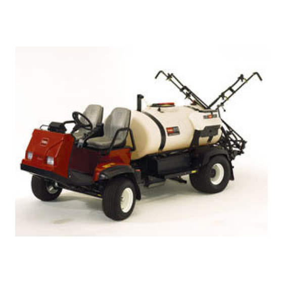
- Page 1 Form No. 3360-879 Rev A Multi-Pro 5700-D Turf Sprayer Model No. 41582—Serial No. 280000274 and Up G005648 Register at www.Toro.com. Original Instructions (EN)
-
Page 2: Table Of Contents
Important calls attention to special products, you are responsible for operating the product mechanical information and Note emphasizes general properly and safely. You may contact Toro directly at information worthy of special attention. www.Toro.com for product and accessory information, help finding a dealer, or to register your product. - Page 3 Think Safety First ..........19 Belt Maintenance............ 48 Before Driving the Sprayer for the First Servicing the Drive Belts........48 Time .............. 19 Hydraulic System Maintenance ....... 48 Pre-Starting Checks ..........22 Checking the Hydraulic Fluid......48 Driving the Sprayer..........22 Servicing the Hydraulic Oil .........
-
Page 4: Safety
Chemical Safety Safety Improper use or maintenance by the operator or owner can result in injury. To reduce the potential for injury, Chemical substances used in the spray system comply with these safety instructions and always pay attention to the safety alert symbol, which means may be hazardous and toxic to you, bystanders, animals, plants, soils or other property. -
Page 5: Before Operating
• Properly dispose of unused chemicals and the Pre-Starting Checks in the Operation section. chemical containers as instructed by the chemical If the machine does not function correctly or is manufacturer and your local codes. damaged in any way, do not use the sprayer. Make sure that the problem is corrected before the sprayer •... - Page 6 3. Turn the ignition key to Off. • The Toro Company strongly recommends installing 4. Remove the ignition key. the optional ROPS Kit when operating on hilly terrain. If you install a ROPS, always wear the seat Important: Do not park the machine on an belt when driving the sprayer.
-
Page 7: Maintenance
• Reduce your speed when operating on rough terrain • Do not adjust the traction control speed. To and near curbs. ensure safety and accuracy, have an Authorized Toro Distributor check the ground speed. • Grip the steering wheel loosely around the perimeter. -
Page 8: Safety And Instructional Decals
Safety and Instructional Decals Safety decals and instructions are easily visible to the operator and are located near any area of potential danger. Replace any decal that is damaged or lost. 94-3353 1. Crushing hazard of hand—keep your hands a safe distance away. - Page 9 104-9129 1. Warning—read the 4. On Operator’s Manual. 2. Lock and engage 5. Off 3. Cruise control 105-7506 1. Read the Operator’s 4. Engine—preheat Manual. 2. Engine—stop 5. Engine—start 3. On 106-5217 106-1355 1. Fast 12. Right boom 1. Warning—do not enter the tank. 2.
- Page 10 106-5517 1. Warning—do not touch the hot surface. 107-8720 1. Crushing/dismemberment hazard—do not start the engine while entering or exiting the vehicle; engage the parking brake, insert the key, and start the engine while seated in 107-8666 the drivers seat; read the Operator’s Manual. 1.
- Page 11 107-8731 1. Warning—read the Operator’s Manual. 2. Torque lug nuts to 55-75 ft-lb (75-102 N-m). 107-8732 1. Warning—read the Operator’s Manual. 107-8724 2. Torque lug nuts to 75-90 ft-lb (95-122 N-m). 1. Traction drive 3. To drive in reverse, press the bottom of the pedal rearward and down.
-
Page 12: Setup
Note: Determine the left and right sides of the machine from the normal operating position. Important: To use the sprayer, you must obtain and install nozzles . Contact your Authorized Toro Distributor for information on the available boom kits and accessories. After you install your nozzles and before using the sprayer for the first time (if you do not use Pro Control™... -
Page 13: Learning More About Your Product
2. View the Operator training material. 5. Move the booms into the transport “X” position. 3. Complete the registration card and return to Toro. See Operating the Booms in the Operation section for more information. 4. Store the documentation in a safe place. -
Page 14: Product Overview
Product Overview G002197 Figure 4 1. Operator’s position 4. Chemical tank 7. Tank lid 10. Pump pressure dampener 2. Passenger’s position 5. Fuel tank 8. Pump 11. Battery 3. Headlight 6. Anti-Siphon Receptacle 9. Fresh water tank 12. Tank drain Figure 5 3. -
Page 15: Controls
Controls G002199 Figure 6 1. Steering wheel 4. Dash controls 7. Throttle lever 2. Master boom foot switch 5. Traction pedal 8. Operator’s position 3. Pressure gauge 6. Sprayer controls 9. Passenger position Traction Pedal Fast position and press the traction pedal all the way forward. - Page 16 Pressure Gauge brake pedal. If the sprayer is parked on a steep grade, apply the parking brake and place the blocks on the The pressure gauge (Figure 9). is located on the dash. downhill side of the wheels. This gauge shows the pressure of the fluid in the system in psi and kPa.
- Page 17 Figure 11 1. Fuel gauge Figure 13 1. Boom switches, left, right 4. Agitation Master Boom Switch and center 2. Pump switch 5. Boom lift switch, left and The master boom switch is located on the floor board right of the machine cab and to the left of the operator. It 3.
- Page 18 Foam Marker Switch Locations Anti-siphon Fill Receptacle (Optional) To the front of the tank cover is a hose receptacle with a threaded fitting, a 90 degree barbed fitting, and a short If you install the foam marker kit, you will add switches hose which you can direct toward the tank opening.
-
Page 19: Specifications
2. Remove the dipstick, located under the passenger seat, and wipe it with a clean rag (Figure 16). Insert The Toro Company has optional equipment and the dipstick into the tube and make sure it is seated accessories that you can purchase separately and install fully. - Page 20 Add Fuel the dipstick; refer to Servicing Engine Oil, in the Engine Maintenance section, for the proper oil type and viscosity. Add the oil slowly and check the level often during this process. Do not overfill. In certain conditions, fuel is extremely flammable and highly explosive.
- Page 21 • Fuel filter plugging may be expected for a time after converting to biodiesel blendsd. In certain conditions during fueling, static • Contact your distributor if you wish for more electricity can be released causing a spark information on biodiesel. which can ignite the fuel vapors.
-
Page 22: Pre-Starting Checks
Note: These tires are different than car tires; they require less pressure to minimize turf compaction and damage. Under certain conditions, diesel fuel and fuel vapors are highly flammable and explosive. A • Check all fluid levels and add the appropriate fire or explosion from fuel can burn you and amount of specified fluids, if any are found to be others and can cause property damage. -
Page 23: New Sprayer Break-In
Note: Stopping distance may vary depending on • Avoid hard braking situations for the first several the sprayer load and speed. hours of new sprayer break-in operation. New brake linings may not be at optimum performance until several hours of use has caused the brakes to Setting the Cruise Control become burnished (broken-in). -
Page 24: Filling The Fresh Water Tank
To open the fresh water tank spigot, turn the lever on the spigot. Chemicals are hazardous and can cause personal injury. • Read the directions on the chemical labels before handling the chemicals and follow all manufacturer recommendations and precautions. •... -
Page 25: Operating The Booms
6. Set the agitation switch to the On position. Important: Prior to introducing wettable Spraying powders into any Toro Spray System mix the powders in a suitable container with sufficient Important: In order to ensure that your solution fresh water to create a free flowing slurry. Best remains well mixed, use the agitation feature results may be obtained by using warm water. -
Page 26: Spraying Tips
agitation, hand spraying with a spray gun, or using 1. Stop the sprayer on a level surface, stop the engine, a walking boom. and set the parking brake. 2. Set the master boom switch to the Off position and Use the following precautions: set the pump switch to the Off position. -
Page 27: Calibrating The Boom Bypass Valves
13. Repeat steps 4 through 12 at least 2 more times to ensure that the spray system is fully cleaned. Important: You must always complete this procedure at least 3 times to ensure that the spray system is fully clean, preventing damage to the system. -
Page 28: Pump
until the pressure reading on the gauge is the same pressure in the dampener is 1/3 of the spraying as it was in step 7. pressure. If using a spray pressure greater than 45 psi (3.1 bar) adjust the dampener accordingly. Transporting the Sprayer For moving the sprayer long distances, use a trailer. - Page 29 Towing the sprayer is a two person job. If the machine must be moved a considerable distance, transport it on a truck or trailer; refer to Transporting the Sprayer. 1. Rotate the tow valve (Figure 26) 90 degrees in either direction to open it.
-
Page 30: Maintenance
• Change the hydraulic oil. • Inspect the O-rings in the valve assemblies and replace them if necessary. • Inspect the pump diaphragm and replace if necessary. (see an Authorized Toro Service Distributor) • Inspect the pressure dampener bladder and replace if necessary. (see an Authorized... -
Page 31: Daily Maintenance Checklist
Maintenance Service Maintenance Procedure Interval • Inspect the pump check valves and replace if necessary. (see an Authorized Toro Service Distributor) • Check boom actuator hydraulic oil for air bubbles. • Inspect the nylon pivot bushings. • Flush the sprayer with clean water using the Cleaning the Sprayer procedure. During the rinse procedure, increase pump speed to open relief valve;... -
Page 32: Notation For Areas Of Concern
Notation for Areas of Concern Inspection performed by: Item Date Information If you leave the key in the ignition switch, someone could accidently start the engine and seriously injure you or other bystanders. Remove the key from the ignition before you do any maintenance. Premaintenance Procedures Jacking the Sprayer... -
Page 33: Lubrication
Service Interval: Every 50 hours—Lubricate the pump. Every 50 hours/Yearly (whichever comes first) Grease Type: No. 2 general-purpose lithium base grease. Toro Premium All Purpose Grease is available from you Toro Distributor. 1. Wipe the grease fitting clean so that foreign matter Figure 31 cannot be forced into the bearing or bushing. -
Page 34: Greasing The Boom Hinges
2. Pump grease into the bearing or bushing at each fitting Figure 35. Figure 33 Three inside each front wheel 1. Grease point Figure 35 Right boom 1. Grease fitting 3. Wipe off excess grease. 4. Repeat the procedure for each boom pivot. Greasing the Actuator Rod Bearings Service Interval: Every 400 hours/Yearly (whichever... - Page 35 7. With the pin in place, release the boom and secure the pin with the cotter removed previously. 8. Repeat the procedure for each actuator rod bearing. G002016 Figure 36 1. Actuator 4. Cotter 2. Actuator rod 5. Pin 3. Boom pivot pin housing 3.
-
Page 36: Engine Maintenance
3. Loosen the air cleaner strap that secures the air cleaner cover to the air cleaner body (Figure 38) and Toro Premium Engine Oil is available from your separate the cover from the body. distributor in either 15W40 or 10W30 viscosity. See the Parts Catalog for part numbers. - Page 37 the oil level is at or below the ’add’ mark on the dipstick, 4. Install the filler cap. add oil to bring the oil level to the ’full’ mark. Do not 5. Install the dipstick firmly in place. overfill. If the oil level is between the ’full’ and ’add’ marks, no oil addition is required.
-
Page 38: Fuel System Maintenance
Fuel System Maintenance Under certain conditions, diesel fuel and fuel vapors are highly flammable and explosive. A fire or explosion from fuel can burn you and others and can cause property damage. • Use a funnel and fill the tank outdoors, in an open area, when the engine is off and is cold. -
Page 39: Bleeding Air From The Injectors
Under certain conditions, diesel fuel and fuel vapors are highly flammable and explosive. A fire or explosion from fuel can burn you and others and can cause property damage. • Use a funnel and fill the fuel tank outdoors, in an open area, when the engine is off and is cold. -
Page 40: Servicing The Fuel Filters
3. Replace with a new filter fitting. Contact your local 6. Use fresh fuel to fill the tank. Authorized Toro Dealer to obtain the correct part. Servicing the Fuel Filters 4. Install the hose over the barb of the new filter fitting and secure it with the existing clamp. -
Page 41: Electrical System Maintenance
Electrical System Always keep the battery clean and fully charged. Use a paper towel to clean the battery and battery box. If Maintenance the battery terminals are corroded, clean them with a solution of 4 parts water and 1 part baking soda. Apply a light coating of grease to the battery terminals to Replacing the Fuses prevent corrosion. -
Page 42: Charging The Battery
Battery terminals or metal tools could short Charging the battery produces gasses that can against metal sprayer components causing explode. sparks. Sparks can cause the battery gasses to Never smoke near the battery and keep sparks explode, resulting in personal injury. and flames away from battery. -
Page 43: Drive System Maintenance
Drive System Maintenance Check the Tire Pressure Service Interval: Before each use or daily Check the tire pressure every 8 hours or daily to ensure proper levels. Fill the tires to 18 psi (124 kPa). Also, check the tires for wear or damage. Figure 48 1. -
Page 44: Adjusting The Front Wheel Toe-In
Figure 51 G002016 1. Tire center line-back 3. Axle center line Figure 50 2. Tire center line-front 1. Upper hole, add fluid here 2. Lower hole 3. If the measurement does not fall within the specified range, loosen the jam nuts at both ends of the tie 6. -
Page 45: Cooling System Maintenance
Cooling System 5. If coolant level is low, remove the expansion tank cap and the radiator cap, and fill expansion tank to Maintenance the Full mark and the radiator to the top of the filler neck. Do not overfill the expansion tank. Important: Do not use water only or an Checking the Coolant Level alcohol/methanol-based coolant. - Page 46 Note: This usually occurs between 175 and 190 degrees F. As the engine continues to run, the coolant will become hot and pressurized. If you open the radiator cap when the coolant is hot, it could spray out and severely burn you or bystanders. Wear protective clothing and avoid contact with hot coolant as you open the radiator cap.
-
Page 47: Brake Maintenance
Brake Maintenance 6. Tighten the rear nuts equally until the brake pedal moves between 1/2 to 1 inch (1 to 2 cm) before you feel resistance (Figure 56). Checking the Brakes Important: Ensure that you tighten both rear Service Interval: Before each use or daily nuts equally so that the threaded ends of the brake cables in front of the front nuts are the Before starting the sprayer, lightly press the brake pedal. -
Page 48: Belt Maintenance
Belt Maintenance Hydraulic System Maintenance Servicing the Drive Belts Checking the Hydraulic Fluid Service Interval: After the first 8 hours Every 100 hours Service Interval: Before each use or daily Check the condition and tension of the 1. Position the sprayer on a level surface, set the parking alternator/cooling fan belt. -
Page 49: Servicing The Hydraulic Oil
Every 400 hours/Yearly (whichever Service Interval: Every 400 hours/Yearly (whichever comes first) comes first) Use the Toro replacement filter (See your Parts Manual Use 10.6 US gallons (40.1 l) of Mobil DTE 15M for the correct part no.) hydraulic fluid or equivalent. - Page 50 Hot hydraulic fluid can cause severe burns. Hydraulic fluid escaping under pressure can penetrate skin and cause injury. Allow the hydraulic oil to cool before performing • Ensure that all hydraulic fluid hoses and any maintenance to the hydraulic system. lines are in good condition and all hydraulic connections and fittings are tight before 1.
-
Page 51: Spray System Maintenance
Protective Equipment (PPE) including Warranty associated with this machine. face and eye protection, gloves, or other Have an Authorized Toro Service Distributor check equipment to guard against personal contact following internal pump components for damage: with the chemical. -
Page 52: Emergency Manual Operation Of The Boom Actuators
Emergency Manual Operation of the Boom Actuators Note: Determine the left and right sides of the machine from the normal operating position. Use of the manual relief valve may cause the boom to move suddenly and cause injury to you or others. -
Page 53: Cleaning
Cleaning Cleaning the Suction Strainer Service Interval: Before each use or daily 1. Position the sprayer on a level surface, set the parking brake, stop the pump, stop the engine, and remove the ignition key. 2. Remove the retainer from the red fitting attached to the large hose on the top of the tank (Figure 63). -
Page 54: Storage
Storage the Battery in the Electrical System Maintenance section. 1. Position the sprayer on a level surface, set the parking Note: Do not connect the battery cables to the brake, stop the pump, stop the engine, and remove battery posts during storage. the ignition key. -
Page 55: Troubleshooting
Troubleshooting Troubleshooting the Engine and Vehicle Problem Possible Cause Corrective Action The starter does not crank. 1. The range selector is in a gear other 1. Press the brake pedal and move the than Neutral. range selector to the Neutral position. 2. - Page 56 Problem Possible Cause Corrective Action 8. The air cleaner element is dirty. 8. Clean or replace. The engine overheats. 1. The crankcase oil level is incorrect. 1. Fill or drain to the full mark. 2. Excessive loading. 2. Reduce load; use lower ground speed. 3.
- Page 57 Problem Possible Cause Corrective Action A boom section does not turn off. 1. The valve is damaged. 1. Stop the spray system and pump and turn off the sprayer. Remove the retainer from under the boom valve and pull out the motor and stem. Inspect all parts and replace any that appear damaged.
-
Page 58: Schematics
Schematics Electrical Schematics, Vehicle (Rev. B) - Page 59 G009414 Electrical Schematic, Spray System (Rev. A)
- Page 60 Countries Other than the United States or Canada Customers who have purchased Toro products exported from the United States or Canada should contact their Toro Distributor (Dealer) to obtain guarantee policies for your country, province, or state. If for any reason you are dissatisfi ed with your Distributor’s service or have diffi...