ABB REG670 Technical Manual
Relion 670 series
2.0 iec
generator protection
Hide thumbs
Also See for REG670:
- Applications manual (780 pages) ,
- Commissioning manual (324 pages) ,
- Product manual (146 pages)
Table of Contents
Advertisement
Quick Links
Advertisement
Table of Contents

Related Manuals for ABB REG670


Summary of Contents for ABB REG670
- Page 1 ® Relion 670 series Generator protection REG670 2.0 IEC Technical manual...
- Page 3 Document ID: 1MRK502052-UEN Issued: July 2016 Revision: B Product version: 2.0 © Copyright 2014 ABB. All rights reserved...
- Page 4 Copyright This document and parts thereof must not be reproduced or copied without written permission from ABB, and the contents thereof must not be imparted to a third party, nor used for any unauthorized purpose. The software and hardware described in this document is furnished under a license and may be used or disclosed only in accordance with the terms of such license.
- Page 5 In case any errors are detected, the reader is kindly requested to notify the manufacturer. Other than under explicit contractual commitments, in no event shall ABB be responsible or liable for any loss or damage resulting from the use of this manual or the application of the equipment.
- Page 6 (EMC Directive 2004/108/EC) and concerning electrical equipment for use within specified voltage limits (Low-voltage directive 2006/95/EC). This conformity is the result of tests conducted by ABB in accordance with the product standard EN 60255-26 for the EMC directive, and with the product standards EN 60255-1 and EN 60255-27 for the low voltage directive.
-
Page 7: Table Of Contents
Table of contents Table of contents Section 1 Introduction..............39 This manual..................39 Intended audience................39 Product documentation..............40 Product documentation set............40 Document revision history............41 Related documents..............42 Document symbols and conventions..........42 Symbols..................42 Document conventions..............43 IEC 61850 edition 1 / edition 2 mapping........44 Section 2 Available functions............ - Page 8 Table of contents Identification................77 Function block................77 Signals..................78 Basic part for LED indication module..........78 Identification................78 Function block................79 Signals..................79 Settings..................80 Monitored data................80 LCD part for HMI function keys control module........80 Identification................80 Function block................81 Signals..................81 Settings..................81 Operation principle................
- Page 9 Table of contents Settings..................142 Monitored data................143 Operation principle..............143 Logic diagram...............144 Technical data................145 Generator differential protection GENPDIF ........146 Identification................146 Functionality................146 Function block................147 Signals..................147 Settings..................148 Monitored data................150 Operation principle..............150 Function calculation principles..........151 Fundamental frequency differential currents......151 Supplementary criteria............
- Page 10 Table of contents Operation principle..............180 Full scheme measurement........... 180 Impedance characteristic............. 181 Basic operation characteristics..........182 Theory of operation.............. 184 Simplified logic diagrams............193 Technical data................197 Directional impedance element for mho characteristic ZDMRDIR. 197 Identification................197 Functionality................197 Function block................198 Signals..................198 Settings..................199 Monitored data................200...
- Page 11 Table of contents Filtering.................237 Distance measuring zones........... 238 Phase-selection element............239 Directional element...............240 Fuse failure................241 Power swings............... 241 Measuring principles............241 Simplified logic schemes............244 Technical data................251 Pole slip protection PSPPPAM ............251 Identification................251 Functionality................251 Function block................253 Signals..................253 Settings..................254 Monitored data................255...
- Page 12 Table of contents Functionality................279 Description of input signals............280 Description of output signals............. 280 Function block................282 Signals..................282 Settings..................283 Monitored data................284 Operation principle..............285 The injection unit REX060............286 Rotor Earth Fault Protection function........287 General measurement of earth fault impedance....288 Simplified logic diagram............
- Page 13 Table of contents Under voltage seal-in............331 Technical data................332 Section 8 Current protection............333 Instantaneous phase overcurrent protection 3-phase output PHPIOC ..................333 Identification................333 Functionality................333 Function block................333 Signals..................333 Settings..................334 Monitored data................334 Operation principle..............334 Technical data................335 Four step phase overcurrent protection 3-phase output OC4PTOC ..................
- Page 14 Table of contents Internal polarizing..............363 External polarizing for earth-fault function......364 Directional detection for earth fault function......364 Base quantities within the protection........365 Internal earth-fault protection structure........ 365 Four residual overcurrent steps..........365 Directional supervision element with integrated directional comparison function..........366 Second harmonic blocking element........
- Page 15 Table of contents Settings..................402 Monitored data................403 Operation principle..............404 Technical data................407 Breaker failure protection 3-phase activation and output CCRBRF 407 Identification................407 Functionality................407 Function block................408 Signals..................408 Settings..................409 Monitored data................410 Operation principle..............410 Technical data................413 Pole discordance protection CCPDSC........... 413 Identification................
- Page 16 Table of contents Low pass filtering..............433 Calibration of analog inputs..........433 Technical data................435 Negativ sequence time overcurrent protection for machines NS2PTOC ..................435 Identification................435 Functionality................435 Function block................436 Signals..................437 Settings..................437 Monitored data................438 Operation principle..............438 Start sensitivity..............440 Alarm function..............441 Logic diagram...............441 Technical data................
- Page 17 Table of contents Signals..................454 Settings..................454 Monitored data................455 Operation principle..............455 Technical data................463 Generator rotor overload protection, GRPTTR ......463 Identification................463 Functionality................463 Function block................464 Signals..................464 Settings..................465 Monitored data................466 Operation principle..............466 Technical data................475 Section 9 Voltage protection............477 Two step undervoltage protection UV2PTUV ........477 Identification................
- Page 18 Table of contents Functionality................505 Function block................505 Signals..................505 Settings..................506 Monitored data................508 Operation principle..............508 Measurement principle............508 Time delay................508 Blocking................514 Design.................. 514 Technical data................515 Overexcitation protection OEXPVPH ..........516 Identification................516 Functionality................516 Function block................516 Signals..................517 Settings..................517 Monitored data................518 Operation principle..............
- Page 19 Table of contents Technical data................541 Section 10 Frequency protection............543 Underfrequency protection SAPTUF ..........543 Identification................543 Functionality................543 Function block................543 Signals..................544 Settings..................544 Monitored data................545 Operation principle..............545 Measurement principle............545 Time delay................545 Voltage dependent time delay..........546 Blocking................547 Design.................. 547 Overfrequency protection SAPTOF ..........548 Identification................
- Page 20 Table of contents Functionality ................557 Function block ................558 Signals..................558 Settings..................559 Monitored data................560 Operation principle..............560 Section 11 Multipurpose protection..........565 General current and voltage protection CVGAPC......565 Identification................565 Functionality................565 Inadvertent generator energization........565 Function block................566 Signals..................566 Settings..................568 Monitored data................575...
- Page 21 Table of contents Operation principle..............604 Technical data................606 Fuse failure supervision FUFSPVC..........606 Identification................606 Functionality................607 Function block................607 Signals..................608 Settings..................609 Monitored data................610 Operation principle..............610 Zero and negative sequence detection........ 610 Delta current and delta voltage detection......612 Dead line detection...............615 Main logic................
- Page 22 Table of contents Signals..................648 Logic diagram...............648 Interlocking for busbar earthing switch BB_ES ......649 Identification................. 649 Functionality................. 649 Function block..............650 Logic diagram...............650 Signals..................650 Interlocking for bus-section breaker A1A2_BS......650 Identification................. 651 Functionality................. 651 Function block..............652 Logic diagram...............653 Signals..................654 Interlocking for bus-section disconnector A1A2_DC ....655 Identification.................
- Page 23 Table of contents Signals..................695 Interlocking for transformer bay AB_TRAFO ......697 Identification................. 697 Functionality................. 698 Function block..............699 Logic diagram...............700 Signals..................701 Position evaluation POS_EVAL..........703 Identification................. 703 Functionality................. 703 Function block..............703 Logic diagram...............704 Signals..................704 Apparatus control APC..............704 Functionality................704 Operation principle..............
- Page 24 Table of contents Signals..................730 Settings................731 Operation principle............... 731 Bay reserve QCRSV..............735 Functionality................. 735 Function block..............735 Signals..................736 Settings................737 Operation principle............... 737 Reservation input RESIN............739 Functionality................. 739 Function block..............739 Signals..................740 Settings................741 Operation principle............... 741 Voltage control................743 Identification................743 Functionality................
- Page 25 Table of contents Settings..................767 Operation principle..............767 Generic communication function for Double Point indication DPGAPC..................768 Identification................768 Functionality................768 Function block................768 Signals..................768 Settings..................769 Operation principle..............769 Single point generic control 8 signals SPC8GAPC......769 Identification................769 Functionality................769 Function block................
- Page 26 Table of contents Functionality................799 Function block................799 Signals..................799 Settings..................801 Operation principle..............801 Technical data................802 Logic for group alarm ALMCALH............802 Identification................802 Functionality................803 Function block................803 Signals..................803 Settings..................804 Operation principle..............804 Technical data................804 Logic for group warning WRNCALH..........805 Identification................
- Page 27 Table of contents Technical data..............813 Loop delay function block LLD..........813 Function block..............813 Signals..................813 Technical data..............813 OR function block..............813 Function block..............814 Signals..................814 Technical data..............814 Pulse timer function block PULSETIMER........814 Function block..............815 Signals..................815 Settings................815 Technical data..............
- Page 28 Table of contents Single point input signal attributes converting function block INDEXTSPQT................823 Function block..............824 Signals..................824 Technical data..............824 Invalid logic function block INVALIDQT........824 Function block..............825 Signals..................825 Technical data..............826 Inverter function block INVERTERQT........826 Function block..............827 Signals..................827 Technical data..............
- Page 29 Table of contents Identification................835 Functionality................835 Function block................836 Signals..................836 Settings..................836 Operation principle..............836 Boolean 16 to Integer conversion B16I.......... 837 Identification................837 Function block................837 Signals..................837 Monitored data................838 Settings..................838 Operation principle..............838 Technical data................839 Boolean 16 to Integer conversion with logic node representation BTIGAPC..................839 Identification................
- Page 30 Table of contents Function block................849 Signals..................849 Settings..................849 Operation principle..............849 Elapsed time integrator with limit transgression and overflow supervision TEIGAPC..............851 Identification................851 Functionality................852 Function block................852 Signals..................853 Settings..................853 Operation principle..............853 Operation accuracy.............. 855 Memory storage..............855 Technical data................855 Section 16 Monitoring..............857 Measurements................857 Identification................
- Page 31 Table of contents Function block................894 Signals..................894 Settings..................895 Operation principle..............895 Technical data................896 Breaker monitoring SSCBR............896 Identification................896 Functionality................897 Function block................897 Signals..................897 Settings..................898 Monitored data................900 Operation principle..............900 Circuit breaker contact travel time........902 Circuit breaker status............903 Remaining life of circuit breaker...........
- Page 32 Table of contents Settings..................974 Operation principle..............974 Measured value expander block RANGE_XP........ 975 Identification................975 Functionality................975 Function block................975 Signals..................976 Operation principle..............976 Limit counter L4UFCNT..............976 Identification................976 Identification................. 976 Functionality................977 Operation principle..............977 Design.................. 977 Reporting................978 Function block................979 Signals..................979 Settings..................980 Monitored data................980...
- Page 33 Table of contents DNP3 protocol................993 IEC 61850-8-1 communication protocol......... 993 Communication interfaces and protocols........993 Settings..................994 Technical data................994 Generic communication function for Single Point indication SPGAPC, SP16GAPC...............994 Functionality................. 995 Function block..............995 Signals..................995 Settings................996 Monitored data..............996 Operation principle...............
- Page 34 Table of contents Identification............... 1030 Function block..............1031 Signals................1031 Settings................1031 Measurands user defined signals for IEC 60870-5-103 I103MEASUSR................1032 Functionality............... 1032 Identification............... 1032 Function block..............1032 Signals................1033 Settings................1033 Function status auto-recloser for IEC 60870-5-103 I103AR..1034 Functionality............... 1034 Identification............... 1034 Function block..............
- Page 35 Table of contents Functionality............... 1041 Identification............... 1041 Function block..............1041 Signals................1041 Settings................1042 Function commands for IEC 60870-5-103 I103CMD....1043 Functionality............... 1043 Identification............... 1044 Function block..............1044 Signals................1044 Settings................1044 IED commands for IEC 60870-5-103 I103IEDCMD....1044 Functionality............... 1044 Identification............... 1045 Function block..............
- Page 36 Table of contents Functionality................1061 Function block................. 1062 Signals..................1062 Settings..................1064 Goose binary receive GOOSEBINRCV........1065 Function block................. 1065 Signals..................1065 Settings..................1066 GOOSE function block to receive a double point value GOOSEDPRCV................1067 Identification................1067 Functionality................1067 Function block................. 1067 Signals..................1067 Settings..................1068 Operation principle ..............1068 GOOSE function block to receive an integer value GOOSEINTRCV................
- Page 37 Table of contents Function block................. 1074 Signals..................1074 Settings..................1076 Operation principle..............1076 Security events on protocols SECALARM........1077 Security alarm SECALARM.............1077 Signals................1077 Settings................1077 Activity logging parameters ACTIVLOG........1077 Activity logging ACTIVLOG............. 1077 Settings..................1077 Section 19 Remote communication..........1079 Binary signal transfer..............1079 Identification................1079 Functionality................
- Page 38 Table of contents Signals..................1097 Settings..................1097 Operation principle ..............1097 Self supervision with internal event list INTERRSIG....1097 Functionality................1097 Function block................. 1097 Signals..................1098 Settings..................1098 Operation principle..............1098 Internal signals..............1100 Supervision of analog inputs..........1102 Technical data................. 1102 Time synchronization TIMESYNCHGEN........1103 Functionality................
- Page 39 Table of contents Factory defined settings............1123 Signal matrix for binary inputs SMBI..........1124 Functionality................1124 Function block................. 1124 Signals..................1124 Operation principle..............1125 Signal matrix for binary outputs SMBO ........1125 Functionality................1125 Function block................. 1126 Signals..................1126 Operation principle..............1126 Signal matrix for mA inputs SMMI..........
- Page 40 Table of contents Operation principle..............1139 Section 21 IED hardware............. 1141 Overview..................1141 Variants of case size with local HMI display......1141 Case from the rear side............1143 Hardware modules............... 1148 Overview..................1148 Numeric processing module (NUM)........1149 Introduction.................1149 Functionality............... 1149 Block diagram..............1150 Power supply module (PSM)...........
- Page 41 Table of contents Monitored data..............1171 Technical data..............1173 Binary input/output module (IOM)..........1174 Introduction.................1174 Design................1174 Signals................1176 Settings................1177 Monitored data..............1177 Technical data..............1179 mA input module (MIM)............1181 Introduction.................1181 Design................1181 Signals................1182 Settings................1183 Monitored data..............1184 Technical data..............1185 Serial and LON communication module (SLM) ......
- Page 42 Table of contents GPS antenna................1196 Introduction.................1196 Design................1196 Technical data..............1198 IRIG-B time synchronization module IRIG-B......1198 Introduction.................1198 Design................1198 Settings................1199 Technical data..............1199 Dimensions...................1200 Case without rear cover............1200 Flush mounting dimensions.............1202 Side-by-side flush mounting dimensions......... 1203 Wall mounting dimensions............1204 External resistor unit for high impedance differential protection1204 External current transformer unit..........
- Page 43 Table of contents Front view of injection unit, coupling capacitor and shunt resitor unit................1221 Injection unit REX060............1221 REX060 Front panel controls..........1222 Coupling capacitor unit REX061........1223 Shunt resistor unit REX062..........1225 Injection unit REX060 from rear side........1226 Injection unit REX060............1226 Injection unit REX060..............
-
Page 45: Section 1 Introduction
Section 1 1MRK502052-UEN B Introduction Section 1 Introduction This manual The technical manual contains application and functionality descriptions and lists function blocks, logic diagrams, input and output signals, setting parameters and technical data, sorted per function. The manual can be used as a technical reference during the engineering phase, installation and commissioning phase, and during normal service. -
Page 46: Product Documentation
Section 1 1MRK502052-UEN B Introduction Product documentation 1.3.1 Product documentation set Engineering manual Installation manual Commissioning manual Operation manual Application manual Technical manual Communication protocol manual Cyber security deployment guideline IEC07000220-4-en.vsd IEC07000220 V4 EN Figure 1: The intended use of manuals throughout the product lifecycle The engineering manual contains instructions on how to engineer the IEDs using the various tools available within the PCM600 software. -
Page 47: Document Revision History
Section 1 1MRK502052-UEN B Introduction well as verifying settings by secondary injection. The manual describes the process of testing an IED in a substation which is not in service. The chapters are organized in the chronological order in which the IED should be commissioned. The relevant procedures may be followed also during the service and maintenance activities. -
Page 48: Related Documents
Section 1 1MRK502052-UEN B Introduction 1.3.3 Related documents Documents related to REG670 Identify number Application manual 1MRK 502 051-UEN Commissioning manual 1MRK 502 053-UEN Product guide 1MRK 502 054-BEN Technical manual 1MRK 502 052-UEN Type test certificate 1MRK 502 054-TEN... -
Page 49: Document Conventions
Section 1 1MRK502052-UEN B Introduction The caution icon indicates important information or warning related to the concept discussed in the text. It might indicate the presence of a hazard which could result in corruption of software or damage to equipment or property. The information icon alerts the reader of important facts and conditions. -
Page 50: Iec 61850 Edition 1 / Edition 2 Mapping
Section 1 1MRK502052-UEN B Introduction • Signals in frames with a shaded area on their right hand side represent setting parameter signals that are only settable via the PST or LHMI. • If an internal signal path cannot be drawn with a continuous line, the suffix -int is added to the signal name to indicate where the signal starts and continues. - Page 51 Section 1 1MRK502052-UEN B Introduction Function block name Edition 1 logical nodes Edition 2 logical nodes BUSPTRC_B11 BUSPTRC BUSPTRC BUSPTRC_B12 BUSPTRC BUSPTRC BUSPTRC_B13 BUSPTRC BUSPTRC BUSPTRC_B14 BUSPTRC BUSPTRC BUSPTRC_B15 BUSPTRC BUSPTRC BUSPTRC_B16 BUSPTRC BUSPTRC BUSPTRC_B17 BUSPTRC BUSPTRC BUSPTRC_B18 BUSPTRC BUSPTRC BUSPTRC_B19 BUSPTRC BUSPTRC...
- Page 52 Section 1 1MRK502052-UEN B Introduction Function block name Edition 1 logical nodes Edition 2 logical nodes CBPGAPC CBPLLN0 CBPMMXU CBPMMXU CBPPTRC CBPPTRC HOLPTOV HOLPTOV HPH1PTOV HPH1PTOV PH3PTOC PH3PTUC PH3PTUC PH3PTOC RP3PDOP RP3PDOP CCPDSC CCRPLD CCPDSC CCRBRF CCRBRF CCRBRF CCRWRBRF CCRWRBRF CCRWRBRF CCSRBRF CCSRBRF...
- Page 53 Section 1 1MRK502052-UEN B Introduction Function block name Edition 1 logical nodes Edition 2 logical nodes FTAQFVR FTAQFVR FTAQFVR FUFSPVC SDDRFUF FUFSPVC SDDSPVC GENPDIF GENPDIF GENGAPC GENPDIF GENPHAR GENPTRC GOOSEBINRCV BINGREC GOOSEDPRCV DPGREC GOOSEINTLKRCV INTGREC GOOSEINTRCV INTSGREC GOOSEMVRCV MVGREC GOOSESPRCV BINSGREC GOOSEVCTRRCV VCTRGREC...
- Page 54 Section 1 1MRK502052-UEN B Introduction Function block name Edition 1 logical nodes Edition 2 logical nodes LDRGFC STSGGIO LDRGFC LEXPDIS LEXPDIS LEXPDIS LEXPTRC LFPTTR LFPTTR LFPTTR LMBRFLO LMBRFLO LMBRFLO LOVPTUV LOVPTUV LOVPTUV LPHD LPHD LPTTR LPTTR LPTTR LT3CPDIF LT3CPDIF LT3CGAPC LT3CPDIF LT3CPHAR LT3CPTRC...
- Page 55 Section 1 1MRK502052-UEN B Introduction Function block name Edition 1 logical nodes Edition 2 logical nodes QCBAY QCBAY QCRSV QCRSV QCRSV REFPDIF REFPDIF REFPDIF ROTIPHIZ ROTIPHIZ ROTIPHIZ ROTIPTRC ROV2PTOV GEN2LLN0 PH1PTRC PH1PTRC ROV2PTOV ROV2PTOV SAPFRC SAPFRC SAPFRC SAPTOF SAPTOF SAPTOF SAPTUF SAPTUF SAPTUF...
- Page 56 Section 1 1MRK502052-UEN B Introduction Function block name Edition 1 logical nodes Edition 2 logical nodes TCLYLTC TCLYLTC TCLYLTC TCSLTC TCMYLTC TCMYLTC TCMYLTC TEIGAPC TEIGGIO TEIGAPC TEIGGIO TEILGAPC TEILGGIO TEILGAPC TMAGAPC TMAGGIO TMAGAPC TPPIOC TPPIOC TPPIOC TR1ATCC TR1ATCC TR1ATCC TR8ATCC TR8ATCC TR8ATCC TRPTTR...
- Page 57 Section 1 1MRK502052-UEN B Introduction Function block name Edition 1 logical nodes Edition 2 logical nodes ZMFPDIS ZMFLLN0 PSFPDIS PSFPDIS PSFPDIS ZMFPDIS ZMFPDIS ZMFPTRC ZMFPTRC ZMMMXU ZMMMXU ZMHPDIS ZMHPDIS ZMHPDIS ZMMAPDIS ZMMAPDIS ZMMAPDIS ZMMPDIS ZMMPDIS ZMMPDIS ZMQAPDIS ZMQAPDIS ZMQAPDIS ZMQPDIS ZMQPDIS ZMQPDIS ZMRAPDIS...
-
Page 59: Section 2 Available Functions
= number of basic instances = option quantities 3-A03 = optional function included in packages A03 (refer to ordering details) IEC 61850 ANSI Function description Generator REG670 Differential protection T2WPDIF Transformer differential 1-A31 1-A33 protection, two winding T3WPDIF Transformer differential... -
Page 60: Back-Up Protection Functions
Section 2 1MRK502052-UEN B Available functions Back-up protection functions IEC 61850 ANSI Function description Generator REG670 Current protection PHPIOC Instantaneous phase overcurrent protection OC4PTOC Four step phase overcurrent 51_67 protection EFPIOC Instantaneous residual overcurrent protection EF4PTOC Four step residual overcurrent... -
Page 61: Control And Monitoring Functions
Section 2 1MRK502052-UEN B Available functions IEC 61850 ANSI Function description Generator REG670 ROV2PTOV Two step residual overvoltage protection OEXPVPH Overexcitation protection VDCPTOV Voltage differential protection STEFPHIZ 59THD 100% stator earth fault 1-D21 protection, 3rd harmonic based LOVPTUV Loss of voltage check... - Page 62 Section 2 1MRK502052-UEN B Available functions IEC 61850 ANSI Function description Generator REG670 LOCREM Handling of LRswitch positions 1+5/APC30 1+5/ 1+5/ 1+5/ APC3 APC3 APC3 LOCREMCTRL LHMI control of PSTO 1+5/APC30 1+5/ 1+5/ 1+5/ APC3 APC3 APC3 TCMYLTC Tap changer control and supervision, 6...
- Page 63 Section 2 1MRK502052-UEN B Available functions IEC 61850 ANSI Function description Generator REG670 AND, OR, INV, Configurable logic blocks 40-280 40-28 40-28 40-28 PULSETIMER, GATE, TIMERSET, XOR, LLD, SRMEMORY, RSMEMORY ANDQT, ORQT, Configurable logic blocks Q/T 0–1 INVERTERQT, XORQT, SRMEMORYQT,...
- Page 64 Section 2 1MRK502052-UEN B Available functions IEC 61850 ANSI Function description Generator REG670 DRPRDRE, Disturbance report A1RADR, A2RADR, A3RADR, A4RADR, B1RBDR, B2RBDR, B3RBDR, B4RBDR, B5RBDR, B6RBDR SPGAPC Generic communication function for Single Point indication SP16GAPC Generic communication function for Single...
-
Page 65: Communication
Section 2 1MRK502052-UEN B Available functions Communication IEC 61850 ANSI Function description Generator REG670 Station communication LONSPA, SPA SPA communication protocol LON communication protocol HORZCOMM Network variables via LON PROTOCOL Operation selection between SPA and IEC 60870-5-103 for RS485PROT Operation selection for RS485... - Page 66 Section 2 1MRK502052-UEN B Available functions IEC 61850 ANSI Function description Generator REG670 MULTICMDRCV, Multiple command and transmit 60/10 60/10 60/10 60/10 MULTICMDSND FRONT, LANABI, Ethernet configuration of links LANAB, LANCDI, LANCD GATEWAY Ethernet configuration of link OPTICAL103 IEC 60870-5-103 Optical serial...
-
Page 67: Basic Ied Functions
Section 2 1MRK502052-UEN B Available functions Basic IED functions Table 2: Basic IED functions IEC 61850 or function Description name INTERRSIG Self supervision with internal event list SELFSUPEVLST Self supervision with internal event list TIMESYNCHGEN Time synchronization module SYNCHBIN, Time synchronization SYNCHCAN, SYNCHCMPPS, SYNCHLON,... - Page 68 Section 2 1MRK502052-UEN B Available functions IEC 61850 or function Description name ALTRK Service tracking ACTIVLOG Activity logging parameters FSTACCS Field service tool access via SPA protocol over ethernet communication PCMACCS IED Configuration Protocol SECALARM Component for mapping security events on protocols such as DNP3 and IEC103 DNPGEN DNP3.0 communication general protocol DNPGENTCP...
-
Page 69: Section 3 Analog Inputs
Section 3 1MRK502052-UEN B Analog inputs Section 3 Analog inputs Introduction Analog input channels must be configured and set properly to get correct measurement results and correct protection operations. For power measuring and all directional and differential functions the directions of the input currents must be defined properly. -
Page 70: Signals
Section 3 1MRK502052-UEN B Analog inputs Signals Table 3: TRM_12I Output signals Name Type Description STATUS BOOLEAN Analogue input module status CH1(I) STRING Analogue current input 1 CH2(I) STRING Analogue current input 2 CH3(I) STRING Analogue current input 3 CH4(I) STRING Analogue current input 4 CH5(I) - Page 71 Section 3 1MRK502052-UEN B Analog inputs Name Type Description CH3(I) STRING Analogue current input 3 CH4(I) STRING Analogue current input 4 CH5(I) STRING Analogue current input 5 CH6(I) STRING Analogue current input 6 Table 6: TRM_7I_5U Output signals Name Type Description STATUS BOOLEAN...
-
Page 72: Settings
Section 3 1MRK502052-UEN B Analog inputs Settings Dependent on ordered IED type. Table 8: AISVBAS Non group settings (basic) Name Values (Range) Unit Step Default Description PhaseAngleRef TRM40-Ch1 - Ch12 TRM40-Ch1 Reference channel TRM41-Ch1 - Ch12 for phase angle MU1-L1I presentation MU1-L2I MU1-L3I... - Page 73 Section 3 1MRK502052-UEN B Analog inputs Name Values (Range) Unit Step Default Description CTStarPoint4 FromObject ToObject ToObject= towards protected object, ToObject FromObject= the opposite CTsec4 1 - 10 Rated CT secondary current CTprim4 1 - 99999 3000 Rated CT primary current CTStarPoint5 FromObject ToObject...
- Page 74 Section 3 1MRK502052-UEN B Analog inputs Name Values (Range) Unit Step Default Description CTStarPoint2 FromObject ToObject ToObject= towards protected object, ToObject FromObject= the opposite CTsec2 1 - 10 Rated CT secondary current CTprim2 1 - 99999 3000 Rated CT primary current CTStarPoint3 FromObject ToObject...
- Page 75 Section 3 1MRK502052-UEN B Analog inputs Name Values (Range) Unit Step Default Description CTprim2 1 - 99999 3000 Rated CT primary current CTStarPoint3 FromObject ToObject ToObject= towards protected object, ToObject FromObject= the opposite CTsec3 1 - 10 Rated CT secondary current CTprim3 1 - 99999 3000...
- Page 76 Section 3 1MRK502052-UEN B Analog inputs Name Values (Range) Unit Step Default Description CTprim6 1 - 99999 3000 Rated CT primary current CTStarPoint7 FromObject ToObject ToObject= towards protected object, ToObject FromObject= the opposite CTsec7 1 - 10 Rated CT secondary current CTprim7 1 - 99999 3000...
-
Page 77: Monitored Data
Section 3 1MRK502052-UEN B Analog inputs Name Values (Range) Unit Step Default Description CTStarPoint7 FromObject ToObject ToObject= towards protected object, ToObject FromObject= the opposite CTsec7 1 - 10 Rated CT secondary current CTprim7 1 - 99999 3000 Rated CT primary current CTStarPoint8 FromObject ToObject... -
Page 78: Operation Principle
Section 3 1MRK502052-UEN B Analog inputs Table 17: TRM_6I Monitored data Name Type Values (Range) Unit Description STATUS BOOLEAN 0=Ok Analogue input module 1=Error status Table 18: TRM_7I_5U Monitored data Name Type Values (Range) Unit Description STATUS BOOLEAN 0=Ok Analogue input module 1=Error status Table 19:... - Page 79 Section 3 1MRK502052-UEN B Analog inputs Definition of direction Definition of direction for directional functions for directional functions Reverse Forward Forward Reverse Protected Object Line, transformer, etc e.g. P, Q, I e.g. P, Q, I Measured quantity is Measured quantity is positive when flowing positive when flowing towards the object...
-
Page 81: Section 4 Binary Input And Output Modules
Section 4 1MRK502052-UEN B Binary input and output modules Section 4 Binary input and output modules Binary input 4.1.1 Binary input debounce filter The debounce filter eliminates bounces and short disturbances on a binary input. A time counter is used for filtering. The time counter is increased once in a millisecond when a binary input is high, or decreased when a binary input is low. -
Page 82: Setting Parameters For Binary Input/Output Module
Section 4 1MRK502052-UEN B Binary input and output modules 4.1.3.2 Setting parameters for binary input/output module Table 21: IOMIN Non group settings (basic) Name Values (Range) Unit Step Default Description Operation Binary input/output module in operation (On) or not (Off) DebounceTime 0.001 - 0.020 0.001... -
Page 83: Section 5 Local Human-Machine-Interface Lhmi
Section 5 1MRK502052-UEN B Local Human-Machine-Interface LHMI Section 5 Local Human-Machine-Interface LHMI Local HMI screen behaviour 5.1.1 Identification Function description IEC 61850 IEC 60617 ANSI/IEEE C37.2 identification identification device number Local HMI screen behaviour SCREEN 5.1.2 Settings Table 22: SCREEN Non group settings (basic) Name Values (Range) Unit... -
Page 84: Signals
Section 5 1MRK502052-UEN B Local Human-Machine-Interface LHMI LHMICTRL CLRLEDS HMI-ON RED-S YELLOW-S YELLOW-F CLRPULSE LEDSCLRD IEC09000320-1-en.vsd IEC09000320 V1 EN Figure 3: LHMICTRL function block 5.2.3 Signals Table 23: LHMICTRL Input signals Name Type Default Description CLRLEDS BOOLEAN Input to clear the LCD-HMI LEDs Table 24: LHMICTRL Output signals Name... -
Page 85: Function Block
Section 5 1MRK502052-UEN B Local Human-Machine-Interface LHMI 5.3.2 Function block LEDGEN BLOCK NEWIND RESET IEC09000321-1-en.vsd IEC09000321 V1 EN Figure 4: LEDGEN function block GRP1_LED1 ^HM1L01R ^HM1L01Y ^HM1L01G IEC09000322 V1 EN Figure 5: GRP1_LED1 function block The GRP1_LED1 function block is an example. The 15 LEDs in each of the three groups have a similar function block. -
Page 86: Settings
Section 5 1MRK502052-UEN B Local Human-Machine-Interface LHMI 5.3.4 Settings Table 28: LEDGEN Non group settings (basic) Name Values (Range) Unit Step Default Description Operation Operation Off/On tRestart 0.0 - 100.0 Defines the disturbance length tMax 0.1 - 100.0 Maximum time for the definition of a disturbance Table 29: GRP1_LED1 Non group settings (basic) -
Page 87: Function Block
Section 5 1MRK502052-UEN B Local Human-Machine-Interface LHMI 5.4.2 Function block FNKEYMD1 ^LEDCTL1 ^FKEYOUT1 IEC09000327 V1 EN Figure 6: FNKEYMD1 function block Only the function block for the first button is shown above. There is a similar block for every function key button. 5.4.3 Signals Table 31:... -
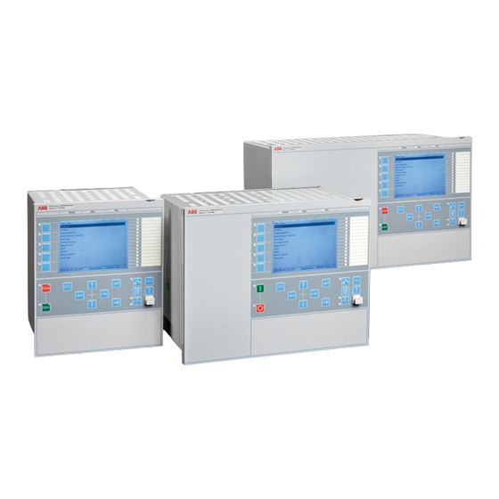
Page 88: Local Hmi
Section 5 1MRK502052-UEN B Local Human-Machine-Interface LHMI Operation principle 5.5.1 Local HMI IEC13000239-2-en.vsd IEC13000239 V2 EN Figure 7: Local human-machine interface The LHMI of the IED contains the following elements: • Keypad • Display (LCD) • LED indicators • Communication port for PCM600 Technical manual... - Page 89 Section 5 1MRK502052-UEN B Local Human-Machine-Interface LHMI The LHMI is used for setting, monitoring and controlling. 5.5.1.1 Display The LHMI includes a graphical monochrome display with a resolution of 320 x 240 pixels. The character size can vary. The amount of characters and rows fitting the view depends on the character size and the view that is shown.
- Page 90 Section 5 1MRK502052-UEN B Local Human-Machine-Interface LHMI • The path shows the current location in the menu structure. If the path is too long to be shown, it is truncated from the beginning, and the truncation is indicated with three dots. •...
-
Page 91: Leds
Section 5 1MRK502052-UEN B Local Human-Machine-Interface LHMI IEC13000281-1-en.vsd GUID-C98D972D-D1D8-4734-B419-161DBC0DC97B V1 EN Figure 10: Function button panel The alarm LED panel shows on request the alarm text labels for the alarm LEDs. Three alarm LED pages are available. IEC13000240-1-en.vsd GUID-5157100F-E8C0-4FAB-B979-FD4A971475E3 V1 EN Figure 11: Alarm LED panel The function button and alarm LED panels are not visible at the same time. -
Page 92: Keypad
Section 5 1MRK502052-UEN B Local Human-Machine-Interface LHMI There are 15 programmable alarm LEDs on the front of the LHMI. Each LED can indicate three states with the colors: green, yellow and red. The alarm texts related to each three-color LED are divided into three pages. 5.5.1.3 Keypad The LHMI keypad contains push-buttons which are used to navigate in different... - Page 93 Section 5 1MRK502052-UEN B Local Human-Machine-Interface LHMI IEC15000157-2-en.vsd IEC15000157 V2 EN Figure 12: LHMI keypad with object control, navigation and command push- buttons and RJ-45 communication port 1...5 Function button Close Open Escape Left Down Right Enter Remote/Local Uplink LED Not in use Multipage Technical manual...
-
Page 94: Led
Section 5 1MRK502052-UEN B Local Human-Machine-Interface LHMI Menu Clear Help Communication port Programmable indication LEDs IED status LEDs 5.5.2 5.5.2.1 Functionality The function blocks LEDGEN and GRP1_LEDx, GRP2_LEDx and GRP3_LEDx (x=1-15) controls and supplies information about the status of the indication LEDs. The input and output signals of the function blocks are configured with PCM600. -
Page 95: Indication Leds
Section 5 1MRK502052-UEN B Local Human-Machine-Interface LHMI The yellow and red status LEDs are configured in the disturbance recorder function, DRPRDRE, by connecting a start or trip signal from the actual function to a BxRBDR binary input function block using the PCM600, and configuring the setting to Off, Start or Trip for that particular signal. - Page 96 Section 5 1MRK502052-UEN B Local Human-Machine-Interface LHMI function button. The function is positive edge triggered, not level triggered. This means that even if the button is continuously pressed, the acknowledgment/reset only affects indications active at the moment when the button is first pressed. •...
- Page 97 Section 5 1MRK502052-UEN B Local Human-Machine-Interface LHMI = No indication = Steady light = Flash = Green = Red = Yellow IEC09000311.vsd IEC09000311 V1 EN Figure 13: Symbols used in the sequence diagrams Sequence 1 (Follow-S) This sequence follows the corresponding input signals all the time with a steady light. It does not react on acknowledgment or reset.
- Page 98 Section 5 1MRK502052-UEN B Local Human-Machine-Interface LHMI signal is not present any more. If the signal is still present after acknowledgment it gets a steady light. Activating signal Acknow. en01000231.vsd IEC01000231 V1 EN Figure 16: Operating Sequence 3 LatchedAck-F-S The sequence described below is valid only if the same function block is used for all three colour LEDs.
- Page 99 Section 5 1MRK502052-UEN B Local Human-Machine-Interface LHMI Activating signal GREEN Activating signal YELLOW Activating signal RED Acknow. IEC09000314-1-en.vsd IEC09000314 V1 EN Figure 18: Operating sequence 3, three colors involved, alternative 1 If an indication with higher priority appears after acknowledgment of a lower priority indication the high priority indication will be shown as not acknowledged according to figure 19.
- Page 100 Section 5 1MRK502052-UEN B Local Human-Machine-Interface LHMI Activating signal Reset IEC01000235_2_en.vsd IEC01000235 V2 EN Figure 20: Operating Sequence 5 LatchedColl-S That means if an indication with higher priority has reset while an indication with lower priority still is active at the time of reset, the LED will change color according to figure21.
- Page 101 Section 5 1MRK502052-UEN B Local Human-Machine-Interface LHMI Disturbance tRestart Activating signal 1 Activating signal 2 LED 1 LED 2 Automatic reset Manual reset IEC01000239_2-en.vsd IEC01000239 V2 EN Figure 22: Operating sequence 6 (LatchedReset-S), two indications within same disturbance Figure shows the timing diagram for a new indication after tRestart time has elapsed.
- Page 102 Section 5 1MRK502052-UEN B Local Human-Machine-Interface LHMI Figure shows the timing diagram when a new indication appears after the first one has reset but before tRestart has elapsed. Disturbance tRestart Activating signal 1 Activating signal 2 LED 1 LED 2 Automatic reset Manual...
-
Page 103: Function Keys
Section 5 1MRK502052-UEN B Local Human-Machine-Interface LHMI Disturbance tRestart Activating signal 1 Activating signal 2 LED 1 LED 2 Automatic reset Manual reset IEC01000242_2_en.vsd IEC01000242 V2 EN Figure 25: Operating sequence 6 (LatchedReset-S), manual reset 5.5.3 Function keys 5.5.3.1 Functionality Local Human-Machine-Interface (LHMI) has five function buttons, directly to the left of the LCD, that can be configured either as menu shortcut or control buttons. - Page 104 Section 5 1MRK502052-UEN B Local Human-Machine-Interface LHMI Operating sequence The operation mode is set individually for each output, either OFF, TOGGLE or PULSED. Setting OFF This mode always sets the outputs to a low value (0). Input value Output value IEC09000330-2-en.vsd IEC09000330 V2 EN Figure 26:...
- Page 105 Section 5 1MRK502052-UEN B Local Human-Machine-Interface LHMI Input value 500ms 500ms 500ms 500ms pulse time pulse time pulse time Output value IEC09000332_2_en.vsd IEC09000332 V2 EN Figure 28: Sequence diagram for setting PULSED Input function All function keys work the same way: When the LHMI is configured so that a certain function button is of type CONTROL, then the corresponding input on this function block becomes active, and will light the yellow function button LED when high.
-
Page 107: Functionality
Section 6 1MRK502052-UEN B Differential protection Section 6 Differential protection Transformer differential protection T2WPDIF and T3WPDIF 6.1.1 Identification Function description IEC 61850 IEC 60617 ANSI/IEEE C37.2 identification identification device number Transformer differential protection, two- T2WPDIF winding 3Id/I SYMBOL-BB V1 EN Transformer differential protection, T3WPDIF three-winding... - Page 108 Section 6 1MRK502052-UEN B Differential protection two-winding power transformer with two circuit breakers and two CT-sets on one xx05000050.vsd side IEC05000050 V1 EN two-winding power transformer with two circuit breakers and two CT-sets on both sides xx05000051.vsd IEC05000051 V1 EN Three-winding applications three-winding power transformer with all...
-
Page 109: Function Block
Section 6 1MRK502052-UEN B Differential protection inrush and CT saturation during external faults. A high set unrestrained differential current protection element is included for a very high speed tripping at high internal fault currents. Included is an sensitive differential protection element based on the theory of negative sequence current component. -
Page 110: Signals
Section 6 1MRK502052-UEN B Differential protection T3WPDIF I3PW1CT1* TRIP I3PW1CT2* TRIPRES I3PW2CT1* TRIPUNRE I3PW2CT2* TRNSUNR I3PW3CT1* TRNSSENS I3PW3CT2* START TAPOLTC1 STL1 TAPOLTC2 STL2 OLTC1AL STL3 OLTC2AL BLK2H BLOCK BLK2HL1 BLKRES BLK2HL2 BLKUNRES BLK2HL3 BLKNSUNR BLK5H BLKNSSEN BLK5HL1 BLK5HL2 BLK5HL3 BLKWAV BLKWAVL1 BLKWAVL2 BLKWAVL3... - Page 111 Section 6 1MRK502052-UEN B Differential protection Table 36: T2WPDIF Output signals Name Type Description TRIP BOOLEAN General, common trip signal TRIPRES BOOLEAN Trip signal from restrained differential protection TRIPUNRE BOOLEAN Trip signal from unrestrained differential protection TRNSUNR BOOLEAN Trip signal from unrestr. neg. seq. diff. protection TRNSSENS BOOLEAN Trip signal from sensitive neg.
- Page 112 Section 6 1MRK502052-UEN B Differential protection Table 37: T3WPDIF Input signals Name Type Default Description I3PW1CT1 GROUP Three phase winding primary CT1 SIGNAL I3PW1CT2 GROUP Three phase winding primary CT2 SIGNAL I3PW2CT1 GROUP Three phase winding secondary CT1 SIGNAL I3PW2CT2 GROUP Three phase winding secondary CT2 SIGNAL...
-
Page 113: Settings
Section 6 1MRK502052-UEN B Differential protection Name Type Description BLK5HL1 BOOLEAN Fifth harmonic block signal, phase L1 BLK5HL2 BOOLEAN Fifth harmonic block signal, phase L2 BLK5HL3 BOOLEAN Fifth harmonic block signal, phase L3 BLKWAV BOOLEAN Common block signal, waveform criterion, from any phase BLKWAVL1 BOOLEAN... - Page 114 Section 6 1MRK502052-UEN B Differential protection Name Values (Range) Unit Step Default Description CrossBlockEn Operation Off/On for cross-block logic between phases NegSeqDiffEn Operation Off/On for neg. seq. differential protections IMinNegSeq 0.02 - 0.20 0.01 0.04 Neg. seq. curr. must be higher than this level to be used NegSeqROA 30.0 - 120.0...
- Page 115 Section 6 1MRK502052-UEN B Differential protection Name Values (Range) Unit Step Default Description ClockNumberW2 0 [0 deg] 0 [0 deg] Phase displacement between W2 & 1 [30 deg lag] W1=HV winding, hour notation 2 [60 deg lag] 3 [90 deg lag] 4 [120 deg lag] 5 [150 deg lag] 6 [180 deg]...
- Page 116 Section 6 1MRK502052-UEN B Differential protection Name Values (Range) Unit Step Default Description SOTFMode Operation mode for switch onto fault feature IdMin 0.05 - 0.60 0.01 0.30 Section1 sensitivity, multi. of base curr, usually W1 curr. IdUnre 1.00 - 100.00 0.01 10.00 Unrestr.
- Page 117 Section 6 1MRK502052-UEN B Differential protection Name Values (Range) Unit Step Default Description ConnectTypeW2 WYE (Y) WYE (Y) Connection type of winding 2: Y-wye or D- Delta (D) delta ConnectTypeW3 WYE (Y) Delta (D) Connection type of winding 3: Y-wye or D- Delta (D) delta ClockNumberW2...
-
Page 118: Monitored Data
Section 6 1MRK502052-UEN B Differential protection Name Values (Range) Unit Step Default Description LocationOLTC1 Not Used Not Used Transformer winding where OLTC1 is Winding 1 (W1) located Winding 2 (W2) Winding 3 (W3) LowTapPosOLTC1 0 - 10 OLTC1 lowest tap position designation (e.g. -
Page 119: Operation Principle
Section 6 1MRK502052-UEN B Differential protection Name Type Values (Range) Unit Description IDL3MAG REAL Magnitude of fundamental freq. diff. current, phase L3 IBIAS REAL Magnitude of the bias current, which is common to all phases IDNSMAG REAL Magnitude of the negative sequence differential current Table 46:... -
Page 120: Function Calculation Principles
Section 6 1MRK502052-UEN B Differential protection en05000186.vsd IEC05000186 V1 EN Figure 32: Typical CT location and definition of positive current direction Even in a healthy power transformer, the currents are generally not equal when they flow through it. This is due to the ratio of the number of turns of the windings and the connection group of the protected transformer. - Page 121 Section 6 1MRK502052-UEN B Differential protection proportional bias, which makes the protection operate for a certain percentage differential current related to the current through the transformer. This stabilizes the protection under through fault conditions while still permitting the system to have good basic sensitivity.
- Page 122 Section 6 1MRK502052-UEN B Differential protection é ù é ù é ù é ù 1_ 1 Un W Un W ê ú ê ú ê ú ê ú × × × × × A IL 2 _ 1 ê ú ê...
- Page 123 Section 6 1MRK502052-UEN B Differential protection When the end user enters all these parameters, transformer differential function automatically calculates the matrix coefficients. During this calculations the following rules are used: For the phase reference, the first winding with set star (Y) connection is always used. For example, if the power transformer is a Yd1 power transformer, the HV winding (Y) is taken as the phase reference winding.
- Page 124 Section 6 1MRK502052-UEN B Differential protection Table 47: Matrices for differential current calculation Matrix with Zero Sequence Matrix with Zero Sequence Reduction set to On Reduction set to Off Matrix for Reference Winding é ù é ù 1 0 0 ê...
- Page 125 Section 6 1MRK502052-UEN B Differential protection Matrix with Zero Sequence Matrix with Zero Sequence Reduction set to On Reduction set to Off Matrix for winding with 120° é ù é ù 0 1 0 leading ê ú ê ú × - 0 0 1 ê...
- Page 126 Section 6 1MRK502052-UEN B Differential protection IL1_W1 is the fundamental frequency phase current in phase L1 on the W1 side IL2_W1 is the fundamental frequency phase current in phase L2 on the W1 side IL3_W1 is the fundamental frequency phase current in phase L3 on the W1 side IL1_W2 is the fundamental frequency phase current in phase L1 on the W2 side IL2_W2...
- Page 127 Section 6 1MRK502052-UEN B Differential protection corresponding value for Ur_W1 will be calculated and used in the above mentioned equations. By doing this, complete on-line compensation for load tap changer movement is achieved. Differential protection will be ideally balanced for every load tap changer position and no false differential current will appear irrespective of actual load tap changer position.
- Page 128 Section 6 1MRK502052-UEN B Differential protection (restrain) current for all three phases. This "maximum principle" makes the differential protection more secure, with less risk to operate for external faults and in the same time brings more meaning to the breakpoint settings of the operate - restrain characteristic.
- Page 129 Section 6 1MRK502052-UEN B Differential protection quantities, but zero sequence currents can flow in the earthed star- connected winding. In such cases, an external earth-fault on the star-side causes zero sequence current to flow on the star-side of the power transformer, but not on the other side. This results in false differential currents - consisting exclusively of the zero sequence currents.
- Page 130 Section 6 1MRK502052-UEN B Differential protection IdMin EndSection1 EndSection2 SlopeSection2 SlopeSection3 operate current [ times IBase ] Operate unconditionally UnrestrainedLimit Operate conditionally Section 1 Section 2 Section 3 SlopeSection3 IdMin SlopeSection2 Restrain EndSection1 restrain current [ times IBase ] EndSection2 en05000187-2.vsd IEC05000187 V2 EN Figure 33:...
- Page 131 Section 6 1MRK502052-UEN B Differential protection Section 1: This is the most sensitive part on the characteristic. In section 1, normal currents flow through the protected circuit and its current transformers, and risk for higher false differential currents is relatively low. An un-compensated on-load tap- changer is a typical reason for existence of the false differential currents in this section.
- Page 132 Section 6 1MRK502052-UEN B Differential protection é ù é ù é ù é ù é ù INS W INS W ê ú ê ú ê ú ê ú ê ú Ur W × × × × × × × a INS W a INS W ê...
- Page 133 Section 6 1MRK502052-UEN B Differential protection current from the W2 side compensated for eventual power transformer phase shift and transferred to the power transformer W1 side. These negative sequence current contributions are phasors, which are further used in directional comparisons, to characterize a fault as internal or external.
- Page 134 Section 6 1MRK502052-UEN B Differential protection 90 deg 120 deg If one or the Internal/external other of fault boundary currents is too low, then no measurement NegSeqROA is done, and (Relay 120 degrees Operate is mapped Angle) 180 deg 0 deg IMinNegSeq External Internal...
- Page 135 Section 6 1MRK502052-UEN B Differential protection • If the negative sequence current contributions from the W1 and the W2 sides are in phase, the fault is internal (that is, both phasors are within protected zone) • If the negative sequence currents contributions from W1 and W2 sides are 180 degrees out of phase, the fault is external (that is, W1 phasors is outside protected zone) For example, for any unsymmetrical external fault, ideally the respective negative...
- Page 136 Section 6 1MRK502052-UEN B Differential protection different negative sequence source impedance angles on the W1 and W2 sides of the protected power transformer, it may differ somewhat from the ideal zero value. However, during heavy faults, CT saturation might cause the measured phase angle to differ from 180 degrees for an external, and from 0 degrees for an internal fault.
- Page 137 Section 6 1MRK502052-UEN B Differential protection because one or more of the fundamental frequency differential currents entered the operate region on the operate - restrain characteristic. So, this protection is not independent of the traditional restrained differential protection - it is activated after the first start signal has been placed.
- Page 138 Section 6 1MRK502052-UEN B Differential protection used for these calculations. The only difference is that the matrix algorithm is fed by instantaneous values of currents, that is, samples. Harmonic and waveform block criteria The two block criteria are the harmonic restrain and the waveform restrain. These two criteria have the power to block a trip command by the traditional differential protection, which produces start signals by applying the differential currents, and the bias current, to the operate - restrain characteristic.
- Page 139 Section 6 1MRK502052-UEN B Differential protection IEC05000343 V1 EN Figure 37: Inrush currents to a transformer as seen by a protective IED. Typical is a high amount of the 2 harmonic, and intervals of low current, and low rate-of-change of current within each period. Cross-blocking between phases The basic definition of the cross-blocking is that one of the three phases can block operation (that is, tripping) of the other two phases due to the harmonic pollution of the...
- Page 140 Section 6 1MRK502052-UEN B Differential protection waveblock criterion will temporarily disable the second harmonic blocking feature of the differential protection function. This consequently ensures fast operation of the transformer differential function for a switch onto a fault condition. It shall be noted that this feature is only active during initial power transformer energizing, under the first 50 ms.
-
Page 141: Logic Diagram
Section 6 1MRK502052-UEN B Differential protection If an open CT is detected and the output OPENCT set to 1, then all the differential functions are blocked, except the unrestrained (instantaneous) differential. An alarm signal is also produced after a settable delay (tOCTAlarmDelay) to report to operational personnel for quick remedy actions once the open CT is detected. - Page 142 Section 6 1MRK502052-UEN B Differential protection Differential function Trafo Data IDL1 Instantaneous (sample based) Differential current, phase L1 IDL2 Instantaneous (sample based) Differential current, phase L2 IDL3 Instantaneous (sample based) Differential current, phase L3 IDNSMAG Negative sequence diff current & NS current contribution from individual windings IDL1MAG Fundamental frequency (phasor...
- Page 143 Section 6 1MRK502052-UEN B Differential protection Instantaneous values of currents (samples) from the HV, and LV sides for two- winding power transformers, and from the HV, the first LV, and the second LV side for three-winding power transformers. Currents from all power transformer sides expressed as fundamental frequency phasors with their real and imaginary parts.
-
Page 144: Signals
Section 6 1MRK502052-UEN B Differential protection Internal/ EXTFAULT Neg.Seq. Diff External INTFAULT Current Fault discrimin Contributions ator TRNSSENS & OpNegSeqDiff=On IBIAS b>a Constant & STL1 STL2 >1 STL3 IEC05000167-2-en.vsd IEC05000167-TIFF V2 EN Figure 40: Transformer differential protection simplified logic diagram for external/internal fault discriminator TRIPRESL1 TRIPRESL2... - Page 145 Section 6 1MRK502052-UEN B Differential protection STL1 STL2 START STL3 BLK2HL1 BLK2HL2 BLK2H BLK2HL3 BLK5HL1 BLK5HL2 BLK5H BLK5HL3 BLKWAVL1 BLKWAVL2 BLKWAV BLKWAVL3 IEC05000279-2-en.vsd IEC05000279-TIFF V2 EN Figure 42: Transformer differential protection internal grouping of logical signals Logic in figures 39, 40, can be summarized as follows: The three fundamental frequency differential currents are applied in a phase-wise manner to two limits.
-
Page 146: Technical Data
Section 6 1MRK502052-UEN B Differential protection blocks with the text inside: 2nd Harmonic; Wave block and 5th Harmonic). If there is less harmonic pollution. than allowed by the settings I2/I1Ratio, and I5/ I1Ratio, (then the outputs from the blocks 2nd harmonic and 5th harmonic is 0) then it is assumed that a minor simultaneous internal fault must have occurred. -
Page 147: Identification
Section 6 1MRK502052-UEN B Differential protection Function Range or value Accuracy Connection type for each of the Y or D windings Phase displacement between high 0–11 voltage winding, W1 and each of the windings, W2 and W3. Hour notation *Operate time at 0 to 10 x IdMin, Min. -
Page 148: Function Block
Section 6 1MRK502052-UEN B Differential protection HZPDIF can be used to protect generator stator windings, tee-feeders or busbars, reactors, motors, auto-transformers, capacitor banks and so on. One such function block is used for a high-impedance restricted earth fault protection. Three such function blocks are used to form three-phase, phase-segregated differential protection. -
Page 149: Monitored Data
Section 6 1MRK502052-UEN B Differential protection 6.2.6 Monitored data Table 52: HZPDIF Monitored data Name Type Values (Range) Unit Description MEASVOLT REAL Measured RMS voltage on CT secondary side 6.2.7 Operation principle High impedance protection system is a simple technique which requires that all CTs, used in the protection scheme, have relatively high knee point voltage, similar magnetizing characteristic and the same ratio. -
Page 150: Logic Diagram
Section 6 1MRK502052-UEN B Differential protection It is of utmost importance to insure that only one earthing point exists in such protection scheme. shows the setting (stabilizing) resistor RS. shows the over-current measuring element. The series connection of stabilizing resistor and over-current element is designated as measuring branch. -
Page 151: Technical Data
Section 6 1MRK502052-UEN B Differential protection The voltage waveform is then filtered in order to get its RMS value. Note that used filtering is designed in such a way that it ensures complete removal of the DC current component which may be present in the primary fault current. The voltage RMS value is then compared with set Alarm and Trip thresholds. -
Page 152: Generator Differential Protection Genpdif
Section 6 1MRK502052-UEN B Differential protection Generator differential protection GENPDIF 6.3.1 Identification Function description IEC 61850 IEC 60617 ANSI/IEEE C37.2 identification identification device number Generator differential protection GENPDIF > SYMBOL-NN V1 EN 6.3.2 Functionality Short circuit between the phases of the stator windings causes normally very large fault currents. -
Page 153: Signals
Section 6 1MRK502052-UEN B Differential protection 6.3.3 Function block GENPDIF I3PNCT1* TRIP I3PNCT2* TRIPRES I3PTCT1* TRIPUNRE I3PTCT2* TRNSUNR BLOCK TRNSSENS BLKRES START BLKUNRES STL1 BLKNSUNR STL2 BLKNSSEN STL3 DESENSIT BLKH OPENCT OPENCTAL IDL1 IDL2 IDL3 IDNSMAG IBIAS IEC11000212-1-en.vsd IEC11000212 V1 EN Figure 47: GENPDIF function block 6.3.4... -
Page 154: Settings
Section 6 1MRK502052-UEN B Differential protection Table 55: GENPDIF Output signals Name Type Description TRIP BOOLEAN General, common trip signal TRIPRES BOOLEAN Trip signal from restrained differential protection TRIPUNRE BOOLEAN Trip signal from unrestrained differential protection TRNSUNR BOOLEAN Trip signal from unrestr. neg. seq. diff. protection TRNSSENS BOOLEAN Trip signal from sensitive neg. - Page 155 Section 6 1MRK502052-UEN B Differential protection Table 57: GENPDIF Group settings (advanced) Name Values (Range) Unit Step Default Description EndSection1 0.20 - 1.50 0.01 1.25 End of section 1, multiple of generator rated current EndSection2 1.00 - 10.00 0.01 3.00 End of section 2, multiple of generator rated current SlopeSection2...
-
Page 156: Monitored Data
Section 6 1MRK502052-UEN B Differential protection 6.3.6 Monitored data Table 59: GENPDIF Monitored data Name Type Values (Range) Unit Description IDL1MAG REAL Fund. freq. differential current, phase L1; in primary A IDL2MAG REAL Fund. freq. differential current, phase L2; in primary A IDL3MAG REAL... -
Page 157: Function Calculation Principles
Section 6 1MRK502052-UEN B Differential protection components than it is to calculate zero-sequence components. Diversity of operation principles integrated in the same protection function enhances the overall performance without a significant increase in cost. A novelty in GENPDIF, namely the negative-sequence-current-based internal- external fault discriminator, is used advantageously in order to determine whether a fault is internal or external. - Page 158 Section 6 1MRK502052-UEN B Differential protection One common fundamental frequency bias current is used. The bias current is the magnitude of the highest measured current in the protected circuit. The bias current is not allowed to drop instantaneously, instead, it decays exponentially with a predefined time constant.
- Page 159 Section 6 1MRK502052-UEN B Differential protection Generator differential protection GENPDIF function uses two mutually independent characteristics to which magnitudes of the three fundamental frequency RMS differential currents are compared at each execution of the differential protection function. These two characteristics divide, each of them independently, the operate current –...
- Page 160 Section 6 1MRK502052-UEN B Differential protection currents in this section can be tolerances of the current transformers used on both sides of the protected generator. Slope in section 1 is always zero percent. Normally, with the protected machine at rated load, the restrain, bias current will be around 1 p.u., that is, equal to the machine rated current.
- Page 161 Section 6 1MRK502052-UEN B Differential protection operate current [ times IBase ] Operate unconditionally UnrestrainedLimit Operate conditionally Section 1 Section 2 Section 3 SlopeSection3 TempIdMin IdMin SlopeSection2 Restrain EndSection1 restrain current [ times IBase ] EndSection2 en06000637.vsd IEC06000637 V2 EN Figure 52: Operate-restrain characteristic GENPDIF can also be temporarily ‘desensitized’...
-
Page 162: Supplementary Criteria
Section 6 1MRK502052-UEN B Differential protection 6.3.7.3 Supplementary criteria To relieve the burden of constructing an exact optimal operate-restrain characteristic, two special features supplement the basic stabilized differential protection function, making Generator differential protection GENPDIF a very reliable one. The supplementary criteria are: •... - Page 163 Section 6 1MRK502052-UEN B Differential protection If the two negative sequence currents flow in opposite directions, the fault is external. • Under external fault condition, the relative angle is theoretically equal to 180°. Under internal fault condition, the angle is ideally 0°, but due to possible different negative-sequence impedance angles on both sides of the internal fault, it may differ somewhat from 0°.
- Page 164 Section 6 1MRK502052-UEN B Differential protection 90 deg 120 deg NegSeqROA Angle could not be (Relay Operate Angle) measured. One or both currents too small Internal fault region 180 deg 0 deg IminNegSeq External fault region Internal / external fault boundary.
-
Page 165: Harmonic Restrain
Section 6 1MRK502052-UEN B Differential protection 6.3.7.4 Harmonic restrain Harmonic restrain is the classical restrain method traditionally used with power transformer differential protections. The goal there was to prevent an unwanted trip command due to magnetizing inrush currents at switching operations, due to magnetizing currents at over-voltages, or external faults. - Page 166 Section 6 1MRK502052-UEN B Differential protection the unwanted trip cannot always be prevented. Still, the information about what was the cause of the open CT secondary circuit, is vital. The principle applied to detect an open CT is a simple pattern recognition method, similar to the waveform check used by the Power transformer differential protection in order to detect the magnetizing inrush condition.
-
Page 167: Cross-Block Logic Scheme
Section 6 1MRK502052-UEN B Differential protection the open CT condition has been detected, it can be reset automatically within the differential function. It is not possible to externally reset an open CT condition. To reset the open CT circuit alarm automatically, the following conditions must be fulfilled: •... - Page 168 Section 6 1MRK502052-UEN B Differential protection TRIP Signals Start Phasors IL1N, IL2N,IL3N Magnitude phase Idiff and Ibias Diff.prot. selective Calculation characteristic Idiff and Ibias Phasors IL1T, IL2T,IL3T START Signals BLOCK Signals Samples IL1N, IL2N,IL3N Harm. INTFAULT Hamonic Calculation Samples Idiff Block Start and instantaneous...
- Page 169 Section 6 1MRK502052-UEN B Differential protection BLKUNRES IdUnre TRIPUNREL1 b>a IDL1MAG IBIAS STL1 BLOCK BLKRES INTFAULT TRIPRESL1 2nd and Harmonic Cross Block from L2 or L3 OpCrossBlock=On en07000020.vsd IEC07000020 V2 EN Figure 55: Generator differential logic diagram 1 Internal/ Neg.Seq. Diff External INTFAULT Current...
-
Page 170: Technical Data
Section 6 1MRK502052-UEN B Differential protection STL1 STL2 START STL3 BLKHL1 BLKHL2 BLKH BLKHL3 en07000022.vsd IEC07000022 V1 EN Figure 57: Generator differential logic diagram 3 TRIPRESL1 TRIPRESL2 TRIPRES TRIPRESL3 TRIPUNREL1 TRIPUNREL2 TRIPUNRE TRIPUNREL3 TRIP TRNSSENS TRNSUNR en07000023.vsd IEC07000023 V1 EN Figure 58: Generator differential logic diagram 4 6.3.8... -
Page 171: Functionality
Section 6 1MRK502052-UEN B Differential protection Function Range or value Accuracy Reset time at 5 to 0 x IdUnre Min. = 15 ms unrestrained function Max. = 30 ms Critical impulse time, unrestrained function 2 ms typically at 0 to 5 x IdUnre Impulse margin time unrestrained function 10 ms typically... -
Page 172: Signals
Section 6 1MRK502052-UEN B Differential protection YNdx Autotransformer The most typical application The most complicated application - autotransformer IEC05000058-2-en.vsd IEC05000058-2 V1 EN Figure 59: Examples of applications of the REFPDIF 6.4.3 Function block REFPDIF I3P* TRIP I3PW1CT1* START I3PW1CT2* DIROK I3PW2CT1* BLK2H I3PW2CT2*... -
Page 173: Settings
Section 6 1MRK502052-UEN B Differential protection Table 62: REFPDIF Output signals Name Type Description TRIP BOOLEAN Trip by restricted earth fault protection function START BOOLEAN Start by restricted earth fault protection function DIROK BOOLEAN Directional Criteria has operated for internal fault BLK2H BOOLEAN Block due to 2-nd harmonic... -
Page 174: Operation Principle
Section 6 1MRK502052-UEN B Differential protection 6.4.6 Monitored data Table 66: REFPDIF Monitored data Name Type Values (Range) Unit Description IRES REAL Magnitude of fund. freq. residual current REAL Magnitude of fund. freq. neutral current IBIAS REAL Magnitude of the bias current IDIFF REAL... - Page 175 Section 6 1MRK502052-UEN B Differential protection These three zone of protection zero-sequence currents are not measured Power system 3Izs1 Current in the neutral (measured as I ) serves = 3I as a directional reference = 3Izs1 3Izs1 Ifault because it has the same (Summation in the IED) direction for both internal Return path through...
-
Page 176: Restricted Earth-Fault Protection, Low Impedance Differential Protection
However, on the secondary CT sides of the current transformers, they will be approximately in phase if the current transformers are oriented as in Figure 59, which is the orientation recommended by ABB. The magnitudes of the two currents may be different, dependent on the magnitudes of zero sequence impedances of both sides. - Page 177 Section 6 1MRK502052-UEN B Differential protection REFPDIF is not sensitive to inrush and overexcitation currents. The only danger is an eventual current transformer saturation. REFPDIF has only one operate-bias characteristic, which is described in the table and shown in Figure 63. Table 67: Data of the operate-bias characteristic of REFPDIF Default sensitivity Idmin...
-
Page 178: Calculation Of Differential Current And Bias Current
Section 6 1MRK502052-UEN B Differential protection 6.4.7.3 Calculation of differential current and bias current The differential current (operate current), as a fundamental frequency phasor, is calculated as (with designations as in Figure and Figure 62): Idiff (Equation 29) EQUATION1533 V1 EN where: is current in the power transformer neutral as a fundamental frequency phasor. -
Page 179: Detection Of External Earth Faults
Section 6 1MRK502052-UEN B Differential protection × current[4] = max (I3PW2CT2) CTFactorSec2 (Equation 33) EQUATION1529 V1 EN current[5] = IN (Equation 34) EQUATION1530 V1 EN The bias current is thus generally equal to none of the input currents. If all primary ratings of the CTs were equal to IBase, then the bias current would be equal to the highest current in Amperes. - Page 180 Section 6 1MRK502052-UEN B Differential protection (REFPDIF) must remain stable during an external fault, and immediately after the fault has been cleared by some other protection. For an external earth faults with no CT saturation, the residual current in the lines ) and the neutral current (I in Figure 61) are theoretically equal in magnitude and are 180 degrees out-of-phase.
-
Page 181: Algorithm Of The Restricted Earth-Fault Protection
Section 6 1MRK502052-UEN B Differential protection 6.4.7.5 Algorithm of the restricted earth-fault protection Check if current in the neutral Ineutral (IN) is less than 50% of the base sensitivity Idmin. If yes, only service values are calculated, then REFPDIF algorithm is not used. - Page 182 Section 6 1MRK502052-UEN B Differential protection Function Range or value Accuracy Directional characteristic Fixed 180 degrees or ± 60 to ± 90 ± 2.0 degrees degrees Operate time, trip at 0 to 10 x Min = 15 ms IdMin Max = 30 ms Reset time, trip at 10 to 0 x IdMin Min = 15 ms Max = 30 ms...
-
Page 183: Functionality
Section 7 1MRK502052-UEN B Impedance protection Section 7 Impedance protection Full-scheme distance measuring, Mho characteristic ZMHPDIS 7.1.1 Identification Function description IEC 61850 IEC 60617 identification ANSI/IEEE identification C37.2 device number Full-scheme distance protection, mho ZMHPDIS characteristic S00346 V1 EN 7.1.2 Functionality The numerical mho line distance protection is a, up to four zone full scheme protection for back-up detection of short circuit and earth faults. -
Page 184: Function Block
Section 7 1MRK502052-UEN B Impedance protection 7.1.3 Function block ZMHPDIS I3P* TRIP U3P* TRL1 CURR_INP* TRL2 VOLT_INP* TRL3 POL_VOLT* TRPE BLOCK TRPP BLKZ START BLKZMTD STL1 BLKHSIR STL2 BLKTRIP STL3 BLKPE STPE BLKPP STPP EXTNST STTIMER INTRNST DIRCND STCND* LDCND IEC06000423-2-en.vsd IEC06000423 V3 EN Figure 64:... -
Page 185: Settings
Section 7 1MRK502052-UEN B Impedance protection Table 70: ZMHPDIS Output signals Name Type Description TRIP BOOLEAN Trip General TRL1 BOOLEAN Trip phase L1 TRL2 BOOLEAN Trip phase L2 TRL3 BOOLEAN Trip phase L3 TRPE BOOLEAN Trip phase-to-earth TRPP BOOLEAN Trip phase-to-phase START BOOLEAN Start General... -
Page 186: Operation Principle
Section 7 1MRK502052-UEN B Impedance protection Name Values (Range) Unit Step Default Description ZRevPE 0.005 - 3000.000 Ohm/p 0.001 30.000 Reverse reach of the phase to earth loop(magnitude) 0.000 - 60.000 0.001 0.000 Delay time for operation of phase to earth elements IMinOpPE 10 - 30... -
Page 187: Impedance Characteristic
Section 7 1MRK502052-UEN B Impedance protection 7.1.6.2 Impedance characteristic The Mho distance function ZMHPDIS is present with four instances so that four separate zones could be designed. Each instance can be selected to be either forward or reverse with positive sequence polarized mho characteristic; alternatively self polarized offset mho characteristics is also available. -
Page 188: Basic Operation Characteristics
Section 7 1MRK502052-UEN B Impedance protection identification with load encroachment for mho function FMPSPDIS, where also the relevant settings can be found. Information about the load encroachment from FMPSPDIS to the zone measurement is given in binary format to the input signal LDCND. - Page 189 Section 7 1MRK502052-UEN B Impedance protection Compensation for earth -return path for faults involving earth is done by setting the parameter KN and KNAng where KN is the magnitude of the earth -return path and KNAng is the argument of the earth-return path. ×...
-
Page 190: Theory Of Operation
Section 7 1MRK502052-UEN B Impedance protection The function can be blocked in the following ways: • activating of input BLOCK blocks the whole function • activating of the input BLKZ (fuse failure) blocks all output signals • activating of the input BLKZMTD blocks the delta based time domain algorithm •... - Page 191 Section 7 1MRK502052-UEN B Impedance protection where is the voltage vector difference between phases L1 and L2 L1L2 EQUATION1790 V2 is the current vector difference between phases L1 and L2 L1L2 EQUATION1791 V2 is the positive sequence impedance setting for phase-to-phase fault is the polarizing voltage The polarized voltage consists of 100% memorized positive sequence voltage (UL1L2 for phase L1 to L2 fault).
- Page 192 Section 7 1MRK502052-UEN B Impedance protection The condition for operation at phase-to-phase fault is that the angle β between the two compensated voltages Ucomp1 and Ucomp2 is greater than or equal to 90° (figure 67). The angle will be 90° for fault location on the boundary of the circle. The angle β...
- Page 193 Section 7 1MRK502052-UEN B Impedance protection voltage and the current must lie between the blinders in second quadrant and fourth quadrant. See figure 68. Operation occurs if 90≤β≤270 and ArgDir≤φ≤ArgNegRes. where ArgDir is the setting parameter for directional line in fourth quadrant in the directional element, ZDMRDIR.
- Page 194 Section 7 1MRK502052-UEN B Impedance protection ArgNegRes ϕ IL1L2 ArgDir UL1L2 ZRevPP en06000469.eps IEC06000469 V1 EN Figure 69: Operation characteristic for reverse phase L1-to-L2 fault Phase-to-earth fault The measuring of earth faults uses earth-return compensation applied in a conventional way. The compensation voltage is derived by considering the influence from the earth-return path.
- Page 195 Section 7 1MRK502052-UEN B Impedance protection × Ucomp loop (Equation 39) EQUATION1793 V1 EN where is the polarizing voltage (memorized UL1 for Phase L1-to- earth fault) is the loop impedance, which in general terms can be expressed as loop × Z +ZN where is the positive sequence impedance of the line (Ohm/phase)
- Page 196 Section 7 1MRK502052-UEN B Impedance protection L1· IL1·ZN comp ß • loop ·ZPE Upol ·R IL1 (Ref) en06000472_2.vsd IEC06000472 V2 EN Figure 70: Simplified offset mho characteristic and vector diagram for phase L1- to-earth fault Operation occurs if 90≤β≤270. Offset mho The characteristic for offset mho at earth fault is a circle containing the two vectors from the origin ZPE and ZRevPE where ZPE and ZrevPE are the setting reach for the positive sequence impedance in forward respective reverse direction.
- Page 197 Section 7 1MRK502052-UEN B Impedance protection • • comp1 • ß ZRevPE comp • • L1L2 • en 06000465 .vsd IEC06000465 V1 EN Figure 71: Simplified offset mho characteristic and voltage vector for phase L1- to-earth fault Operation occurs if 90≤β≤270. Offset mho, forward direction In the same way as for phase-to-phase fault, selection of forward direction of offset mho will introduce an extra criterion for operation.
- Page 198 Section 7 1MRK502052-UEN B Impedance protection ArgNegRes IL1·R ArgDir en 06000466 .vsd IEC06000466 V1 EN Figure 72: Simplified characteristic for offset mho in forward direction for L1-to- earth fault Offset mho, reverse direction In the same way as for offset in forward direction, the selection of offset mho in reverse direction will introduce an extra criterion for operation compare to the normal offset mho.
-
Page 199: Simplified Logic Diagrams
Section 7 1MRK502052-UEN B Impedance protection ArgNegRes ϕ IL 1 ArgDir ZRevPE en06000470.eps IEC06000470 V1 EN Figure 73: Simplified characteristic for offset mho in reverse direction for L1-to- earth fault 7.1.6.5 Simplified logic diagrams Distance protection zones The design of the distance protection zones are presented for all measuring loops: phase-to-earth as well as phase-to-phase. - Page 200 Section 7 1MRK502052-UEN B Impedance protection are converted within the zone measuring function into corresponding boolean expressions for each condition separately. Input signal STCND is connected from FMPSPDIS function output signal STCNDPHS. The input signal DIRCND is used to give condition for directionality for the distance measuring zones.
- Page 201 Section 7 1MRK502052-UEN B Impedance protection Release STPE STL1N STL1 STL2N STL3N STL2 STL1L2 STL2L3 STL3 STL3L1 START STPP IEC11000217-1-en.vsd IEC11000217 V1 EN Figure 75: Composition of starting signals Tripping conditions for the distance protection zone one are symbolically presented in figure 76.
- Page 202 Section 7 1MRK502052-UEN B Impedance protection Timer tPP=On STPP Timer tPE=On STPE 15ms TRIP BLKTRIP TRL1 STL1 TRL2 STL2 TRL3 STL3 IEC11000218-1-en.vsd IEC11000218 V1 EN Figure 76: Tripping logic for the distance protection zone Zone timer logic for the distance protection is symbolically presented in figure 77. STPE BLOCK TRPE...
-
Page 203: Functionality
Section 7 1MRK502052-UEN B Impedance protection 7.1.7 Technical data Table 74: ZMHPDIS technical data Function Range or value Accuracy Number of zones, Ph-E Max 4 with selectable direction Minimum operate current (10–30)% of IBase Positive sequence impedance, (0.005–3000.000) W/phase ± 2.0% static accuracy Ph-E loop Conditions: Voltage range: (0.1-1.1) x U... -
Page 204: Signals
Section 7 1MRK502052-UEN B Impedance protection 7.2.3 Function block ZDMRDIR I3P* DIR_CURR U3P* DIR_VOLT DIR_POL STFW STRV STDIRCND IEC06000422_2_en.vsd IEC06000422 V2 EN Figure 78: ZDMRDIR function block 7.2.4 Signals Table 75: ZDMRDIR Input signals Name Type Default Description GROUP Group signal for current input SIGNAL GROUP Group signal for voltage input... -
Page 205: Settings
Section 7 1MRK502052-UEN B Impedance protection Table 78: ZDARDIR Output signals Name Type Description STFWPE BOOLEAN Forward start signal from phase-to-ground directional element STRVPE BOOLEAN Reverse start signal from phase-to-ground directional element DIREFCND INTEGER Start direction Binary coded 7.2.5 Settings Table 79: ZDMRDIR Group settings (basic) Name... -
Page 206: Monitored Data
Section 7 1MRK502052-UEN B Impedance protection Table 82: ZDARDIR Group settings (advanced) Name Values (Range) Unit Step Default Description AngleOp 90 - 180 Operation sector angle Kmag 0.50 - 3000.00 0.01 40.00 Boost-factor in -U0comp and -U2comp polarization Table 83: ZDARDIR Non group settings (basic) Name Values (Range) - Page 207 Section 7 1MRK502052-UEN B Impedance protection × × 0.85 U1 0.15 U1 < < ArgDir arg L1L 2 L1L 2M ArgNeg Re s L1L 2 (Equation 43) EQUATION1619 V1 EN Where: ArgDir Setting for the lower boundary of the forward directional characteristic, by default set to 15 (= -15 degrees) ArgNegRes Setting for the upper boundary of the forward directional characteristic, by default set to...
- Page 208 Section 7 1MRK502052-UEN B Impedance protection Zset reach point ArgNegRes -ArgDir en06000416.vsd IEC06000416 V1 EN Figure 79: Setting angles for discrimination of forward fault The reverse directional characteristic is equal to the forward characteristic rotated by 180 degrees. The code built up for release of the measuring fault loops is as follows: STDIRCND = L1N*1 + L2N*2 + L3N*4 + L1L2*8 + L2L3*16 + L3L1*32 Example: If only L1Nstart, the value is 1, if start in L1N and L3N are detected, the value is 1+4=5.
-
Page 209: High Speed Distance Protection Zmfpdis
Section 7 1MRK502052-UEN B Impedance protection The Directional impedance element for mho characteristic (ZDMRDIR) function has the following output signals: The STDIRCND output provides an integer signal that depends on the evaluation and is derived from a binary coded signal as follows: bit 11 bit 10 bit 9... - Page 210 Section 7 1MRK502052-UEN B Impedance protection The ZMFPDIS function is a six zone full scheme protection with three fault loops for phase-to-phase faults and three fault loops for phase-to-earth faults for each of the independent zones, which makes the function suitable in applications with single- phase autoreclosing.
-
Page 211: Signals
Section 7 1MRK502052-UEN B Impedance protection 7.3.3 Function block ZMFPDIS I3P* TRIPZ1 U3P* TRL1Z1 BLOCK TRL2Z1 VTSZ TRL3Z1 BLKZ1 TRIPZ2 BLKZ2 TRL1Z2 BLKZ3 TRL2Z2 BLKZ4 TRL3Z2 BLKZ5 TRIPZ3 BLKZRV TRIPZ4 BLKTRZ1 TRIPZ5 BLKTRZ2 TRIPZRV BLKTRZ3 STARTZ1 BLKTRZ4 STNDZ1 BLKTRZ5 STARTZ2 BLKTRZRV STL1Z2 STL2Z2... - Page 212 Section 7 1MRK502052-UEN B Impedance protection Name Type Default Description BLKZ1 BOOLEAN Resets all outputs and internal timers of zone 1 BLKZ2 BOOLEAN Resets all outputs and internal timers of zone 2 BLKZ3 BOOLEAN Resets all outputs and internal timers of zone 3 BLKZ4 BOOLEAN Resets all outputs and internal timers of zone 4...
- Page 213 Section 7 1MRK502052-UEN B Impedance protection Name Type Description STL3Z2 BOOLEAN Start in phase L3 from zone 2 - forward direction STNDZ2 BOOLEAN Start in any phase or phases from zone 2 - any direction STARTZ3 BOOLEAN Start in any phase or phases from zone 3 - zone direction STNDZ3 BOOLEAN...
-
Page 214: Settings
Section 7 1MRK502052-UEN B Impedance protection 7.3.5 Settings Table 87: ZMFPDIS Group settings (basic) Name Values (Range) Unit Step Default Description Operation Operation Mode Off / On RLdFw 0.01 - 5000.00 Ohm/p 0.01 60.00 Resistance determining the load impedance area - forward RLdRv 0.01 - 5000.00 Ohm/p... - Page 215 Section 7 1MRK502052-UEN B Impedance protection Name Values (Range) Unit Step Default Description RFPPZ2 0.01 - 9000.00 Ohm/l 0.01 30.00 Fault resistance reach, Ph-Ph, zone 2 RFPEZ2 0.01 - 9000.00 Ohm/l 0.01 100.00 Fault resistance reach, Ph-E, zone 2 tPPZ2 0.000 - 60.000 0.001 0.400...
- Page 216 Section 7 1MRK502052-UEN B Impedance protection Name Values (Range) Unit Step Default Description IMinOpPEZ4 5 - 6000 Minimum operate phase current for Phase-Earth loops, zone 4 OpModeZ5 Disable-Zone Enable Ph-E PhPh On/Off setting for Ph-Ph and Ph-E loops, Enable Ph-E zone 5 Enable PhPh Enable Ph-E PhPh...
- Page 217 Section 7 1MRK502052-UEN B Impedance protection Table 88: ZMFPDIS Group settings (advanced) Name Values (Range) Unit Step Default Description ZoneLinkStart Phase Selection Phase Selection Select. of start source for all ZoneLinked 1st starting zone trip delay timers INReleasePE 5 - 400 %IPh 3I0 limit for releasing Phase-to-Earth measuring loops...
-
Page 218: Monitored Data
Section 7 1MRK502052-UEN B Impedance protection Table 89: ZMFPDIS Non group settings (basic) Name Values (Range) Unit Step Default Description GlobalBaseSel 1 - 12 Selection of one of the Global Base Value groups 7.3.6 Monitored data Table 90: ZMFPDIS Monitored data Name Type Values (Range) -
Page 219: Distance Measuring Zones
Section 7 1MRK502052-UEN B Impedance protection The phasor filter is frequency adaptive in the sense that its coefficients are changed based on the estimated power system frequency. A half cycle filter will not be able to reject both even and odd harmonics. So, while odd harmonics will be completely attenuated, accuracy will be affected by even harmonics. -
Page 220: Phase-Selection Criteria
Section 7 1MRK502052-UEN B Impedance protection impact on operate times. However, this will be evident primarily at higher source impedance ratios (SIRs), SIR 5 and above, or close to the reach limit. The IEC 60044-5 transient classification is of little or no use in this connection. It is not primarily the damping of transients that is important;... -
Page 221: Directional Criteria
Section 7 1MRK502052-UEN B Impedance protection phase-earth fault and the function will eventually use phase-to-phase zone measurements also here. In cases where the fault current infeed is more or less completely of zero sequence nature (all phase currents in phase), the measurement will be performed in the phase- to-earth loops only for a phase-to-phase-earth fault. -
Page 222: Fuse Failure
Section 7 1MRK502052-UEN B Impedance protection However, if the ‘SeriesComp’ option is chosen (only available in ZMFCPDIS) the value is changed to 0.95. 7.3.7.5 Fuse failure The ZMFPDIS function has to be blocked by an additional function like the Fuse failure supervision (FUFSPVC) or an equivalent external device. - Page 223 Section 7 1MRK502052-UEN B Impedance protection X (Ohm/loop) R1PE+Rn RFPE RFPE X0PE-X1PE R0PE-R1PE X1PE+Xn (Ohm/loop) RFPE RFPE X1PE+Xn RFPE RFPE IEC11000415-1-en.vsd R1PE+Rn IEC11000415 V1 EN Figure 82: ZMFPDIS Characteristic for phase-to-earth measuring, ohm/loop domain Technical manual...
- Page 224 Section 7 1MRK502052-UEN B Impedance protection (Ohm/phase) RFPP R1PP RFPP X PE X RVPE XNRV X PG X RVPG X PE X RVPE XNRV XNRV X PE X FWPE X PE X FWPE X PG X FWPG XNFW XNFW XNFW X1PP (Ohm/phase) RFPP...
-
Page 225: Load Encroachment
Section 7 1MRK502052-UEN B Impedance protection R1 + j X1 Phase-to-earth element Phase-to-earth RFPE fault in phase L1 (Arc + tower resistance) (R0-R1)/3 + j (X0-X1)/3 ) Phase-to-phase R1 + j X1 element L1-L2 Phase-to-phase RFPP fault in phase L1-L2 (Arc resistance) R1 + j X1 R1 + j X1... -
Page 226: Simplified Logic Schemes
Section 7 1MRK502052-UEN B Impedance protection encroachment. Separate resistive blinder setting is available in forward and reverse direction. The use of the load encroachment feature is essential for long heavily loaded lines, where there might be a conflict between the necessary emergency load transfer and necessary sensitivity of the distance protection. - Page 227 Section 7 1MRK502052-UEN B Impedance protection FW(Ln & LmLn) DIR(Ln & LmLn)Z1 FW(Ln & LmLn) DIR(Ln & LmLn)Z2 RV(Ln & LmLn) DIR(Ln & LmLn)ZRV DirModeZ3-5 TRUE (1) Non-directional FW(Ln & LmLn) Forward DIR(Ln & LmLn)Z3-5 RV(Ln & LmLn) Reverse IEC12000137-2-en.vsd IEC12000137 V2 EN Figure 86: Connection of directional signals to Zones...
- Page 228 Section 7 1MRK502052-UEN B Impedance protection TimerModeZx = Enable Ph-Ph, Ph-E PPZx tPPZx PEZx tPEZx BLOCK VTSZ BLKZx BLKTRZx TimerLinksZx LoopLink (tPP-tPE) ZoneLinkStart LoopLink & ZoneLink No Links STPHS Phase Selection 1st starting zone LNKZ1 FALSE (0) LNKZ2 LNKZx LNKZRV LNKZ3 TimerLinksZx = LNKZ4...
- Page 229 Section 7 1MRK502052-UEN B Impedance protection 15 ms TRIPZx BLKTRZx TRL1Zx BLOCK VTSZ TRL2Zx BLKZx TRL3Zx 15 ms L1Zx STL1Zx 15 ms L2Zx STL2Zx 15 ms L3Zx STL3Zx PPZx 15 ms PEZx STARTZx 15 ms NDZx STNDZx IEC12000138-1-en.vsd IEC12000138 V1 EN Figure 89: Start and trip outputs Technical manual...
- Page 230 Section 7 1MRK502052-UEN B Impedance protection 15 ms STPE PHSL1 15 ms PHSL2 PHSL3 15 ms PHSL1L2 15 ms PHSL2L3 PHSL3L1 15 ms STPP BLOCK STARTND VTSZ STPHS IEC12000133-1-en.vsd IEC12000133 V1 EN Figure 90: Additional start outputs 1 Technical manual...
- Page 231 Section 7 1MRK502052-UEN B Impedance protection PHSL1 FWL1 15 ms PHSL2 STFWL1 FWL2 PHSL3 FWL3 15 ms STFWL2 PHSL1L2 FWL1L2 PHSL2L3 15 ms FWL2L3 STFWL3 PHSL3L1 FWL3L1 STFWPE IN present STFW1PH BLOCK VTSZ STFW2PH STFW3PH IEC12000134-1-en.vsd IEC12000134 V1 EN Figure 91: Additional start outputs 2 PHSL1 RVL1...
-
Page 232: Functionality
Section 7 1MRK502052-UEN B Impedance protection 7.3.8 Technical data Table 91: ZMFPDIS, ZMFCPDIS technical data Function Range or value Accuracy Number of zones 3 selectable directions, 3 fixed directions Minimum operate current, Ph-Ph (5-6000)% of IBase ±1.0% of I and Ph-E Positive sequence reactance (0.01 - 3000.00) ohm/ reach, Ph-E and Ph-Ph loop... - Page 233 Section 7 1MRK502052-UEN B Impedance protection faults generating heavily distorted signals. These faults are handled with outmost security and dependability, although sometimes with reduced operating speed. High speed distance protection ZMFCPDIS is fundamentally the same function as ZMFPDIS but provides more flexibility in zone settings to suit more complex applications, such as series compensated lines.
-
Page 234: Function Block
Section 7 1MRK502052-UEN B Impedance protection 7.4.3 Function block ZMFCPDIS I3P* TRIPZ U3P* TRIPZ1 BLOCK TRL1Z1 VTSZ TRL2Z1 BLKZ1 TRL3Z1 BLKZ2 TRIPZ2 BLKZ3 TRL1Z2 BLKZ4 TRL2Z2 BLKZ5 TRL3Z2 BLKZRV TRIPZ3 BLKTRZ1 TRIPZ4 BLKTRZ2 TRIPZ5 BLKTRZ3 TRIPZRV BLKTRZ4 STARTZ BLKTRZ5 STARTZ1 BLKTRZRV STNDZ1 STARTZ2... -
Page 235: Signals
Section 7 1MRK502052-UEN B Impedance protection 7.4.4 Signals Table 92: ZMFCPDIS Input signals Name Type Default Description GROUP Group signal for current input SIGNAL GROUP Group signal for voltage input SIGNAL BLOCK BOOLEAN Resets all outputs and internal timers of entire function VTSZ BOOLEAN... - Page 236 Section 7 1MRK502052-UEN B Impedance protection Name Type Description TRIPZ5 BOOLEAN Trip in any phase or phases from zone 5 - zone direction TRIPZRV BOOLEAN Trip in any phase or phases from zone RV - reverse dir. STARTZ1 BOOLEAN Start in any phase or phases from zone 1 - forward direction STNDZ1 BOOLEAN...
-
Page 237: Settings
Section 7 1MRK502052-UEN B Impedance protection Name Type Description STRVL3 BOOLEAN Fault detected in phase L3 - reverse direction STRVPE BOOLEAN Fault with earth connection detected - reverse direction STFW1PH BOOLEAN Single-phase fault detected - forward direction STFW2PH BOOLEAN Two-phase fault detected - forward direction STFW3PH BOOLEAN Three-phase fault detected - forward direction... - Page 238 Section 7 1MRK502052-UEN B Impedance protection Name Values (Range) Unit Step Default Description R0FwPEZ1 0.00 - 3000.00 Ohm/p 0.01 15.00 Zero seq. resistive reach, Ph-E, zone 1, forward direction RFPEZ1 0.01 - 9000.00 Ohm/l 0.01 100.00 Fault resistance reach, Ph-E, zone 1, forw &...
- Page 239 Section 7 1MRK502052-UEN B Impedance protection Name Values (Range) Unit Step Default Description X1FwPPZ3 0.01 - 3000.00 Ohm/p 0.01 40.00 Positive seq. reactance reach, Ph-Ph, zone 3, zone direction R1FwPPZ3 0.00 - 1000.00 Ohm/p 0.01 5.00 Positive seq. resistive reach, Ph-Ph, zone 3, zone direction RFFwPPZ3 0.01 - 9000.00...
- Page 240 Section 7 1MRK502052-UEN B Impedance protection Name Values (Range) Unit Step Default Description R1FwPEZ4 0.00 - 1000.00 Ohm/p 0.01 5.00 Positive seq. resistive reach, Ph-E, zone 4, zone direction X0FwPEZ4 0.01 - 9000.00 Ohm/p 0.01 120.00 Zero seq. reactance reach, Ph-E, zone 4, zone direction R0FwPEZ4 0.00 - 3000.00...
- Page 241 Section 7 1MRK502052-UEN B Impedance protection Name Values (Range) Unit Step Default Description tPPZ5 0.000 - 60.000 0.001 1.600 Time delay to trip, Phase-Phase, zone 5 tPEZ5 0.000 - 60.000 0.001 1.600 Time delay to trip, Phase-Earth, zone 5 IMinOpPPZ5 5 - 6000 Minimum operate ph-ph current for Phase-Phase loops, zone 5...
- Page 242 Section 7 1MRK502052-UEN B Impedance protection Name Values (Range) Unit Step Default Description TimerLinksZ1 LoopLink (tPP-tPE) LoopLink (tPP- How start of trip delay timers should be LoopLink & tPE) linked for zone 1 ZoneLink No Links TimerModeZ2 Disable all Enable Ph-E PhPh On/Off setting for Ph-Ph and Ph-E trip Enable Ph-E output, zone 2...
-
Page 243: Monitored Data
Section 7 1MRK502052-UEN B Impedance protection 7.4.6 Monitored data Table 97: ZMFCPDIS Monitored data Name Type Values (Range) Unit Description L1Dir INTEGER 1=Forward Direction in phase L1 2=Reverse 0=No direction L2Dir INTEGER 1=Forward Direction in phase L2 2=Reverse 0=No direction L3Dir INTEGER 1=Forward... -
Page 244: Distance Measuring Zones
Section 7 1MRK502052-UEN B Impedance protection there will be a slightly variable underreach, on average in the same order as the magnitude ratio between the harmonic and the fundamental component. 7.4.7.2 Distance measuring zones The execution of the different fault loops within the IED are of full scheme type, which means that earth fault loop for phase-to-earth faults and phase-to-phase faults for forward and reverse faults are executed in parallel. -
Page 245: Phase-Selection Element
Section 7 1MRK502052-UEN B Impedance protection it is the frequency content of the transients that is decisive, i.e. how difficult it is to filter out the specific frequency. So, even if two CVTs, one passive and the other active type, comply with the same transient class, the active type requires more extensive filtering in order to avoid transient overreach. -
Page 246: Directional Element
Section 7 1MRK502052-UEN B Impedance protection In cases where the fault current infeed is more or less completely lack of zero sequence nature (all phase currents in phase), the measurement will be performed in the phase- to-earth loops only for a phase-to-phase-earth fault. However, should it be desirable to use phase-to-earth (and only phase-to-earth) zone measurement for phase-to-phase-earth faults, the setting INReleasePE can be lowered from its excessive default value to the level above which phase-to-earth measurement... -
Page 247: Fuse Failure
Section 7 1MRK502052-UEN B Impedance protection However, if the SeriesComp option is chosen (only available in ZMFCPDIS) the value is changed to 0.95. 7.4.7.5 Fuse failure The ZMFCPDIS function has to be blocked by an additional function like the Fuse failure supervision (FUFSPVC) or an equivalent external device. - Page 248 Section 7 1MRK502052-UEN B Impedance protection (Ohm/loop) R1PE+RNFw X PE X FwPE XNFw RFRvPE RFFwPE X RvPE X PG X RVPG × XNRv XNFw X PE X RVPE XNRV XNRV X FwPE X PE X FWPE X PG X FWPG XNFW XNFW R PE R PE...
- Page 249 Section 7 1MRK502052-UEN B Impedance protection (Ohm/phase) RFRvPP R1PP RFFwPP X PE X RVPE XNRV X PG X RVPG X PE X RVPE XNRV XNRV X PE X FWPE X PE X FWPE X PG X FWPG XNFW XNFW XNFW X1FwPP (Ohm/phase) RFRvPP...
-
Page 250: Simplified Logic Schemes
Section 7 1MRK502052-UEN B Impedance protection R1 + j X1 Phase-to-earth element Phase-to-earth RFPE fault in phase L1 (Arc + tower resistance) (R0-R1)/3 + j (X0-X1)/3 ) Phase-to-phase R1 + j X1 element L1-L2 Phase-to-phase RFPP fault in phase L1-L2 (Arc resistance) R1 + j X1 R1 + j X1... - Page 251 Section 7 1MRK502052-UEN B Impedance protection 15 ms STPE PHSL1 15 ms PHSL2 PHSL3 15 ms PHSL1L2 15 ms PHSL2L3 PHSL3L1 15 ms STPP BLOCK STARTND VTSZ STPHS IEC12000133-1-en.vsd IEC12000133 V1 EN Figure 98: Additional start outputs 1 Technical manual...
- Page 252 Section 7 1MRK502052-UEN B Impedance protection PHSL1 FWL1 15 ms PHSL2 STFWL1 FWL2 PHSL3 FWL3 15 ms STFWL2 PHSL1L2 FWL1L2 PHSL2L3 15 ms FWL2L3 STFWL3 PHSL3L1 FWL3L1 STFWPE IN present STFW1PH BLOCK VTSZ STFW2PH STFW3PH IEC12000134-1-en.vsd IEC12000134 V1 EN Figure 99: Additional start outputs 2 FW(Ln &...
- Page 253 Section 7 1MRK502052-UEN B Impedance protection 15 ms TRIPZx BLKTRZx TRL1Zx BLOCK VTSZ TRL2Zx BLKZx TRL3Zx 15 ms L1Zx STL1Zx 15 ms L2Zx STL2Zx 15 ms L3Zx STL3Zx PPZx 15 ms PEZx STARTZx 15 ms NDZx STNDZx IEC12000138-1-en.vsd IEC12000138 V1 EN Figure 101: Start and trip outputs Technical manual...
- Page 254 Section 7 1MRK502052-UEN B Impedance protection TimerModeZx = Enable Ph-Ph, Ph-E PPZx tPPZx PEZx tPEZx BLOCK VTSZ BLKZx BLKTRZx TimerLinksZx LoopLink (tPP-tPE) ZoneLinkStart LoopLink & ZoneLink No Links STPHS Phase Selection 1st starting zone LNKZ1 FALSE (0) LNKZ2 LNKZx LNKZRV LNKZ3 TimerLinksZx = LNKZ4...
- Page 255 Section 7 1MRK502052-UEN B Impedance protection PHSL1 RVL1 15 ms PHSL2 STRVL1 RVL2 PHSL3 RVL3 15 ms STRVL2 PHSL1L2 RVL1L2 PHSL2L3 15 ms RVL2L3 STRVL3 PHSL3L1 RVL3L1 STRVPE IN present BLOCK VTSZ IEC12000141-1-en.vsd IEC12000141 V1 EN Figure 103: Additional start outputs 3 Technical manual...
- Page 256 Section 7 1MRK502052-UEN B Impedance protection PEZx ZML1Zx PHSL1 DIRL1Zx ZML2Zx PHSL2 DIRL2Zx L1Zx ZML3Zx PHSL3 DIRL3Zx L2Zx ZML1L2Zx PHSL1L2 DIRL1L2Zx ZML2L3Zx L3Zx PHSL2L3 DIRL2L3Zx ZML3L1Zx PHSL3L1 DIRL3L1Zx PPZx NDZx IEC12000140-1-en.vsd IEC12000140 V1 EN Figure 104: Intermediate logic Technical manual...
-
Page 257: Functionality
Section 7 1MRK502052-UEN B Impedance protection 7.4.8 Technical data Table 98: ZMFCPDIS technical data Function Range or value Accuracy Number of zones 3 selectable directions, 3 fixed directions Minimum operate current, Ph-Ph (5 - 6000)% of IBase ±1.0% of I and Ph-E Positive sequence reactance (30 - 3000) Ω/phase... - Page 258 Section 7 1MRK502052-UEN B Impedance protection Angle = 90° Angle = -90° Centre of Pole Slip en07000003.vsd IEC07000003 V1 EN Figure 105: The centre of pole slip The centre of the pole slip can occur in the generator itself or somewhere in the power system.
-
Page 259: Signals
Section 7 1MRK502052-UEN B Impedance protection first action should be to split the network into two parts, after line protection action. If this fails there should be operation of the generator PSPPPAM in zone 2, to prevent further damages to the generator, shaft and turbine. 7.5.3 Function block PSPPPAM... -
Page 260: Settings
Section 7 1MRK502052-UEN B Impedance protection Name Type Description SFREQ REAL Slip frequency SLIPZOHM REAL Slip impedance in ohms SLIPZPER REAL Slip impedance in percent of ZBase UCOS REAL UCosPhi voltage UCOSPER REAL UCosPhi voltage in percent of UBase 7.5.5 Settings Table 101: PSPPPAM Group settings (basic) -
Page 261: Monitored Data
Section 7 1MRK502052-UEN B Impedance protection 7.5.6 Monitored data Table 104: PSPPPAM Monitored data Name Type Values (Range) Unit Description SFREQ REAL Slip frequency SLIPZOHM REAL Slip impedance in ohms SLIPZPER REAL Slip impedance in percent of ZBase UCOS REAL UCosPhi voltage UCOSPER REAL... - Page 262 Section 7 1MRK502052-UEN B Impedance protection Zone 1 Zone 2 X’ Pole slip impedance Apparent generator movement impedance X’ IEC06000437_2_en.vsd IEC06000437 V2 EN Figure 107: Movements in the impedance plain where: = transient reactance of the generator = short-circuit reactance of the step-up transformer = impedance of the power system A The detection of rotor angle is enabled when: •...
- Page 263 Section 7 1MRK502052-UEN B Impedance protection en07000004.vsd IEC07000004 V1 EN Figure 108: Different generator quantities as function of the angle between the equivalent generators An alarm is given when movement of the rotor is detected and the rotor angle exceeds the angle set for 'WarnAngle'.
- Page 264 Section 7 1MRK502052-UEN B Impedance protection The TRIP1 tripping command and signal are generated after N1 slips in zone 1, providing the rotor angle is less than TripAngle. The TRIP2 signal is generated after N2 slips in zone 2, providing the rotor angle is less than TripAngle. All signals are reset if: •...
-
Page 265: Identification
Section 7 1MRK502052-UEN B Impedance protection 7.5.8 Technical data Table 105: PSPPPAM technical data Function Range or value Accuracy Impedance reach (0.00 - 1000.00)% of Zbase ±2.0% of U Zone 1 and Zone 2 trip counters (1 - 20) Out-of-step protection OOSPPAM 7.6.1 Identification Function description... -
Page 266: Signals
Section 7 1MRK502052-UEN B Impedance protection 7.6.3 Function block OOSPPAM I3P1* TRIP I3P2* TRIPZ1 U3P* TRIPZ2 BLOCK START BLKGEN GENMODE BLKMOT MOTMODE EXTZ1 SLIPFREQ ROTORANG UCOSPHI IEC12000188-3-en.vsd IEC12000188 V3 EN Figure 110: OOSPPAM function block 7.6.4 Signals Table 106: OOSPPAM Input signals Name Type Default... -
Page 267: Settings
Section 7 1MRK502052-UEN B Impedance protection Name Type Description SLIPFREQ REAL Slip frequency in Hz ROTORANG REAL Rotor angle as estimated by the out-of-step function UCOSPHI REAL Estimated Ucos(Phi) voltage during pole slip, in V 7.6.5 Settings Table 108: OOSPPAM Group settings (basic) Name Values (Range) Unit... -
Page 268: Monitored Data
Section 7 1MRK502052-UEN B Impedance protection Table 111: OOSPPAM Non group settings (advanced) Name Values (Range) Unit Step Default Description StartAngle 90.0 - 130.0 110.0 Angle between two rotors to get the start signal, in deg TripAngle 15.0 - 90.0 60.0 Maximum rotor angle to allow trip signals, in deg... - Page 269 Section 7 1MRK502052-UEN B Impedance protection ← trajectory of Z(R, X) to the 3rd The 2nd pole-slip X in Ohms The 1st pole slip pole slip occurred Pre-disturbance occurred normal load - - - - - - - - Z(R, X) - - - - - - - - - - - -...
- Page 270 Section 7 1MRK502052-UEN B Impedance protection degrees. It can be observed in Figure that the angle reaches 180 degrees when the complex impedance Z(R, X) crosses the impedance line SE – RE. It then changes the sign, and continues from -180 degrees to 0 degrees, and so on. Figure shows the rotor (power) angle and the magnitude of Z(R, X) against time for the case from Figure 111.
-
Page 271: Lens Characteristic
Section 7 1MRK502052-UEN B Impedance protection X [Ohm] Z(R,X) 20 ms fault relay after line out - - - - - - - - - - pre-fault - - - - - - - - - zone 2 - - - Z(R,X) - - - - - -... - Page 272 Section 7 1MRK502052-UEN B Impedance protection Position of the OOS relay is the origin of - - - - - - - - - the R - X plane - - - - - - Zone 2 X-line determined Zline by the →...
-
Page 273: Detecting An Out-Of-Step Condition
Section 7 1MRK502052-UEN B Impedance protection voltage and nominal current. The impedances from the position of the out-of-step protection in the direction of the normal load flow can be taken as forward. The out-of-step relay, as in Figure looks into the system and the impedances in that direction are forward impedances: •... -
Page 274: Maximum Slip Frequency
Section 7 1MRK502052-UEN B Impedance protection the direction from the right to the left, and exits the lens on the opposite side. When the complex impedance exits the lens on the side opposite to its entrance, the 1st pole-slip has already occurred and more pole-slips can be expected if the generator is not disconnected. -
Page 275: Taking Care Of The Circuit Breaker
Section 7 1MRK502052-UEN B Impedance protection not already disconnected after the first pole-slip. The measured value of slipsPerSecond (SLIPFREQ) is equal to the average slip-frequency of the machine between the last two successive pole-slips. 7.6.7.4 Taking care of the circuit breaker Although out-of-step events are relatively rare, the out-of-step protection should take care of the circuit breaker health. - Page 276 Section 7 1MRK502052-UEN B Impedance protection X[Ohm] RE - Receiving End (infinite bus) trip region loci of Z(R, X) no trip region here rotor here angle rotor angle no trip is -90° is +90° rotor angle region = ±180° no trip relay region R[Ohm]...
-
Page 277: Design
Section 7 1MRK502052-UEN B Impedance protection 7.6.7.5 Design At every execution of the function the following is calculated: active power P, reactive power Q, rotor angle ROTORANG, quantity UCOSPHI, the positive-sequence current CURRENT and voltage VOLTAGE. All other quantities, that can as well be read as outputs, are only calculated if the Z(R, X) enters the limit of reach zone, which is a circle in the complex (R –... -
Page 278: Technical Data
Section 7 1MRK502052-UEN B Impedance protection 7.6.8 Technical data Table 113: OOSPPAM technical data Function Range or value Accuracy Impedance reach (0.00 - 1000.00)% of Zbase ±2.0% of U /(√3 ⋅ I Rotor start angle (90.0 - 130.0) degrees ±5.0 degrees Rotor trip angle (15.0 - 90.0) degrees ±5.0 degrees... -
Page 279: Function Block
Section 7 1MRK502052-UEN B Impedance protection 7.7.3 Function block LEXPDIS I3P* TRIP U3P* TRZ1 BLOCK TRZ2 BLKTRZ1 START BLKTRZ2 STZ1 STZ2 XOHM XPERCENT ROHM RPERCENT IEC07000031_2_en.vsd IEC07000031 V2 EN Figure 119: LEXPDIS function block 7.7.4 Signals Table 114: LEXPDIS Input signals Name Type Default... -
Page 280: Settings
Section 7 1MRK502052-UEN B Impedance protection 7.7.5 Settings Table 116: LEXPDIS Group settings (basic) Name Values (Range) Unit Step Default Description Operation Operation Off / On OperationZ1 Operation Off/On zone Z1 XoffsetZ1 -1000.00 - 1000.00 0.01 -10.00 Offset of Z1 circle top point along X axis in % of Zbase Z1diameter 0.01 - 3000.00... -
Page 281: Operation Principle
Section 7 1MRK502052-UEN B Impedance protection 7.7.6 Monitored data Table 120: LEXPDIS Monitored data Name Type Values (Range) Unit Description XOHM REAL Reactance in Primary Ohms XPERCENT REAL Reactance in percent of Zbase ROHM REAL Resistance in Primary Ohms RPERCENT REAL Resistance in percent of Zbase... - Page 282 Section 7 1MRK502052-UEN B Impedance protection • Offset mho circle for Z1 • Offset mho circle for Z2 • Directional blinder Underexitation protection Underexcitation Protection Restrain area Restrain area Directional blinder Z1, Fast zone Z2, Slow zone IEC06000455-2-en.vsd IEC06000455 V2 EN Figure 120: Three characteristics in LEXPDIS protection When the apparent impedance reaches the zone Z1 this zone will operate, normally...
- Page 283 Section 7 1MRK502052-UEN B Impedance protection Offset XoffsetZ1 Z (apparent impedance) Z1 = Z - (XoffsetZ1 + Z1diameter Z1diameter/2) Z1 or Z2 en06000456-2.vsd IEC06000456 V2 EN Figure 121: Zone measurement in LEXPDIS protection function The impedance Z1 is constructed from the measured apparent impedance Z and the impedance corresponding to the centre point of the impedance characteristic (Z1 or Z2).
- Page 284 Section 7 1MRK502052-UEN B Impedance protection Underexcitation Protection Restrain area XoffsetDirLine DirAngle Z (apparent impedance) en06000457.vsd IEC06000457 V1 EN Figure 122: Impedance constructed as XoffsetDirLine in LEXPDIS protection LEXPDIS function is schematically described in figure 123. Positive Z in startZ1 TripZ1 sequence &...
-
Page 285: Identification
Section 7 1MRK502052-UEN B Impedance protection 7.7.8 Technical data Table 121: LEXPDIS technical data Function Range or value Accuracy X offset of Mho top point for Zone (–1000.00–1000.00)% of Z ±5.0% of U Base 1 and Zone 2 Diameter of Mho circle for Zone 1 (0.0–3000.00)% of Z ±5.0% of U Base... -
Page 286: Description Of Input Signals
Section 7 1MRK502052-UEN B Impedance protection The protection function can detect earth faults in the entire rotor winding and associated connections. Requires injection unit REX060 and a coupling capacitor unit REX061 for correct operation. 7.8.3 Description of input signals The inputs to the sensitive rotor earth-fault protection function block are as shown in table 122. - Page 287 Section 7 1MRK502052-UEN B Impedance protection Output signal Description FREQU Measured frequency of the injected voltage RFAULT Estimated fault resistance in Ω ZREF Selected reference impedance number ZREFRE The real part (resistance) of the used reference impedance ZREFIM The imaginary part (reactance) of the used reference impedance URMSSTAT This signal is set true, if the measured RMS voltage is larger than the set limit ULimRMS...
-
Page 288: Function Block
Section 7 1MRK502052-UEN B Impedance protection The injection equipment provides calculation of the fault resistance: • If the fault resistance is equal or below 10 kΩ, RFAULT is displayed in Ω • If the fault resistance is above 10 kΩ, RFAULT is initially displayed as -1000 until the fault resistance has reached a stable value and then displayed in Ω... -
Page 289: Settings
Section 7 1MRK502052-UEN B Impedance protection Name Type Description START BOOLEAN Start (common AC and DC side of exciter) STARTDC BOOLEAN Start for DC side of exciter STARTAC BOOLEAN Start for AC side of exciter ALARM BOOLEAN Alarm ERROR BOOLEAN Error ERRSTAT INTEGER... -
Page 290: Monitored Data
Section 7 1MRK502052-UEN B Impedance protection Table 129: ROTIPHIZ Non group settings (basic) Name Values (Range) Unit Step Default Description k1Real -10000000000.000 0.001 10000.000 Multiplication factor k1 for calibration, real - 10000000000.000 part k1Imag -10000000000.000 0.001 0.000 Multiplication factor k1 for calibration, - 10000000000.000 imaginary part k2Real... -
Page 291: Operation Principle
Step-up Transformer U> Uinj Rshunt Generator REX061 REX060/ RIM module REG670 IEC11000014-4-en.vsd Generator Protection Panel IEC11000014 V1 EN Figure 125: Example installation for rotor injection Generator unit consisting of a synchronous generator and a step-up transformer Generator field winding Capacitor coupling unit which is used to provide insulation barrier between rotor circuit and injection... -
Page 292: The Injection Unit Rex060
Section 7 1MRK502052-UEN B Impedance protection 7.8.9.1 The injection unit REX060 IED and Injection Top view Back view Front view Power connectors connector Keylock Backplane Injection switch Injection LED Front-plate HMI with logic IEC11000015-1-en.vsd IEC11000015 V1 EN Figure 126: Injection unit REX060 The REX060 unit is a common unit that can be configured for either rotor or stator earth fault protection, or for both. -
Page 293: Rotor Earth Fault Protection Function
Section 7 1MRK502052-UEN B Impedance protection 7.8.9.2 Rotor Earth Fault Protection function The injection to the rotor is schematically shown in figure 127. REX 061 Rotor Reference Im pedance IEC11000065-1-en.vsd IEC11000065 V1 EN Figure 127: Equivalent diagram for Sensitive rotor earth fault protection principle The impedance Z is equal to the capacitive reactance between the rotor Measured... -
Page 294: General Measurement Of Earth Fault Impedance
Section 7 1MRK502052-UEN B Impedance protection The injection unit REX060 is connected to the generator and to IED as shown in figure 125. 7.8.9.3 General measurement of earth fault impedance From the REX060 the injected voltage and current are delivered as AC voltages to IED. - Page 295 Section 7 1MRK502052-UEN B Impedance protection other factors to achieve impedance values related to the primary system. The factor k2 [Ω] will compensate for the series impedance Z series The healthy impedance measured at non-faulted conditions is referred to as the reference impedance in further text.
-
Page 296: Simplified Logic Diagram
Measured u_u_ref Compare & Evaluate ZRef1 REX060 ZRef2 REG670 IEC10000327-2-en.vsd IEC10000327 V1 EN Figure 129: Simplified logic diagram for sensitive rotor earth fault protection, injection based ROTIPHIZ The sensitive rotor earth fault protection function receives amplified injected voltage and current via the REX060 unit as two voltages signals. (Voltage inputs in the IED) - Page 297 Section 7 1MRK502052-UEN B Impedance protection Alarm Adaptive TripDelay Trip IEC10000326-3.vsd IEC10000326 V2 EN Figure 130: ROTIPHIZ Alarm and trip logic If the fault resistance R is smaller than R and longer than alarm delay (using Alarm delay-on), output ALARM is set. If the fault resistance R is smaller than R , using Trip...
-
Page 298: Technical Data
Section 7 1MRK502052-UEN B Impedance protection Trip time × 10 FilterLength × 2 FilterLength Fault resistance Trip Alarm IEC11000002-1-en.vsd IEC11000002 V1 EN Figure 131: Trip time characteristic as function of fault resistance A third high level step for the detection of excitation system earth faults on the AC side of the excitation rectifier is available. -
Page 299: Identification
Section 7 1MRK502052-UEN B Impedance protection Function Range or value Accuracy Alarm limit of fault resistance (100 - 1000000)Ω 5% of 1 kΩ at R ≤ 1 kΩ 5% of 10 kΩ at 1 kΩ < R ≤ 20 kΩ 10% of set value at 20 kΩ... -
Page 300: Description Of Input Signals
Section 7 1MRK502052-UEN B Impedance protection operating mode and is fully functional even with the generator at standstill. It is still required to have a standard 95% stator earth-fault protection, based on the neutral point fundamental frequency displacement voltage, operating in parallel with the 100% stator earth-fault protection function. - Page 301 Section 7 1MRK502052-UEN B Impedance protection Output signal Description RFAULT Estimated fault resistance in Ω ZREF Selected reference impedance number ZREFRE The real part (resistance) of the used reference impedance ZREFIM The imaginary part (reactance) of the used reference impedance ULimRMS URMSSTAT This signal is set true, if the measured RMS voltage is larger than the set limit...
-
Page 302: Function Block
Section 7 1MRK502052-UEN B Impedance protection The injection equipment provides calculation of the fault resistance: • If the fault resistance is equal or below 10 kΩ, RFAULT is displayed in Ω • If the fault resistance is above 10 kΩ, RFAULT is initially displayed as -1000 until the fault resistance has reached a stable value and then displayed in Ω... -
Page 303: Settings
Section 7 1MRK502052-UEN B Impedance protection Name Type Description RAVE REAL Measured resistance to earth in Ohm at inj freq XAVE REAL Measured reactance to earth in Ohm at inj freq FREQU REAL Measured frequency of injected voltage into stator RFAULT REAL Estimated fault resistance in Ohm... -
Page 304: Monitored Data
Section 7 1MRK502052-UEN B Impedance protection Name Values (Range) Unit Step Default Description RefX2 -1000000.000 - 0.001 2000.000 Reference reactance X2 in ohm 1000000.000 RefR3 0.001 - 0.001 1000.000 Reference resistance R3 in ohm 1000000000.000 RefX3 -1000000.000 - 0.001 2000.000 Reference reactance X3 in ohm 1000000.000 RefR4... -
Page 305: Operation Principle
Section 7 1MRK502052-UEN B Impedance protection 7.9.9 Operation principle The protection function is based on signal injection into a stator winding. These square wave signals are generated in a separate injection unit REX060. The injection signals are connected to the stator winding via: •... - Page 306 Cable for measurement of injected voltage at the injection point. This signal is amplified in REX060 before it is given to REG670 for evaluation. Two VT inputs into REG670 which are used to measure injected current and voltage Cable for 95% stator earth-fault protection Separate VT input in REG670 used for 95% stator earth-fault protection Protection for excessive over-voltages posed by generator.
- Page 307 Section 7 1MRK502052-UEN B Impedance protection The injection unit REX060 IED and Injection Top view Back view Front view Power connectors connector Keylock Backplane Injection switch Injection LED Front-plate HMI with logic IEC11000015-1-en.vsd IEC11000015 V1 EN Figure 134: Injection unit REX060 The REX060 unit is a common unit with it's own built-in Power Supply Module (PSM) of the same type as used in the IED that can be equipped for either rotor or stator earth fault protection, or for both.
-
Page 308: Generator System Earthing Methods
Section 7 1MRK502052-UEN B Impedance protection Refer to the Hardware section in this manual for a detailed description of REX060. 7.9.9.2 Generator system earthing methods There are several principles for system earthing of synchronous generators. The choice of earthing method depends on different factors: •... - Page 309 Section 7 1MRK502052-UEN B Impedance protection These earthing alternatives are characterized by the following properties: A: High-resistance earthing with a neutral point resistor This earthing method utilizes a high resistance in the primary circuit by inserting resistor R between the generator neutral and the ground. The actual resistance value of R is generally in order of kΩ.
- Page 310 Section 7 1MRK502052-UEN B Impedance protection resistance value R is generally extremely small (i.e. typically < 1Ω); however, the imposed ohmic value to the primary circuit becomes quite high (i.e. in the order of kΩ). The equivalent resistance in the primary circuit can be calculated as follows: æ...
- Page 311 Section 7 1MRK502052-UEN B Impedance protection quite high (i.e. in the order of kΩ). The equivalent resistance in the primary circuit can be calculated as follows: æ ö × ç ÷ × è ø EQUATION2519 V1 EN where: U1/U2 is the turn (i.e. rated voltage) ratio of one phase of the power transformer, e.g. EQUATION2521 V1 EN is the ohmic value of a resistor connected to the secondary open-delta windings The three-phase power transformer typically has rating of several tens of kVA (e.g.
-
Page 312: Stator Earth Fault Protection Function
Section 7 1MRK502052-UEN B Impedance protection For all the alternatives the 100% stator earth fault protection can be applied. 7.9.9.3 100% Stator earth fault protection function The injection to the stator is schematically shown in figure 136. It should be observed that in this figure injection equivalent circuit is also shown with all impedances and injection generator related to the primary side of the neutral point voltage transformer. - Page 313 Section 7 1MRK502052-UEN B Impedance protection stat IEC11000009-2-en.vsd IEC11000009 V1 EN Figure 137: Effective high-resistance generator earthing via a distribution transformer Another alternative is shown in figure (High-resistance earthing via a delta, grounded-wye transformer). In this case the transformer must withstand the large secondary current caused by primary earth fault.
- Page 314 Section 7 1MRK502052-UEN B Impedance protection stat IEC11000010-3-en.vsd IEC11000010 V1 EN Figure 138: High-resistance generator earthing via a delta, grounded-wye transformer It is also possible to make the injection via VT open delta connection, as shown in figure 139. Technical manual...
- Page 315 Section 7 1MRK502052-UEN B Impedance protection stat æ ö >> ç ç × ÷ ÷ è ø IEC11000011-3-en.vsd IEC11000011 V1 EN Figure 139: Injection via open delta VT connection It must be observed that the resistor R is normally applied for ferro-resonance damping.
-
Page 316: General Measurement Of Earth Fault Impedance
50 kΩ may be reached at steady state operating condition of the machine. Note that it is possible to connect two REG670 in parallel to the REX060 injection unit in order to obtain redundant measurement in two separate IEDs. However, at commissioning both REG670 IEDs must be connected during calibration procedure. - Page 317 Section 7 1MRK502052-UEN B Impedance protection Measured Bare series shunt IEC11000003-2-en.vsd IEC11000003 V1 EN Figure 140: Equivalent of the impedance measurement In non-faulted operation R is very large. A “healthy” impedance is calculated as: × Measured bare EQUATION2501 V1 EN For definition of k1 and k2, see figure The factors k1 and k2 [Ω] are derived from measurements during commissioning, where calibration to known fault resistance will be used to convert the measurement...
-
Page 318: Measuring Reference Impedance
Section 7 1MRK502052-UEN B Impedance protection Open- circuit characteristics no open - circuit open- circuit Open Circuit Hysteresis } re Measured openCircuitLimit IEC11000073-1-en.vsd IEC11000073 V1 EN Figure 141: Open circuit characteristics Blocking: The output OPCIRC is blocked during an error occurring and during initialization of function. - Page 319 Section 7 1MRK502052-UEN B Impedance protection • The influence from the impedance Z will be different when the generator is stand-still and when it is in operation • The capacitance to earth will vary if the generator breaker is open or closed •...
- Page 320 Section 7 1MRK502052-UEN B Impedance protection and the real part gives the fault conductance: æ ö ç ÷ ç ÷ è ø EQUATION2421 V1 EN In the settings there are given two resistance levels: • RAlarm given in Ω. If <...
- Page 321 Section 7 1MRK502052-UEN B Impedance protection Trip time × 10 FilterLength × 2 FilterLength Fault resistance Trip Alarm IEC11000002-1-en.vsd IEC11000002 V1 EN Figure 142: Trip time characteristic as function of fault resistance During run-up and shut down of the generator, i.e. when the rotational speed of the generator changes, there will occur harmonic voltages with varying frequency at the injection equipment connection point (for example see voltage generator U in Figure...
- Page 322 Section 7 1MRK502052-UEN B Impedance protection • Generator voltage < set value and generator circuit breaker open: Reference impedance 1 • Generator voltage > set value and generator circuit breaker open: Reference impedance 2 • Generator voltage > set value and generator circuit breaker closed: Reference impedance 3 The monitoring, enabled in ICT, will give indication if several reference impedance values are needed.
-
Page 323: Simplified Logic Diagram
Simplified logic diagram for 100% stator earth fault protection STTIPHIZ The 100% stator earth fault protection function receives amplified injected voltage and current via the REX060 unit as two voltage signals. (Voltage inputs in the REG670). The phasor of injected voltage U and phasor of injected current I is calculated by using special filter from raw samples. -
Page 324: Technical Data
Section 7 1MRK502052-UEN B Impedance protection Alarm Adaptive TripDelay Trip IEC10000326-3.vsd IEC10000326 V2 EN Figure 144: STTIPHIZ alarm and trip logic If the fault resistance R is smaller than R and last longer than set alarm delay, Alarm output ALARM is set. If the fault resistance R is smaller than R , output signal Trip... -
Page 325: Identification
Section 7 1MRK502052-UEN B Impedance protection 7.10 Under impedance protection for generators and transformers ZGVPDIS 7.10.1 Identification Function description IEC 61850 IEC 60617 ANSI/ identification identification IEEEidentification Under impedance function for ZGVPDIS generators and transformers S00346 V1 EN 7.10.2 Functionality The under impedance protection is a three zone full scheme impedance protection using offset mho characteristics for detecting faults in the generator, generator- transformer and transmission system. -
Page 326: Signals
Section 7 1MRK502052-UEN B Impedance protection 7.10.4 Signals Table 144: ZGVPDIS Input signals Name Type Default Description GROUP Connection for current sample signals SIGNAL GROUP Connection for voltage sample signals SIGNAL BLOCK BOOLEAN Block of the function BLKZ BOOLEAN Block due to fuse failure BLKUV BOOLEAN Block of the under voltage seal in... - Page 327 Section 7 1MRK502052-UEN B Impedance protection Name Values (Range) Unit Step Default Description OpModeZ2 EnhancedReach Operation mode of Zone 2: Off/Ph-Ph/ PP Loops EnhancedReach EnhancedReach Z2Fwd 3.0 - 200.0 % Zb 15.0 Zone 2 forward reach in % of rated impedance, 100%=full load Z2Rev 3.0 - 200.0...
-
Page 328: Monitored Data
Section 7 1MRK502052-UEN B Impedance protection 7.10.6 Monitored data Table 149: ZGVPDIS Monitored data Name Type Values (Range) Unit Description REAL Voltage in phase L1 REAL Voltage in phase L2 REAL Voltage in phase L3 REAL Current in phase L1 REAL Current in phase L2 REAL... - Page 329 Section 7 1MRK502052-UEN B Impedance protection Offset Mho, Zone3 Offset Mho, Zone2 Offset Mho, Zone1 ImpedanceAng IEC11000294-2-en.vsd IEC11000294 V2 EN Figure 146: Offset mho characteristics of three zones The complete functionality is shown in figure 147. Technical manual...
-
Page 330: Operation Principle Of Zone 1
Section 7 1MRK502052-UEN B Impedance protection STZ1 ZONE 1 TRZ1 BLKZ OpModeZ1 Z1Fwd BLOCK Z1Rev START ³1 STZ2 ZONE 2 OpModeZ2 Z2Fwd TRZ2 Z2Rev LoadEnchModZ2 OPERATE ³ ³ STZ3 ZONE 3 OpModeZ3 Z3Fwd Z3Rev TRZ3 LoadEnchModZ3 LoadEnch ArgLd TRUV UVSealIn STUV OpModeU<... - Page 331 Section 7 1MRK502052-UEN B Impedance protection BLOCK BLKZ Comparator < ZL1L2 OpModeZ1 STZ1 Z1Fwd Z1Rev ImpedanceAng Comparator TRZ1 ³ < ZL2L3 OPModeZ1 Z1Fwd Z1Rev ImpedanceAng Comparator < ZL3L1 OpModeZ1 Z1Fwd Z1Rev ImpedanceAng IEC11000297-3-en.vsd IEC11000297 V3 EN Figure 148: Block diagram of zone 1 The functionality included in zone 1: •...
-
Page 332: Operation Principle Of Zone 2
Section 7 1MRK502052-UEN B Impedance protection · 2 1 · · Ucomp ß · Ucomp · 2 1 · IEC11000296-2-en.vsd IEC11000296 V2 EN Figure 149: Simplified offset mho characteristics for L1-L2 fault in zone 1 Criteria: Operation occurs if 90° ≤ β ≤ 270°. In the above characteristics, Z1Fwd and Z1Rev are the forward and reverse reach percentage values and ImpedanceAng is the characteristic angle provided for the zone 1 operation region. - Page 333 Section 7 1MRK502052-UEN B Impedance protection Zero sequence Voltage Compensation Measuring Loop EnhancedReach BLOCK OpModeZ2 Z2Fwd Z2Rev ImpedanceAng BLKZ 1 Measuring Loop phase-to-phase STZ2 & (ZL1L2<,ZL2L3<,ZL3L1<) OpModeZ2 Z2Fwd TRZ2 Z2Rev ImpedanceAng LoadEnchModZ2 Load Encroachment ArgLd IEC11000298-3-en.vsd IEC11000298 V3 EN Figure 150: Block diagram of zone 2 Zone 2 can be used to cover up to the HV side of the transformer and the HV bus bar.
- Page 334 Section 7 1MRK502052-UEN B Impedance protection startPh1 & i1Mag a==b startPh2 ³ 1 start & & i2Mag a==b startPh3 & & ³ i3Mag a==b IEC11000307_1_en.vsd IEC11000307 V1 EN Figure 151: Logic diagram for the selection of the maximum current loop The phase-to-earth voltage is compensated with zero sequence voltage in order to avoid the function operating for earth faults in zone 1, that is, complete generator stator winding and LV winding of the power transformer.
- Page 335 Section 7 1MRK502052-UEN B Impedance protection IL L IL L Z Fwd Ucomp UL L IL L Z Fwd ß Ucomp UL L IL L Z REV R IL L ...
-
Page 336: Operation Principle Of Zone 3
Section 7 1MRK502052-UEN B Impedance protection Sl.No Measuring Loop Voltage Phasor Current Phasor UL E U UL E U UL E U Operate time The operate time delay for zone 2 can be provided using the setting tZ2. Zone 2 is provided load encroachment detection feature based on positive sequence components measurements.. -
Page 337: Under Voltage Seal-In
Section 7 1MRK502052-UEN B Impedance protection Load encroachment characteristic ArgLd ArgLd -RLd ArgLd ArgLd IEC11000304_1_en IEC11000304 V1 EN Figure 154: Load encroachment characteristics 7.10.7.5 Under voltage seal-in The under voltage seal-in logic ensures the trip under fault condition, where as under impedance function will reset due to CT saturation. -
Page 338: Technical Data
Section 7 1MRK502052-UEN B Impedance protection STUV BLOCK 1 BLKUV tU< TRUV & Zone 2 Start tPulse = 1sec & OpModeU< = 10 ms 1 1 Z2Start Z3Start Drop-Off & timer Zone 3 Start uP1P2 a<b U< uP2P3 1 a<b U<... -
Page 339: Identification
Section 8 1MRK502052-UEN B Current protection Section 8 Current protection Instantaneous phase overcurrent protection 3-phase output PHPIOC 8.1.1 Identification Function description IEC 61850 IEC 60617 ANSI/IEEE C37.2 identification identification device number Instantaneous phase overcurrent PHPIOC protection 3-phase output 3I>> SYMBOL-Z V1 EN 8.1.2 Functionality The instantaneous three phase overcurrent function has a low transient overreach and... -
Page 340: Settings
Section 8 1MRK502052-UEN B Current protection Table 152: PHPIOC Output signals Name Type Description TRIP BOOLEAN Trip signal from any phase TRL1 BOOLEAN Trip signal from phase L1 TRL2 BOOLEAN Trip signal from phase L2 TRL3 BOOLEAN Trip signal from phase L3 8.1.5 Settings Table 153:... -
Page 341: Technical Data
Section 8 1MRK502052-UEN B Current protection output function PHPIOC. In a comparator the RMS values are compared to the set operation current value of the function (IP>>). If a phase current is larger than the set operation current a signal from the comparator for this phase is set to true. This signal will, without delay, activate the output signal TRLn (n=1,2,3) for this phase and the TRIP signal that is common for all three phases. -
Page 342: Identification
Section 8 1MRK502052-UEN B Current protection 8.2.1 Identification Function description IEC 61850 IEC 60617 ANSI/IEEE C37.2 identification identification device number Four step phase overcurrent protection OC4PTOC 51/67 3-phase output TOC-REVA V2 EN 8.2.2 Functionality The four step three-phase overcurrent protection function OC4PTOC has an inverse or definite time delay independent for step 1 to 4 separately. -
Page 343: Function Block
Section 8 1MRK502052-UEN B Current protection 8.2.3 Function block OC4PTOC I3P* TRIP U3P* BLOCK BLKTR BLKST1 BLKST2 TRL1 BLKST3 TRL2 BLKST4 TRL3 ENMULT1 TR1L1 ENMULT2 TR1L2 ENMULT3 TR1L3 ENMULT4 TR2L1 TR2L2 TR2L3 TR3L1 TR3L2 TR3L3 TR4L1 TR4L2 TR4L3 START STL1 STL2 STL3 ST1L1... - Page 344 Section 8 1MRK502052-UEN B Current protection Name Type Default Description BLKST3 BOOLEAN Block of Step3 BLKST4 BOOLEAN Block of Step4 ENMULT1 BOOLEAN When activated, the current multiplier is in use for step1 ENMULT2 BOOLEAN When activated, the current multiplier is in use for step2 ENMULT3 BOOLEAN...
-
Page 345: Settings
Section 8 1MRK502052-UEN B Current protection Name Type Description STL3 BOOLEAN Start signal from phase L3 ST1L1 BOOLEAN Start signal from step1 phase L1 ST1L2 BOOLEAN Start signal from step1 phase L2 ST1L3 BOOLEAN Start signal from step1 phase L3 ST2L1 BOOLEAN Start signal from step2 phase L1... - Page 346 Section 8 1MRK502052-UEN B Current protection Name Values (Range) Unit Step Default Description Characterist1 ANSI Ext. inv. ANSI Def. Time Selection of time delay curve type for step ANSI Very inv. ANSI Norm. inv. ANSI Mod. inv. ANSI Def. Time L.T.E.
- Page 347 Section 8 1MRK502052-UEN B Current protection Name Values (Range) Unit Step Default Description 0.05 - 999.00 0.01 0.05 Time multiplier for the inverse time delay for step 2 IMin2 1 - 10000 Minimum operate current for step2 in % of IBase t2Min 0.000 - 60.000...
- Page 348 Section 8 1MRK502052-UEN B Current protection Name Values (Range) Unit Step Default Description Characterist4 ANSI Ext. inv. ANSI Def. Time Selection of time delay curve type for step ANSI Very inv. ANSI Norm. inv. ANSI Def. Time L.T.E. inv. L.T.V. inv. L.T.
- Page 349 Section 8 1MRK502052-UEN B Current protection Name Values (Range) Unit Step Default Description tTRCrv1 0.005 - 100.000 0.001 13.500 Parameter TR for customer programmable curve for step 1 tCRCrv1 0.1 - 10.0 Parameter CR for customer programmable curve for step 1 HarmBlock1 Enable block of step 1 from harmonic restrain...
-
Page 350: Monitored Data
Section 8 1MRK502052-UEN B Current protection Name Values (Range) Unit Step Default Description tReset4 0.000 - 60.000 0.001 0.020 Constant reset time for step 4 tPCrv4 0.005 - 3.000 0.001 1.000 Parameter P for customer programmable curve for step 4 tACrv4 0.005 - 200.000 0.001... -
Page 351: Operation Principle
Section 8 1MRK502052-UEN B Current protection 8.2.7 Operation principle The Four step phase overcurrent protection OC4PTOC is divided into four different sub-functions, one for each step. For each step x , where x is step 1, 2, 3 and 4, an operation mode is set by DirModex: Off/Non-directional/Forward/Reverse. - Page 352 Section 8 1MRK502052-UEN B Current protection A common setting for all steps, StartPhSel, is used to specify the number of phase currents to be high to enable operation. The settings can be chosen: 1 out of 3, 2 out of 3 or 3 out of 3.
- Page 353 Section 8 1MRK502052-UEN B Current protection Phase-phase short circuit: refL L dirL L (Equation 57) EQUATION1449 V1 EN refL L dirL L (Equation 58) EQUATION1450 V1 EN refL L dirL L (Equation 59) EQUATION1451 V1 EN Phase-earth short circuit: refL dirL (Equation 60) EQUATION1452 V1 EN...
- Page 354 Section 8 1MRK502052-UEN B Current protection Reverse Forward en05000745.vsd IEC05000745 V1 EN Figure 159: Directional characteristic of the phase overcurrent protection The default value of AngleRCA is –65°. The parameters AngleROA gives the angle sector from AngleRCA for directional borders. A minimum current for directional phase start current signal can be set: IminOpPhSel.
-
Page 355: Second Harmonic Blocking Element
Section 8 1MRK502052-UEN B Current protection Characteristx=DefTime a>b Ix> BLKSTx BLOCK Inverse Characteristx=Inverse STAGEx_DIR_Int DirModex=Off DirModex=Non-directional DirModex=Forward FORWARD_Int DirModex=Reverse REVERSE_Int IEC12000008.vsd IEC12000008.vsd IEC12000008 V2 EN Figure 160: Simplified logic diagram for OC4PTOC Different types of reset time can be selected as described in section "Inverse characteristics". -
Page 356: Technical Data
Section 8 1MRK502052-UEN B Current protection BLOCK a>b 0.07*IBase a>b Extract second harmonic current a>b component 2ndH_BLOCK_Int Extract fundamental current component 2ndHarmStab IEC13000014-2-en.vsd IEC13000014 V2 EN Figure 161: Second harmonic blocking 8.2.9 Technical data Table 164: OC4PTOC technical data Function Setting range Accuracy Operate current... -
Page 357: Identification
Section 8 1MRK502052-UEN B Current protection Instantaneous residual overcurrent protection EFPIOC 8.3.1 Identification Function description IEC 61850 IEC 60617 ANSI/IEEE C37.2 identification identification device number Instantaneous residual overcurrent EFPIOC protection IN>> IEF V1 EN 8.3.2 Functionality The Instantaneous residual overcurrent protection EFPIOC has a low transient overreach and short tripping times to allow the use for instantaneous earth-fault protection, with the reach limited to less than the typical eighty percent of the line at minimum source impedance. -
Page 358: Settings
Section 8 1MRK502052-UEN B Current protection Table 166: EFPIOC Output signals Name Type Description TRIP BOOLEAN Trip signal 8.3.5 Settings Table 167: EFPIOC Group settings (basic) Name Values (Range) Unit Step Default Description Operation Operation Off / On IN>> 5 - 2500 Operate residual current level in % of IBase Table 168:... -
Page 359: Identification
Section 8 1MRK502052-UEN B Current protection There is also a possibility to activate a preset change of the set operation current via a binary input (enable multiplier MULTEN). In some applications the operation value needs to be changed, for example due to transformer inrush currents. EFPIOC function can be blocked from the binary input BLOCK. -
Page 360: Functionality
Section 8 1MRK502052-UEN B Current protection 8.4.2 Functionality The four step residual overcurrent protection EF4PTOC has an inverse or definite time delay independent for each step. All IEC and ANSI time-delayed characteristics are available together with an optional user defined characteristic. EF4PTOC can be set directional or non-directional independently for each of the steps. - Page 361 Section 8 1MRK502052-UEN B Current protection Table 172: EF4PTOC Input signals Name Type Default Description GROUP Group connection for operate current SIGNAL GROUP Group connection for polarizing voltage SIGNAL I3PPOL GROUP Group connection for polarizing current SIGNAL I3PDIR GROUP Group connection for directional current SIGNAL BLOCK BOOLEAN...
-
Page 362: Settings
Section 8 1MRK502052-UEN B Current protection Name Type Description STFW BOOLEAN Start signal forward direction STRV BOOLEAN Start signal reverse direction 2NDHARMD BOOLEAN 2nd harmonic block signal 8.4.5 Settings Table 174: EF4PTOC Group settings (basic) Name Values (Range) Unit Step Default Description Operation... - Page 363 Section 8 1MRK502052-UEN B Current protection Name Values (Range) Unit Step Default Description ActUnderTime CB position CB position Select signal to activate under time (CB CB command Pos / CB Command) tUnderTime 0.000 - 60.000 0.001 0.300 Time delay for under time DirMode1 Non-directional Directional mode of step 1 (Off, Non-dir,...
- Page 364 Section 8 1MRK502052-UEN B Current protection Name Values (Range) Unit Step Default Description Characterist2 ANSI Ext. inv. ANSI Def. Time Time delay characteristic for step 2 ANSI Very inv. ANSI Norm. inv. ANSI Mod. inv. ANSI Def. Time L.T.E. inv. L.T.V.
- Page 365 Section 8 1MRK502052-UEN B Current protection Name Values (Range) Unit Step Default Description 0.000 - 60.000 0.001 0.800 Time delay of step 3 when definite time char. is selected 0.05 - 999.00 0.01 0.05 Time multiplier for the step 3 selected time characteristic IMin3 1.00 - 10000.00...
- Page 366 Section 8 1MRK502052-UEN B Current protection Table 175: EF4PTOC Group settings (advanced) Name Values (Range) Unit Step Default Description ResetTypeCrv1 Instantaneous Instantaneous Reset curve type for step1 IEC Reset (Instantaneous / IEC / ANSI) ANSI reset tReset1 0.000 - 60.000 0.001 0.020 Reset time delay for step 1...
-
Page 367: Monitored Data
Section 8 1MRK502052-UEN B Current protection Name Values (Range) Unit Step Default Description tPRCrv3 0.005 - 3.000 0.001 0.500 Param PR for customized inverse reset time curve for step 3 tTRCrv3 0.005 - 100.000 0.001 13.500 Param TR for customized inverse reset time curve for step 3 tCRCrv3 0.1 - 10.0... -
Page 368: Operation Principle
Section 8 1MRK502052-UEN B Current protection 8.4.7 Operation principle This function has the following three “Analog Inputs” on its function block in the configuration tool: I3P, input used for “Operating Quantity”. Supply the zero-sequence magnitude measuring functionality. U3P, input used for “Voltage Polarizing Quantity”. Supply either zero or negative sequence voltage to the directional functionality I3PPOL, input used for “Current Polarizing Quantity”. -
Page 369: Internal Polarizing
Section 8 1MRK502052-UEN B Current protection where: IL1, IL2 and IL3 are fundamental frequency phasors of three individual phase currents. The residual current is pre-processed by a discrete Fourier filter. Thus the phasor of the fundamental frequency component of the residual current is derived. The phasor magnitude is used within the EF4PTOC protection to compare it with the set operation current value of the four steps (IN1>, IN2>, IN3>... -
Page 370: External Polarizing For Earth-Fault Function
Section 8 1MRK502052-UEN B Current protection The residual current is pre-processed by a discrete fourier filter. Thus the phasor of the fundamental frequency component of the polarizing current is derived. This phasor is then multiplied with pre-set equivalent zero-sequence source Impedance in order to calculate equivalent polarizing voltage UIPol in accordance with the following formula: ×... -
Page 371: Base Quantities Within The Protection
Section 8 1MRK502052-UEN B Current protection 8.4.7.5 Base quantities within the protection The base quantities are entered as global settings for all functions in the IED. Base current (IBase) shall be entered as rated phase current of the protected object in primary amperes. -
Page 372: Directional Supervision Element With Integrated Directional Comparison Function
Section 8 1MRK502052-UEN B Current protection • Time delay related settings. By these parameter settings the properties like definite time delay, minimum operating time for inverse curves, reset time delay and parameters to define user programmable inverse curve are defined. •... - Page 373 Section 8 1MRK502052-UEN B Current protection directional supervision element and the integrated directional comparison function. The protection has integrated directional feature. As the operating quantity current lop is always used. The polarizing method is determined by the parameter setting polMethod. The polarizing quantity will be selected by the function in one of the following three ways: When polMethod = Voltage, UPol will be used as polarizing quantity.
- Page 374 Section 8 1MRK502052-UEN B Current protection • Directional element will be internally enabled to operate as soon as Iop is bigger than 40% of I>Dir and directional condition is fulfilled in set direction. • Relay characteristic angle AngleRCA, which defines the position of forward and reverse areas in the operating characteristic.
-
Page 375: Second Harmonic Blocking Element
Section 8 1MRK502052-UEN B Current protection IopDir STRV a>b REVERSE_Int STFW a>b I>Dir FORWARD_Int FORWARD_Int AngleRCA polMethod=Voltage UPolMin polMethod=Dual UPol IPolMin I3PDIR polMethod=Current UTotPol IPol REVERSE_Int UIPol STAGE1_DIR_Int RNPol Complex STAGE2_DIR_Int Number XNPol STAGE3_DIR_Int STAGE4_DIR_Int BLOCK IEC07000067-5-en.vsd IEC07000067 V5 EN Figure 166: Simplified logic diagram for directional supervision element with integrated directional comparison step... - Page 376 Section 8 1MRK502052-UEN B Current protection Current fundamental frequency component > IMinOpHarmBlk Current second harmonic component > IMinOpHarmBlk Ratio of the 2nd harmoinc component in relation to the fundamental frequency component in the residual current exceeds the preset level defined parameter 2ndHarmStab setting If all the above three conditions are fulfilled then 2NDHARMD function output signal is set to logical value one and harmonic restraining feature to the function block is...
-
Page 377: Switch On To Fault Feature
Section 8 1MRK502052-UEN B Current protection BLOCK a>b 0.07*IBase a>b Extract second harmonic current a>b component Extract fundamental current component 2ndHarmStab t=70ms 2ndH_BLOCK_Int BlkParTransf=On a>b UseStartValue IN1> IN2> IN3> IN4> = unit delay IEC13000015-3-en.vsd IEC13000015 V3 EN Figure 167: Simplified logic diagram for 2nd harmonic blocking feature and Block for Parallel Transformers feature 8.4.7.10 Switch on to fault feature... - Page 378 Section 8 1MRK502052-UEN B Current protection step 2 or 3 (dependent on setting) the function will give a trip after a set delay tSOTF. This delay is normally set to a short time (default 200 ms). The Under-Time logic always uses the start signal from the step 4. The Under-Time logic will normally be set to operate for a lower current level than the SOTF function.
-
Page 379: Technical Data
Section 8 1MRK502052-UEN B Current protection signal to commu nica tion sche me Directio nal Che ck Elemen t 4 step over current Directio n INP ol elemen t ope ratin gCurrent TRIP Elemen t One ele me nt fo r ea ch earthFaultDir ection step ang leValid... -
Page 380: Identification
Section 8 1MRK502052-UEN B Current protection Function Range or value Accuracy Real part of source Z used for (0.50-1000.00) W/phase current polarization Imaginary part of source Z used (0.50–3000.00) W/phase for current polarization Operate time, start function at 0 to Min 18 ms 2 x I Max 28 ms... -
Page 381: Signals
Section 8 1MRK502052-UEN B Current protection Directional operation can be combined together with corresponding communication logic in permissive or blocking teleprotection scheme. The same logic as for directional zero sequence current can be used. Current reversal and weak-end infeed functionality are available. 8.5.3 Function block NS4PTOC... -
Page 382: Settings
Section 8 1MRK502052-UEN B Current protection Table 180: NS4PTOC Output signals Name Type Description TRIP BOOLEAN General trip signal BOOLEAN Trip signal from step 1 BOOLEAN Trip signal from step 2 BOOLEAN Trip signal from step 3 BOOLEAN Trip signal from step 4 START BOOLEAN General start signal... - Page 383 Section 8 1MRK502052-UEN B Current protection Name Values (Range) Unit Step Default Description Characterist1 ANSI Ext. inv. ANSI Def. Time Time delay characteristic for step 1 ANSI Very inv. ANSI Norm. inv. ANSI Mod. inv. ANSI Def. Time L.T.E. inv. L.T.V.
- Page 384 Section 8 1MRK502052-UEN B Current protection Name Values (Range) Unit Step Default Description 0.05 - 999.00 0.01 0.05 Time multiplier for the step 2 selected time characteristic IMin2 1.00 - 10000.00 1.00 Minimum current for step 2 t2Min 0.000 - 60.000 0.001 0.000 Minimum operate time for inverse time...
- Page 385 Section 8 1MRK502052-UEN B Current protection Name Values (Range) Unit Step Default Description Characterist4 ANSI Ext. inv. ANSI Def. Time Time delay characteristic for step 4 ANSI Very inv. ANSI Norm. inv. ANSI Mod. inv. ANSI Def. Time L.T.E. inv. L.T.V.
- Page 386 Section 8 1MRK502052-UEN B Current protection Name Values (Range) Unit Step Default Description ResetTypeCrv2 Instantaneous Instantaneous Reset curve type for step2 IEC Reset (Instantaneous / IEC / ANSI) ANSI reset tReset2 0.000 - 60.000 0.001 0.020 Reset time delay for step 2 tPCrv2 0.005 - 3.000 0.001...
-
Page 387: Monitored Data
Section 8 1MRK502052-UEN B Current protection Name Values (Range) Unit Step Default Description tPRCrv4 0.005 - 3.000 0.001 0.500 Param PR for customized inverse reset time curve for step 4 tTRCrv4 0.005 - 100.000 0.001 13.500 Param TR for customized inverse reset time curve for step 4 tCRCrv4 0.1 - 10.0... -
Page 388: Internal Polarizing Facility Of The Function
Section 8 1MRK502052-UEN B Current protection × × + × a IL (Equation 68) EQUATION2266 V2 EN where: IL1, IL2 and IL3 are fundamental frequency phasors of three individual phase currents. is so called operator which gives a phase shift of 120 deg, that is, a = 1∠120 deg similarly gives a phase shift of 240 deg, that is, a = 1∠240 deg The phasor magnitude is used within the NS4PTOC protection to compare it with the... -
Page 389: External Polarizing For Negative Sequence Function
Section 8 1MRK502052-UEN B Current protection the magnitude of polarizing voltage must be bigger than a minimum level defined by setting UpolMin. Note that –U2 is used to determine the location of the fault. This ensures the required inversion of the polarizing voltage within the function. 8.5.7.3 External polarizing for negative sequence function The individual steps within the protection can be set as non-directional. -
Page 390: Directional Supervision Element With Integrated Directional Comparison Function
Section 8 1MRK502052-UEN B Current protection • Type of reset characteristic (Instantaneous / IEC Reset /ANSI reset).By this parameter setting it is possible to select the reset characteristic of the stage. For the complete list of available reset curves, refer to Chapter ""... - Page 391 Section 8 1MRK502052-UEN B Current protection supervision element and the integrated directional comparison function. The operating and polarizing quantity are then used inside the directional element, as shown in figure 165, to determine the direction of the fault. Reverse Area Upol=-U2 AngleRCA Forward...
- Page 392 Section 8 1MRK502052-UEN B Current protection STFW=1 when tip of I2 phasor (operating quantity magnitude) is in forward area, see fig (Operating quantity magnitude is bigger than setting I>Dir) STRV=1 when tip of I2 phasor (operating quantity magnitude) is in the reverse area, see fig 165.
-
Page 393: Identification
Section 8 1MRK502052-UEN B Current protection 8.5.8 Technical data Table 185: NS4PTOC technical data Function Range or value Accuracy lBase Operate value, negative (1-2500)% of ± 1.0% of I at I £ I sequence current, step 1-4 ± 1.0% of I at I > I Reset ratio >... -
Page 394: Functionality
Section 8 1MRK502052-UEN B Current protection 8.6.2 Functionality In networks with high impedance earthing, the phase-to-earth fault current is significantly smaller than the short circuit currents. Another difficulty for earth fault protection is that the magnitude of the phase-to-earth fault current is almost independent of the fault location in the network. -
Page 395: Function Block
Section 8 1MRK502052-UEN B Current protection time characteristic gives better time-selectivity in case of high zero-resistive fault currents. Phase currents Phase- ground voltages IEC13000013-1-en.vsd IEC13000013 V1 EN Figure 174: Connection of SDEPSDE to analog preprocessing function block Overcurrent functionality uses true 3I0, i.e. sum of GRPxL1, GRPxL2 and GRPxL3. For 3I0 to be calculated, connection is needed to all three phase inputs. -
Page 396: Signals
Section 8 1MRK502052-UEN B Current protection 8.6.4 Signals Table 186: SDEPSDE Input signals Name Type Default Description GROUP Group signal for current SIGNAL GROUP Group signal for voltage SIGNAL BLOCK BOOLEAN Blocks all the outputs of the function BLKTR BOOLEAN Blocks the trip outputs of the function BLKTRDIR BOOLEAN... -
Page 397: Settings
Section 8 1MRK502052-UEN B Current protection 8.6.5 Settings Table 188: SDEPSDE Group settings (basic) Name Values (Range) Unit Step Default Description Operation Operation Off / On OpMode 3I0Cosfi 3I0Cosfi Selection of operation mode for protection 3I03U0Cosfi 3I0 and fi DirMode Forward Forward Direction of operation forward or reverse... - Page 398 Section 8 1MRK502052-UEN B Current protection Name Values (Range) Unit Step Default Description tMin 0.000 - 60.000 0.001 0.040 Minimum operate time for IEC IDMT curves, in sec 0.05 - 2.00 0.01 1.00 IDMT time mult for non-dir res over current protection OpUN>...
-
Page 399: Monitored Data
Section 8 1MRK502052-UEN B Current protection 8.6.6 Monitored data Table 192: SDEPSDE Monitored data Name Type Values (Range) Unit Description INCOSPHI REAL Magnitude of residual current along the polarizing quantity 3I0cos(Fi-RCA) REAL Measured magnitude of the residual current 3I0 REAL Measured magnitude of the residual voltage 3U0 REAL... - Page 400 Section 8 1MRK502052-UEN B Current protection RCADir ROADir ang(3I ) ang(3U × 3I cos IEC06000648-4-en.vsd IEC06000648 V4 EN Figure 176: RCADir set to 0° RCADir = − 90 , ROADir 3 ⋅ ϕ ϕ = ang I (3 ) −...
- Page 401 Section 8 1MRK502052-UEN B Current protection ROADir is Relay Operating Angle. ROADir is identifying a window around the reference direction in order to detect directionality. Figure shows the restrictions made by the ROADir. RCADir Operate area 3 × ROADir IEC06000650_2_en.vsd IEC06000650 V2 EN Figure 178: Characteristic with ROADir restriction...
- Page 402 Section 8 1MRK502052-UEN B Current protection RCADir = 0º Operate area Instrument transformer angle error RCAcomp Characteristic after angle compensation (to prot) (prim) IEC06000651-3-en.vsd IEC06000651 V3 EN Figure 179: Explanation of RCAComp Directional residual power protection measuring 3I · 3U ·...
- Page 403 Section 8 1MRK502052-UEN B Current protection This variant has the possibility of choice between definite time delay and inverse time delay. The inverse time delay is defined as: × × × kSN (3I 3U cos (reference)) × × 3I 3U cos (measured) (Equation 69) EQUATION1942 V2 EN...
- Page 404 Section 8 1MRK502052-UEN B Current protection This variant has definite time delay. Directional functions For all the directional functions there are directional start signals STFW: fault in the forward direction, and STRV: fault in the reverse direction. Even if the directional function is set to operate for faults in the forward direction, a fault in the reverse direction will give the start signal STRV.
-
Page 405: Technical Data
Section 8 1MRK502052-UEN B Current protection OpINNonDir> = On STNDIN & INNonDir> TRNDIN TimeChar OpUN> = On STUN & UN> TRUN OpMode = 3I0Cosfi INRel> & UNRel> & tDef INCosPhi> OpMode = 3I0 and fi ³ & STDIRIN & INDir> tDef ³... -
Page 406: Thermal Overload Protection, Two Time Constants Trpttr
Section 8 1MRK502052-UEN B Current protection Function Range or value Accuracy lBase Operate level for non- (1.00-400.00)% of ±1.0% of I at I £ I directional overcurrent ± 1.0% of I at I > I UBase Operate level for non- (1.00-200.00)% of ±... -
Page 407: Identification
Section 8 1MRK502052-UEN B Current protection 8.7.1 Identification Function description IEC 61850 IEC 60617 ANSI/IEEE C37.2 identification identification device number Thermal overload protection, two time TRPTTR constants SYMBOL-A V1 EN 8.7.2 Functionality If a power transformer reaches very high temperatures the equipment might be damaged. -
Page 408: Signals
Section 8 1MRK502052-UEN B Current protection 8.7.4 Signals Table 194: TRPTTR Input signals Name Type Default Description GROUP Group signal for current input SIGNAL BLOCK BOOLEAN Block of function COOLING BOOLEAN Cooling input Off / On. Changes Ib setting and time constant ENMULT BOOLEAN... -
Page 409: Monitored Data
Section 8 1MRK502052-UEN B Current protection Name Values (Range) Unit Step Default Description Tau1Low 5 - 2000 %tC1 Multiplier in % to TC1 when current is < ILOW-TC1 IHighTau2 30.0 - 250.0 %IB2 100.0 Current Set, in % of IBase2 for rescaling TC2 by TC2-IHIGH Tau2High 5 - 2000... -
Page 410: Operation Principle
Section 8 1MRK502052-UEN B Current protection Name Type Values (Range) Unit Description TRESLO INTEGER Estimated time to reset of the function (in min) TTRIPCAL INTEGER 0=Not Active Calculated time status to 1=Long Time trip: not active/long time/ 2=Active active TRESCAL INTEGER 0=Not Active Calculated time status to... - Page 411 Section 8 1MRK502052-UEN B Current protection Q = Q × final final (Equation 74) EQUATION1175 V1 EN where: is the calculated present temperature is the calculated temperature at the previous time step is the calculated final (steady state) temperature with the actual current final is the time step between calculation of the actual and final temperature is the set thermal time constant Tau1 or Tau2 for the protected transformer...
- Page 412 Section 8 1MRK502052-UEN B Current protection When the current is so high that it has given a start signal START, the estimated time to trip is continuously calculated and given as analogue output TTRIP. If this calculated time get less than the setting time Warning, set in minutes, the output WARNING is activated.
-
Page 413: Technical Data
Section 8 1MRK502052-UEN B Current protection 8.7.8 Technical data Table 199: TRPTTR technical data Function Range or value Accuracy IBase Base current 1 and 2 (30–250)% of ±1.0% of I Operate time: = load current before overload ±5.0% or ±200 ms whichever is greater occurs Time constant τ... -
Page 414: Signals
Section 8 1MRK502052-UEN B Current protection CCRBRF can be single- or three-phase initiated to allow use with single phase tripping applications. For the three-phase version of CCRBRF the current criteria can be set to operate only if two out of four for example, two phases or one phase plus the residual current start. -
Page 415: Settings
Section 8 1MRK502052-UEN B Current protection Table 201: CCRBRF Output signals Name Type Description TRBU BOOLEAN Back-up trip by breaker failure protection function TRBU2 BOOLEAN Second back-up trip by breaker failure protection function TRRET BOOLEAN Retrip by breaker failure protection function TRRETL1 BOOLEAN Retrip by breaker failure protection function phase... -
Page 416: Monitored Data
Section 8 1MRK502052-UEN B Current protection Table 204: CCRBRF Non group settings (basic) Name Values (Range) Unit Step Default Description GlobalBaseSel 1 - 12 Selection of one of the Global Base Value groups 8.8.6 Monitored data Table 205: CCRBRF Monitored data Name Type Values (Range) - Page 417 Section 8 1MRK502052-UEN B Current protection where it is sufficient to detect failure to open (high current) in one pole or high residual current and 2 out of 4 where at least two current (phase current and/or residual current) shall be high for breaker failure detection. •...
- Page 418 Section 8 1MRK502052-UEN B Current protection TRRETL3 From other BFP Started L1 Retrip Time Out L1 TRRET TRRETL2 phases tPulse RetripMode TRRETL1 No CBPos Check CB Pos Check CB Closed L1 CBFLT IEC09000978-3-en.vsd IEC09000978 V3 EN Figure 187: Simplified logic scheme of the retrip logic function BFP Started L1 BFP Started L2 BFP Started L3...
-
Page 419: Technical Data
Section 8 1MRK502052-UEN B Current protection 8.8.8 Technical data Table 206: CCRBRF technical data Function Range or value Accuracy lBase Operate phase (5-200)% of ±1.0% of I at I £ I current ±1.0% of I at I > I Reset ratio, phase >... -
Page 420: Signals
Section 8 1MRK502052-UEN B Current protection 8.9.2 Functionality An open phase can cause negative and zero sequence currents which cause thermal stress on rotating machines and can cause unwanted operation of zero sequence or negative sequence current functions. Normally the own breaker is tripped to correct such a situation. If the situation persists the surrounding breakers should be tripped to clear the unsymmetrical load situation. -
Page 421: Settings
Section 8 1MRK502052-UEN B Current protection Table 208: CCPDSC Output signals Name Type Description TRIP BOOLEAN Trip signal to CB START BOOLEAN Trip condition TRUE, waiting for time delay 8.9.5 Settings Table 209: CCPDSC Group settings (basic) Name Values (Range) Unit Step Default... - Page 422 Section 8 1MRK502052-UEN B Current protection circuit breaker Pole discordance signal from circuit breaker en05000287.vsd IEC05000287 V2 EN Figure 190: Pole discordance external detection logic This binary signal is connected to a binary input of the IED. The appearance of this signal will start a timer that will give a trip signal after the set time delay.
- Page 423 Section 8 1MRK502052-UEN B Current protection The function also has a binary input that can be configured from the autoreclosing function, so that the pole discordance function can be blocked during sequences with a single pole open if single pole autoreclosing is used. The simplified block diagram of the current and contact based Pole discordance protection function CCPDSC is shown in figure 192.
-
Page 424: Pole Discordance Signaling From Circuit Breaker
Section 8 1MRK502052-UEN B Current protection If the pole discordance protection is enabled, then two different criteria can generate a trip signal TRIP: • Pole discordance signaling from the circuit breaker. • Unsymmetrical current detection. 8.9.7.1 Pole discordance signaling from circuit breaker If one or two poles of the circuit breaker have failed to open or to close the pole discordance status, then the function input EXTPDIND is activated from the pole discordance signal derived from the circuit breaker auxiliary contacts (one NO contact... -
Page 425: Directional Underpower Protection Guppdup
Section 8 1MRK502052-UEN B Current protection 8.10 Directional underpower protection GUPPDUP 8.10.1 Identification Function description IEC 61850 IEC 60617 ANSI/IEEE C37.2 identification identification device number Directional underpower protection GUPPDUP P < SYMBOL-LL V2 EN 8.10.2 Functionality The task of a generator in a power plant is to convert mechanical energy available as a torque on a rotating shaft to electric energy. -
Page 426: Signals
Section 8 1MRK502052-UEN B Current protection Underpower IED Overpower IED Operate Operate Line Line Margin Margin Operating point Operating point without without turbine torque turbine torque IEC06000315-2-en.vsd IEC06000315 V2 EN Figure 193: Protection with underpower IED and overpower IED 8.10.3 Function block GUPPDUP I3P*... -
Page 427: Settings
Section 8 1MRK502052-UEN B Current protection Table 214: GUPPDUP Output signals Name Type Description TRIP BOOLEAN Common trip signal TRIP1 BOOLEAN Trip of stage 1 TRIP2 BOOLEAN Trip of stage 2 START BOOLEAN Common start START1 BOOLEAN Start of stage 1 START2 BOOLEAN Start of stage 2... -
Page 428: Monitored Data
Section 8 1MRK502052-UEN B Current protection Name Values (Range) Unit Step Default Description IAmpComp30 -10.000 - 10.000 0.001 0.000 Amplitude correction compensates current error at 30% of Ir IAmpComp100 -10.000 - 10.000 0.001 0.000 Amplitude correction compensates current error at 100% of Ir UAmpComp5 -10.000 - 10.000 0.001... - Page 429 Section 8 1MRK502052-UEN B Current protection Chosen current phasors Complex Derivation of S(angle) TRIP1 S(angle) < S(composant) power Chosen voltage Power1 in Char angle calculation phasors START1 TRIP2 S(angle) < Power2 START2 P = POWRE Q = POWIM IEC09000018-2-en.vsd IEC09000018 V2 EN Figure 195: Simplified logic diagram of the power protection function The function will use voltage and current phasors calculated in the pre-processing...
-
Page 430: Low Pass Filtering
Section 8 1MRK502052-UEN B Current protection Set value: Mode Formula used for complex power calculation = × × (Equation 84) EQUATION1703 V1 EN = × × (Equation 85) EQUATION1704 V1 EN = × × (Equation 86) EQUATION1705 V1 EN The active and reactive power is available from the function and can be used for monitoring and fault recording. -
Page 431: Calibration Of Analog Inputs
Section 8 1MRK502052-UEN B Current protection = × × 1 k S Calculated (Equation 87) EQUATION1959 V1 EN Where is a new measured value to be used for the protection function is the measured value given from the function in previous execution cycle is the new calculated value in the present execution cycle Calculated is settable parameter by the end user which influence the filter properties... -
Page 432: Technical Data
Section 8 1MRK502052-UEN B Current protection IEC05000652 V2 EN Figure 196: Calibration curves The first current and voltage phase in the group signals will be used as reference and the amplitude and angle compensation will be used for related input signals. Analog outputs (Monitored data) from the function can be used for service values or in the disturbance report. -
Page 433: Directional Overpower Protection Goppdop
Section 8 1MRK502052-UEN B Current protection 8.11 Directional overpower protection GOPPDOP 8.11.1 Identification Function description IEC 61850 IEC 60617 ANSI/IEEE C37.2 identification identification device number Directional overpower protection GOPPDOP P > DOCUMENT172362-IMG158942 V2 EN 8.11.2 Functionality The task of a generator in a power plant is to convert mechanical energy available as a torque on a rotating shaft to electric energy. -
Page 434: Function Block
Section 8 1MRK502052-UEN B Current protection Underpower IED Overpower IED Operate Operate Line Line Margin Margin Operating point Operating point without without turbine torque turbine torque IEC06000315-2-en.vsd IEC06000315 V2 EN Figure 197: Reverse power protection with underpower IED and overpower IED 8.11.3 Function block GOPPDOP... -
Page 435: Settings
Section 8 1MRK502052-UEN B Current protection Table 222: GOPPDOP Output signals Name Type Description TRIP BOOLEAN Common trip signal TRIP1 BOOLEAN Trip of stage 1 TRIP2 BOOLEAN Trip of stage 2 START BOOLEAN Common start START1 BOOLEAN Start of stage 1 START2 BOOLEAN Start of stage 2... - Page 436 Section 8 1MRK502052-UEN B Current protection Table 224: GOPPDOP Group settings (advanced) Name Values (Range) Unit Step Default Description 0.000 - 0.999 0.001 0.000 Low pass filter coefficient for power measurement, P and Q Hysteresis1 0.2 - 5.0 Absolute hysteresis of stage 1 in % of SBase Hysteresis2 0.2 - 5.0...
-
Page 437: Monitored Data
Section 8 1MRK502052-UEN B Current protection 8.11.6 Monitored data Table 226: GOPPDOP Monitored data Name Type Values (Range) Unit Description REAL Active power P in MW PPERCENT REAL Active power P in % of SBase REAL MVAr Reactive power Q in MVAr QPERCENT REAL... - Page 438 Section 8 1MRK502052-UEN B Current protection Table 227: Complex power calculation Mode Set value: Formula used for complex power calculation L1, L2, L3 × × × (Equation 88) EQUATION1697 V1 EN Arone × × (Equation 89) EQUATION1698 V1 EN PosSeq = ×...
-
Page 439: Low Pass Filtering
Section 8 1MRK502052-UEN B Current protection value. The drop-power value of stage1 can be calculated with the Power1(2), Hysteresis1(2): drop-power1(2) = Power1(2) – Hysteresis1(2) For small power1 values the hysteresis1 may not be too big, because the drop- power1(2) would be too small. In such cases, the hysteresis1 greater than (0.5 · Power1(2)) is corrected to the minimal value. - Page 440 Section 8 1MRK502052-UEN B Current protection IEC05000652 V2 EN Figure 200: Calibration curves The first current and voltage phase in the group signals will be used as reference and the amplitude and angle compensation will be used for related input signals. Analog outputs from the function can be used for service values or in the disturbance report.
-
Page 441: Technical Data
Section 8 1MRK502052-UEN B Current protection 8.11.8 Technical data Table 228: GOPPDOP technical data Function Range or value Accuracy Power level (0.0–500.0)% of SBase ±1.0% of S at S ≤ S for Step 1 and Step 2 ±1.0% of S at S > S Start value P=0.5% of S When measuring transformer Pickup accuracy of ±0.20% of... -
Page 442: Function Block
Section 8 1MRK502052-UEN B Current protection • Unbalanced loads • Line to line faults • Line to earth faults • Broken conductors • Malfunction of one or more poles of a circuit breaker or a disconnector NS2PTOC can also be used as a backup protection, that is, to protect the generator in case line protections or circuit breakers fail to clear unbalanced system faults. -
Page 443: Signals
Section 8 1MRK502052-UEN B Current protection 8.12.4 Signals Table 229: NS2PTOC Input signals Name Type Default Description GROUP Group connection for neg seq. SIGNAL BLOCK BOOLEAN Block of function BLKST1 BOOLEAN Block of step 1 BLKST2 BOOLEAN Block of step 2 BLKTR BOOLEAN Block of trip signals... -
Page 444: Monitored Data
Section 8 1MRK502052-UEN B Current protection Name Values (Range) Unit Step Default Description t1Max 0.00 - 6000.00 0.01 1000.00 Maximum trip delay for step 1, in sec ResetMultip1 0.01 - 20.00 0.01 1.00 Reset multiplier for K1, defines reset time of inverse curve OpStep2 Enable execution of step 2... - Page 445 Section 8 1MRK502052-UEN B Current protection Step 1 of NS2PTOC can operate in the Definite Time (DT) or Inverse Time (IDMT) mode depending on the selected value for the CurveType1 parameter. If CurveType1= Definite, NS2PTOC operates with a Definite Time Delay characteristic and if CurveType1 = Inverse, NS2PTOC operates with an Inverse Time Delay characteristic.
-
Page 446: Start Sensitivity
Section 8 1MRK502052-UEN B Current protection Operate time t1Max (Default= 1000 s) t1Min (Default= 5 s) Current I2-1> IEC09000691-2-en.vsd IEC09000691 V2 EN Figure 202: Inverse time characteristic with t1Min and t1Max For a detailed description of inverse time characteristic, see chapter "Inverse characteristics". -
Page 447: Alarm Function
Section 8 1MRK502052-UEN B Current protection After start, a certain hysteresis is used before resetting start levels. For both steps the reset ratio is 0.97. 8.12.7.2 Alarm function The alarm function is operated by START signal and used to warn the operator for an abnormal situation, for example, when generator continuous negative sequence current capability is exceeded, thereby allowing corrective action to be taken before removing the generator from service. -
Page 448: Technical Data
Section 8 1MRK502052-UEN B Current protection 8.12.8 Technical data Table 234: NS2PTOC technical data Function Range or value Accuracy Operate current, step 1 - 2 (3-500)% of IBase ±1.0% of I at I ≤ I ±1.0% of I at I > I Reset ratio >95% Operate time, start at 0 to 2 x I... -
Page 449: Functionality
Section 8 1MRK502052-UEN B Current protection 8.13.1.1 Functionality Inadvertent or accidental energizing of off-line generators has occurred often enough due to operating errors, breaker head flashovers, control circuit malfunctions, or a combination of these causes. Inadvertently energized generator operates as induction motor drawing a large current from the system. -
Page 450: Settings
Section 8 1MRK502052-UEN B Current protection 8.13.1.4 Settings Table 237: AEGPVOC Group settings (basic) Name Values (Range) Unit Step Default Description Operation Operation Off / On I> 5 - 900 Operate phase current level in % of IBase 0.000 - 60.000 0.001 0.030 Trip time delay for over current level... -
Page 451: Technical Data
Section 8 1MRK502052-UEN B Current protection When the maximum phase-to-phase voltage is larger than DisarmU> for the period tDisarm, it is ensured generator is on line. During this state, undervoltage operation is disarmed, blocking the overcurrent operation and thus the function becomes inoperative. -
Page 452: Voltage-Restrained Time Overcurrent Protection Vrpvoc
Section 8 1MRK502052-UEN B Current protection Function Range or value Accuracy Impulse margin time, 15 ms typically undervoltage Operate value, (2-200)% of UBase ±0.5% of U at U ≤ U overvoltage ±0.5% of U at U > U Definite time delay, (0.000-60.000) s ±0.2% or ±35 ms whichever is overcurrent, at 0 to 2 x... -
Page 453: Function Block
Section 8 1MRK502052-UEN B Current protection 8.14.3 Function block VRPVOC I3P* TRIP U3P* TROC BLOCK TRUV BLKOC START BLKUV STOC STUV IEC12000184-1-en.vsd IEC12000184 V1 EN Figure 207: VRPVOC function block 8.14.4 Signals Table 241: VRPVOC Input signals Name Type Default Description GROUP Three phase group signal for current inputs... -
Page 454: Settings
Section 8 1MRK502052-UEN B Current protection 8.14.5 Settings Table 243: VRPVOC Group settings (basic) Name Values (Range) Unit Step Default Description Operation Operation Off / On StartCurr 2.0 - 5000.0 120.0 Start current level in % of IBase Characterist ANSI Ext. inv. IEC Norm. -
Page 455: Monitored Data
Section 8 1MRK502052-UEN B Current protection 8.14.6 Monitored data Table 246: VRPVOC Monitored data Name Type Values (Range) Unit Description IMAX REAL Maximum phase current magnitude UUMIN REAL Minimum ph-to-ph voltage magnitude 8.14.7 Operation principle 8.14.7.1 Measured quantities The voltage-restrained time overcurrent protection VRPVOC function is always connected to three-phase current and three-phase voltage input in the configuration tool (ACT), but it will always measure the maximum of the three-phase currents and the minimum of the three phase-to-phase voltages. - Page 456 Section 8 1MRK502052-UEN B Current protection VDepFact *StartCurr/100*IBase) and (UHighLimit/100*UBase; StartCurr/ 100*IBase). In the first point the factor 0.25 that multiply UBase cannot be changed. Start level of the current StartCurr VDepFact * StartCurr 0,25 UHighLimit UBase IEC10000123-2-en.vsd IEC10000123 V2 EN Figure 208: Example for start level of the current variation as function of measured voltage magnitude in Slope mode of operation...
-
Page 457: Logic Diagram
Section 8 1MRK502052-UEN B Current protection 8.14.7.4 Logic diagram DEF time selected TROC MaxPhCurr STOC a>b StartCurr Inverse Inverse time Voltage selected control or restraint feature MinPh-PhVoltage IEC10000214-1-en.vsd IEC10000214 V1 EN Figure 210: Simplified internal logic diagram for overcurrent function DEF time TRUV selected... -
Page 458: Technical Data
Section 8 1MRK502052-UEN B Current protection The start signal starts a definite time delay. If the value of the start signal is logical TRUE for longer than the set time delay, the undervoltage step sets its trip signal to logical TRUE. This undervoltage functionality together with additional ACT logic can be used to provide functionality for overcurrent protection with undervoltage seal-in. -
Page 459: Generator Stator Overload Protection, Gspttr
Section 8 1MRK502052-UEN B Current protection Function Range or value Accuracy Independent time (0.00 - 6000.00) s ±0.2% or ±35 ms whichever is delay to operate, greater undervoltage at 2 to 0 Internal low voltage (0.0 - 5.0)% of UBase ±0.25% of U blocking Overcurrent:... -
Page 460: Function Block
Section 8 1MRK502052-UEN B Current protection 8.15.3 Function block GSPTTR I3P* TRIP BLOCK START SETLKOUT LOCKOUT RESET BLKRECL IBASE IEC12000027-1-en.vsd IEC12000027 V1 EN Figure 212: GSPTTR function block 8.15.4 Signals Table 248: GSPTTR Input signals Name Type Default Description GROUP Current Group Connection SIGNAL BLOCK... -
Page 461: Monitored Data
Section 8 1MRK502052-UEN B Current protection Name Values (Range) Unit Step Default Description tMin 1.0 - 120.0 10.0 Minimum time, used in operate characteristic tMax 100.0 - 2000.0 300.0 Maximum time, used in operate characteristic tCutOff 10.0 - 2000.0 120.0 Cut-off time, used in operate characteristic tReset... - Page 462 Section 8 1MRK502052-UEN B Current protection block Current Overload Trip logic measurement characteristic IEC12000013-1-en.vsd IEC12000013 V1 EN Figure 213: Representation of the stator overload protection Current measurement Three phase currents are measured either on the high voltage (HV) side of the generator or on the neutral side of the stator winding, see Figure214 Step-up...
- Page 463 Section 8 1MRK502052-UEN B Current protection • When MeasurCurrent = RMS (default); the maximum true RMS current value from the three-phase input currents is used as the measured quantity for the stator overload protection. • When MeasurCurrent = PosSeqNegSeq; the weighted sum of positive and negative sequence stator currents in primary amperes is used as the measured quantity for the stator overload protection.
- Page 464 Section 8 1MRK502052-UEN B Current protection æ ö ç ÷ è IBase ø (Equation 100) GUID-E050AB5E-B2A4-4838-9E0F-C8133A63DF54 V1 EN Where: is operate time in seconds k1 is a multiplier (it shall have default value of 41.4 in order to get the operating points as prescribed by the standard, see Table254) I is measured current by the function IBase is base current (stator winding rated current)
- Page 465 Section 8 1MRK502052-UEN B Current protection t (s) tMax tCutOff ö æ ç ÷ ø è IBase tMin I (A) IBase i> IEC12000009-1-en.vsd IEC12000009 V1 EN t (s) t_MaxTripDelay tCutOff IBase t_MinTripDelay I (A) IBase IPickup ANSI12000009-1-en.vsd ANSI12000009 V1 EN Figure 215: Operating characteristic for overload function As shown in Figure...
- Page 466 Section 8 1MRK502052-UEN B Current protection addition to this it is also possible to specify the cut-off time below which the IDMT curve defined by the above equation will be used. Note that tCutOff shall be always set to the smaller value than tMax. The operate time of the stator overload function is calculated by using the integration principle (see Chapter “Inverse time characteristics”...
- Page 467 Section 8 1MRK502052-UEN B Current protection Imeasured IBase * I> Pickup hysteresis THETA ReclsLevTheta TRIP START tReset IEC12000014-1-en.vsd IEC12000014 V1 EN Figure 216: Operating principles of the stator overload function Technical manual...
- Page 468 Section 8 1MRK502052-UEN B Current protection Tripping logic This tripping logic provides some additional features regarding blocking and tripping options available within the function. The list below describes functionality of every binary input and output from the function which influence the trip logic. Available binary inputs: BLOCK prevents operation of overload feature, at the same time all binary outputs are forced to zero.
-
Page 469: Technical Data
Section 8 1MRK502052-UEN B Current protection 8.15.8 Technical data Table 255: GSPTTR technical data Function Range or value Accuracy Current start level for overload (105.0–900.0)% of IBase ±1.0% of I at I ≤ I protection ±1.0% of I at I > I Reset ratio >95% Start time at 0 to 2 x I... -
Page 470: Function Block
Section 8 1MRK502052-UEN B Current protection current is default (i.e. recommended) measurement for generators with static excitation system. When the DC current is used, the function can provide a DC current ripple alarm, due to possible problem with the static excitation equipment. The rotor DC current can be also sent to the plant supervisory system via communication channel or displayed on the IED built-in HMI. -
Page 471: Settings
Section 8 1MRK502052-UEN B Current protection Name Type Description BLKRECL BOOLEAN Block machine closing command ALRIPPLE BOOLEAN Ripple alarm, is set (with delay-on 20ms) if instRippleAlarm is active longer than tAlarmRipple IMEAS REAL Measured current, used for calculation of operate time 8.16.5 Settings... -
Page 472: Monitored Data
Section 8 1MRK502052-UEN B Current protection Table 259: GRPTTR Non group settings (basic) Name Values (Range) Unit Step Default Description MeasurCurrent Measured current quantity (RMS or Calculated DC) CT_Location LV_winding LV_winding Excitation transformer winding where HV_winding used CT is located GlobalBaseSel 1 - 12 Selection of one of the Global Base Value... - Page 473 Section 8 1MRK502052-UEN B Current protection block Overload Current characteristic Trip logic measurement block Undercurrent protection for rotor winding block Alarm Ripple Detection IEC12000016-1-en.vsd IEC12000016 V1 EN Figure 219: Representation of the rotor overload protection Each of these five sub-blocks will be described in the following sections of this document.
- Page 474 Section 8 1MRK502052-UEN B Current protection Step-up transformer Pri-side (HV) Two alternative Excitation measurement points transformer for the rotor overload function Sec-side (LV) Field breaker IEC12000019-1-en.vsd IEC12000019 V1 EN Figure 220: Measurement of rotor currents The selection of current measurement is done by using the parameter MeasurCurrent: •...
- Page 475 Section 8 1MRK502052-UEN B Current protection where i and i are instantaneous sampled values of the three-phase currents from LV side of the excitation transformer. Note that this calculation is done twenty times per power system cycle. After that the average DC current value I calculated over one power system cycle by using the following formula: å...
- Page 476 Section 8 1MRK502052-UEN B Current protection In order to obtain such operating characteristic the rotor overload function utilizes the following formula in order to calculate the operate time: æ ö ç ÷ IBase è ø (Equation 103) GUID-E050AB5E-B2A4-4838-9E0F-C8133A63DF54 V1 EN Where: is operate time in seconds k1 is a multiplier (it shall have default value of 33.8 in order to get the operating points as prescribed by...
- Page 477 Section 8 1MRK502052-UEN B Current protection As shown in Figure it is possible to define the maximum (tMax) and minimum (tMin) operate time for the function regardless of the level of the measured current. In addition to this it is also possible to specify the cut-off time below which the IDMT curve defined by the above equation will be used.
- Page 478 Section 8 1MRK502052-UEN B Current protection Imeasured IBase * I> Pickup hysteresis THETA ReclsLevTheta TRIP START tReset IEC12000015-1-en.vsd IEC12000015 V1 EN Figure 222: Operating principles of the rotor overload function Technical manual...
- Page 479 Section 8 1MRK502052-UEN B Current protection Under current protection of rotor winding One undercurrent protection level with definite time delay is available within the function. It can be used to either alarm or trip for low-excitation/loss-of-excitation condition of the machine. This built-in feature monitors the level of the measured current.
- Page 480 Section 8 1MRK502052-UEN B Current protection TRIPUC, operation of the undercurrent feature START, current bigger than I> level STARTUC, current smaller than I< level LOCKOUT, sealed-in TRIP output signal from the function. Note that lockout feature is only enabled by setting AutoLockout = “On” BLKRECL, output signal active as long as Theta >...
-
Page 481: Technical Data
Section 8 1MRK502052-UEN B Current protection 8.16.8 Technical data Table 262: GRPTTR technical data Function Range or value Accuracy Overcurrent start level for (105.0–900.0)% of IBase ±1.0% of I at I ≤ I overload protection ±1.0% of I at I > I Reset ratio, overcurrent >95% —... -
Page 483: Two Step Undervoltage Protection Uv2Ptuv
Section 9 1MRK502052-UEN B Voltage protection Section 9 Voltage protection Two step undervoltage protection UV2PTUV 9.1.1 Identification Function description IEC 61850 IEC 60617 ANSI/IEEE C37.2 identification identification device number Two step undervoltage protection UV2PTUV 3U< SYMBOL-R-2U-GREATER-THAN V2 EN 9.1.2 Functionality Undervoltages can occur in the power system during faults or abnormal conditions. -
Page 484: Function Block
Section 9 1MRK502052-UEN B Voltage protection 9.1.3 Function block UV2PTUV U3P* TRIP BLOCK BLKTR1 TR1L1 BLKST1 TR1L2 BLKTR2 TR1L3 BLKST2 TR2L1 TR2L2 TR2L3 START ST1L1 ST1L2 ST1L3 ST2L1 ST2L2 ST2L3 IEC06000276-2-en.vsd IEC06000276 V2 EN Figure 225: UV2PTUV function block 9.1.4 Signals Table 263: UV2PTUV Input signals... -
Page 485: Settings
Section 9 1MRK502052-UEN B Voltage protection Name Type Description BOOLEAN Common start signal from step1 ST1L1 BOOLEAN Start signal from step1 phase L1 ST1L2 BOOLEAN Start signal from step1 phase L2 ST1L3 BOOLEAN Start signal from step1 phase L3 BOOLEAN Common start signal from step2 ST2L1 BOOLEAN... - Page 486 Section 9 1MRK502052-UEN B Voltage protection Name Values (Range) Unit Step Default Description OpMode2 1 out of 3 1 out of 3 Number of phases required for op (1 of 3, 2 out of 3 2 of 3, 3 of 3) from step 2 3 out of 3 U2<...
-
Page 487: Monitored Data
Section 9 1MRK502052-UEN B Voltage protection Name Values (Range) Unit Step Default Description BCrv2 0.50 - 100.00 0.01 1.00 Parameter B for customer programmable curve for step 2 CCrv2 0.0 - 1.0 Parameter C for customer programmable curve for step 2 DCrv2 0.000 - 60.000 0.001... -
Page 488: Measurement Principle
Section 9 1MRK502052-UEN B Voltage protection UV2PTUV can be set to measure phase-to-earth fundamental value, phase-to-phase fundamental value, phase-to-earth true RMS value or phase-to-phase true RMS value. The choice of the measuring is done by the parameter ConnType. The voltage related settings are made in percent of base voltage which is set in kV phase-to-phase voltage. - Page 489 Section 9 1MRK502052-UEN B Voltage protection where: Un< Set value for step 1 and step 2 Measured voltage The type B curve is described as: × 0.055 æ ö < - × ç ÷ < è ø (Equation 107) EQUATION1432 V2 EN The customer programmable curve can be created as: é...
- Page 490 Section 9 1MRK502052-UEN B Voltage protection Voltage IDMT Voltage Time IEC12000186-1-en.vsd IEC12000186 V1 EN Figure 226: Voltage used for the inverse time characteristic integration Trip signal issuing requires that the undervoltage condition continues for at least the user set time delay. This time delay is set by the parameter t1 and t2 for definite time mode (DT) and by some special voltage level dependent time curves for the inverse time mode (IDMT).
- Page 491 Section 9 1MRK502052-UEN B Voltage protection tIReset1 tIReset1 Voltage Measured START Voltage HystAbs1 TRIP U1< Time START TRIP Time Integrator Frozen Timer Time Linearly Instantaneous decreased IEC05000010-4-en.vsd IEC05000010 V4 EN Figure 227: Voltage profile not causing a reset of the START signal for step 1, and inverse time delay at different reset types Technical manual...
- Page 492 Section 9 1MRK502052-UEN B Voltage protection tIReset1 Voltage tIReset1 START START HystAbs1 Measured Voltage TRIP U1< Time START TRIP Time Integrator Frozen Timer Time Instantaneous Linearly decreased IEC05000011-en-3.vsd IEC05000011 V3 EN Figure 228: Voltage profile causing a reset of the START signal for step 1, and inverse time delay at different reset types Definite timer delay When definite time delay is selected the function will operate as shown in figure 229.
- Page 493 Section 9 1MRK502052-UEN B Voltage protection tReset1 a<b U1< IEC09000785-3-en.vsd IEC09000785 V3 EN Figure 229: Detailed logic diagram for step 1, DT operation U1< tReset1 IEC10000039-3-en.vsd IEC10000039 V3 EN Figure 230: Example for Definite Time Delay stage1 reset Technical manual...
-
Page 494: Blocking
Section 9 1MRK502052-UEN B Voltage protection U1< tReset1 IEC10000040-3-en.vsd IEC10000040 V3 EN Figure 231: Example for Definite Time Delay stage1 operation 9.1.7.3 Blocking It is possible to block Two step undervoltage protection UV2PTUV partially or completely, by binary input signals or by parameter settings, where: BLOCK: blocks all outputs BLKTR1:... -
Page 495: Design
Section 9 1MRK502052-UEN B Voltage protection Disconnection Normal voltage U1< U2< tBlkUV1 < t1,t1Min IntBlkStVal1 tBlkUV2 < t2,t2Min IntBlkStVal2 Time Block step 1 Block step 2 en05000466.vsd IEC05000466 V1 EN Figure 232: Blocking function 9.1.7.4 Design The voltage measuring elements continuously measure the three phase-to-neutral voltages or the three phase-to-phase voltages. - Page 496 Section 9 1MRK502052-UEN B Voltage protection ST1L1 Comparator Voltage Phase Phase 1 UL1 < U1< Selector ST1L2 OpMode1 Comparator Phase 2 1 out of 3 UL2 < U1< 2 out of 3 ST1L3 Start t1 3 out of 3 Phase 3 t1Reset Comparator IntBlkStVal1...
-
Page 497: Technical Data
Section 9 1MRK502052-UEN B Voltage protection 9.1.8 Technical data Table 269: UV2PTUV technical data Function Range or value Accuracy UBase Operate voltage, low (1.0–100.0)% of ±0.5% of U and high step UBase Absolute hysteresis (0.0–50.0)% of ±0.5% of U Internal blocking (1–50)% of UBase ±0.5% of U... -
Page 498: Functionality
Section 9 1MRK502052-UEN B Voltage protection 9.2.2 Functionality Overvoltages may occur in the power system during abnormal conditions such as sudden power loss, tap changer regulating failures, and open line ends on long lines. OV2PTOV has two voltage steps, each of them with inverse or definite time delayed. OV2PTOV has a high reset ratio to allow settings close to system service voltage. -
Page 499: Settings
Section 9 1MRK502052-UEN B Voltage protection Name Type Description TR1L2 BOOLEAN Trip signal from step1 phase L2 TR1L3 BOOLEAN Trip signal from step1 phase L3 BOOLEAN Common trip signal from step2 TR2L1 BOOLEAN Trip signal from step2 phase L1 TR2L2 BOOLEAN Trip signal from step2 phase L2 TR2L3... - Page 500 Section 9 1MRK502052-UEN B Voltage protection Name Values (Range) Unit Step Default Description Characterist2 Definite time Definite time Selection of time delay curve type for step Inverse curve A Inverse curve B Inverse curve C Prog. inv. curve OpMode2 1 out of 3 1 out of 3 Number of phases required for op (1 of 3, 2 out of 3...
-
Page 501: Monitored Data
Section 9 1MRK502052-UEN B Voltage protection Name Values (Range) Unit Step Default Description CCrv2 0.0 - 1.0 Parameter C for customer programmable curve for step 2 DCrv2 0.000 - 60.000 0.001 0.000 Parameter D for customer programmable curve for step 2 PCrv2 0.000 - 3.000 0.001... -
Page 502: Measurement Principle
Section 9 1MRK502052-UEN B Voltage protection The setting of the analog inputs are given as primary phase-to-earth or phase-to-phase voltage. OV2PTOV will operate if the voltage gets higher than the set percentage of the set base voltage UBase. This means operation for phase-to-earth voltage over: >... - Page 503 Section 9 1MRK502052-UEN B Voltage protection where: Un> Set value for step 1 and step 2 Measured voltage The type B curve is described as: 0.035 (Equation 113) IECEQUATION2423 V2 EN The type C curve is described as:...
- Page 504 Section 9 1MRK502052-UEN B Voltage protection Voltage IDMT Voltage Time IEC05000016-2-en.vsd IEC05000016 V2 EN Figure 235: Voltage used for the inverse time characteristic integration Operation of the trip signal requires that the overvoltage condition continues for at least the user set time delay. This time delay is set by the parameter t1 and t2 for definite time mode (DT) and by selected voltage level dependent time curves for the inverse time mode (IDMT).
- Page 505 Section 9 1MRK502052-UEN B Voltage protection tIReset1 tIReset1 Voltage START TRIP U1> Measured HystAbs1 Voltage Time START TRIP Time Integrator Linearly decreased Frozen Timer Time Instantaneous IEC09000055-2-en.vsd IEC09000055 V2 EN Figure 236: Voltage profile not causing a reset of the START signal for step 1, and inverse time delay at different reset types Technical manual...
- Page 506 Section 9 1MRK502052-UEN B Voltage protection tIReset1 Voltage tIReset1 START START TRIP HystAbs1 U1> Measured Voltage Time START TRIP Time Integrator Frozen Timer Time Linearly Instantaneous IEC05000020-3-en.vsd decreased IEC05000020 V3 EN Figure 237: Voltage profile causing a reset of the START signal for step 1, and inverse time delay at different reset types Definite time delay When definite time delay is selected, the function will operate as shown in figure 238.
- Page 507 Section 9 1MRK502052-UEN B Voltage protection tReset1 a>b U1> Delay Delay IEC10000100-2-en.vsd IEC10000100 V2 EN Figure 238: Detailed logic diagram for step 1, definite time delay, DT operation U1> START TRIP tReset1 IEC10000037-2-en.vsd IEC10000037 V2 EN Figure 239: Example for step 1, Definite Time Delay stage 1 reset Technical manual...
-
Page 508: Blocking
Section 9 1MRK502052-UEN B Voltage protection U1> START TRIP tReset1 IEC10000038-2-en.vsd IEC10000038 V2 EN Figure 240: Example for Definite Time Delay stage 1 operation 9.2.7.3 Blocking It is possible to block Two step overvoltage protection OV2PTOV partially or completely, by binary input signals where: BLOCK: blocks all outputs BLKTR1:... - Page 509 Section 9 1MRK502052-UEN B Voltage protection Comparator ST1L1 UL1 > U1> Phase 1 Voltage Phase Selector ST1L2 Comparator OpMode1 Phase 2 UL2 > U1> 1 out of 3 Start ST1L3 2 out of 3 Phase 3 3 out of 3 Comparator t1Reset UL3 >...
-
Page 510: Technical Data
Section 9 1MRK502052-UEN B Voltage protection 9.2.8 Technical data Table 276: OV2PTOV technical data Function Range or value Accuracy UBase Operate (1.0-200.0)% of ±0.5% of U at U ≤ U voltage, step 1 ±0.5% of U at U > U and 2 UBase Absolute... -
Page 511: Two Step Residual Overvoltage Protection Rov2Ptov
Section 9 1MRK502052-UEN B Voltage protection Two step residual overvoltage protection ROV2PTOV 9.3.1 Identification Function description IEC 61850 IEC 60617 ANSI/IEEE C37.2 identification identification device number Two step residual overvoltage ROV2PTOV protection TRV V1 EN 9.3.2 Functionality Residual voltages may occur in the power system during earth faults. Two step residual overvoltage protection ROV2PTOV function calculates the residual voltage from the three-phase voltage input transformers or measures it from a single voltage input transformer fed from an open delta or neutral point voltage... -
Page 512: Settings
Section 9 1MRK502052-UEN B Voltage protection Name Type Default Description BLKST1 BOOLEAN Block of step 1 BLKTR2 BOOLEAN Block of operate signal, step 2 BLKST2 BOOLEAN Block of step 2 Table 278: ROV2PTOV Output signals Name Type Description TRIP BOOLEAN Trip BOOLEAN Common trip signal from step1... - Page 513 Section 9 1MRK502052-UEN B Voltage protection Name Values (Range) Unit Step Default Description t2Min 0.000 - 60.000 0.001 5.000 Minimum operate time for inverse curves for step 2 0.05 - 1.10 0.01 0.05 Time multiplier for the inverse time delay for step 2 HystAbs2 0.0 - 50.0...
-
Page 514: Monitored Data
Section 9 1MRK502052-UEN B Voltage protection Table 281: ROV2PTOV Non group settings (basic) Name Values (Range) Unit Step Default Description GlobalBaseSel 1 - 12 Selection of one of the Global Base Value groups 9.3.6 Monitored data Table 282: ROV2PTOV Monitored data Name Type Values (Range) - Page 515 Section 9 1MRK502052-UEN B Voltage protection • inverse curve A • inverse curve B • inverse curve C • customer programmable inverse curve The type A curve is described as: æ ö > ç ÷ > è ø (Equation 117) IECEQUATION2422 V1 EN where: Un>...
- Page 516 Section 9 1MRK502052-UEN B Voltage protection CrvSatn × > (Equation 121) EQUATION1440 V1 EN The details of the different inverse time characteristics are shown in section "Inverse characteristics". TRIP signal issuing requires that the residual overvoltage condition continues for at least the user set time delay.
- Page 517 Section 9 1MRK502052-UEN B Voltage protection tIReset1 tIReset1 Voltage START TRIP U1> Measured HystAbs1 Voltage Time START TRIP Time Integrator Linearly decreased Frozen Timer Time Instantaneous IEC09000055-2-en.vsd IEC09000055 V2 EN Figure 243: Voltage profile not causing a reset of the START signal for step 1, and inverse time delay Technical manual...
- Page 518 Section 9 1MRK502052-UEN B Voltage protection tIReset1 Voltage tIReset1 START START TRIP HystAbs1 U1> Measured Voltage Time START TRIP Time Integrator Frozen Timer Time Linearly Instantaneous IEC05000020-3-en.vsd decreased IEC05000020 V3 EN Figure 244: Voltage profile causing a reset of the START signal for step 1, and inverse time delay Definite timer delay When definite time delay is selected, the function will operate as shown in figure 245.
- Page 519 Section 9 1MRK502052-UEN B Voltage protection tReset1 a>b U1> Delay Delay IEC10000100-2-en.vsd IEC10000100 V2 EN Figure 245: Detailed logic diagram for step 1, Definite time delay, DT operation U1< tReset1 IEC10000039-3-en.vsd IEC10000039 V3 EN Figure 246: Example for Definite Time Delay stage 1 reset Technical manual...
-
Page 520: Blocking
Section 9 1MRK502052-UEN B Voltage protection U1< tReset1 IEC10000040-3-en.vsd IEC10000040 V3 EN Figure 247: Example for Definite Time Delay stage 1 operation 9.3.7.3 Blocking It is possible to block Two step residual overvoltage protection ROV2PTOV partially or completely, by binary input signals where: BLOCK: blocks all outputs BLKTR1:... -
Page 521: Technical Data
Section 9 1MRK502052-UEN B Voltage protection Comparator Phase 1 UN > U1> Start START tReset1 & Trip Time integrator Output TRIP tIReset1 Logic ResetTypeCrv1 Step 1 Comparator Phase 1 UN > U2> Start START tReset2 & START Trip Output Time integrator TRIP tIReset2 Logic... -
Page 522: Overexcitation Protection Oexpvph
Section 9 1MRK502052-UEN B Voltage protection Function Range or value Accuracy Minimum operate (0.000-60.000) s ± 0.2% or ± 45 ms whichever is time greater Operate time, start Min. = 15 ms at 0 to 2 x U Max. = 30 ms Reset time, start at Min. -
Page 523: Signals
Section 9 1MRK502052-UEN B Voltage protection 9.4.4 Signals Table 284: OEXPVPH Input signals Name Type Default Description GROUP Current connection SIGNAL GROUP Voltage connection SIGNAL BLOCK BOOLEAN Block of function RESET BOOLEAN Reset operation Table 285: OEXPVPH Output signals Name Type Description TRIP... -
Page 524: Monitored Data
Section 9 1MRK502052-UEN B Voltage protection Table 287: OEXPVPH Group settings (advanced) Name Values (Range) Unit Step Default Description t1Tailor 0.00 - 9000.00 0.01 7200.00 Time delay t1 (longest) for tailor made curve, in sec t2Tailor 0.00 - 9000.00 0.01 3600.00 Time delay t2 for tailor made curve, in sec t3Tailor... - Page 525 Section 9 1MRK502052-UEN B Voltage protection unless corrective action is taken. Transformer manufacturers recommend an overexcitation protection as a part of the transformer protection system. Overexcitation results from excessive applied voltage, possibly in combination with below-normal frequency. Such conditions may occur when a transformer unit is loaded, but are more likely to arise when the transformer is unloaded, or when loss of load occurs.
- Page 526 Section 9 1MRK502052-UEN B Voltage protection ratio of the actual generator terminal voltage to the actual frequency should not exceed 1.1 times the ratio of transformer rated voltage to the rated frequency on a sustained basis, see equation 124. £ ×...
-
Page 527: Measured Voltage
Section 9 1MRK502052-UEN B Voltage protection between the primary and the secondary winding: Xleak = Xleak1 = Xleak2 = Xsc / 2 = 0.075 pu. OEXPVPH calculates the internal induced voltage E if Xleak (meaning the leakage reactance of the winding where OEXPVPH is connected) is known to the user. The assumption taken for two-winding power transformers that Xleak = Xsc / 2 is unfortunately most often not true. -
Page 528: Operate Time Of The Overexcitation Protection
Section 9 1MRK502052-UEN B Voltage protection • OEXPVPH can be connected to any power transformer side, independent from the power flow. • The side with a possible load tap changer must not be used. 9.4.7.2 Operate time of the overexcitation protection The operate time of OEXPVPH is a function of the relative overexcitation. - Page 529 Section 9 1MRK502052-UEN B Voltage protection ò > ³ × V Hz 0.18 (Equation 129) IECEQUATION2300 V1 EN A digital, numerical relay will instead look for the lowest j (that is, j = n) where it becomes true that: å ×...
- Page 530 Section 9 1MRK502052-UEN B Voltage protection A definite minimum time, tMin, can be used to limit the operate time at high degrees of overexcitation. In case the inverse delay is shorter than tMin, OEXPVPH function trips after tMin seconds. The inverse delay law is not valid for values exceeding Mmax.
-
Page 531: Cooling
Section 9 1MRK502052-UEN B Voltage protection The Tailor-Made law allows a user to design an arbitrary delay characteristic. In this case the interval between M = V/Hz>, and M = Mmax is automatically divided into five equal subintervals, with six delays. (settings t1, t2, t3, t4, t5 and t6) as shown in figure 252. -
Page 532: Overexcitation Alarm
Section 9 1MRK502052-UEN B Voltage protection M p.u. = Ur fr (Equation 132) IECEQUATION2299 V1 EN If VPERHZ value is less than setting V/Hz> (in %), the power transformer is underexcited. If VPERHZ is equal to V/Hz> (in %), the excitation is exactly equal to the power transformer continuous capability. -
Page 533: Logic Diagram
Section 9 1MRK502052-UEN B Voltage protection 9.4.7.6 Logic diagram BLOCK AlarmLevel tAlarm ALARM & M>V/Hz> TRIP & V/Hz> Calculation of internal & induced (Ei / f) IEEE law voltage Ei (Ur / fr) ³1 tMax Tailor-made law M>V/Hz>> tMin Xleak V/Hz>>... -
Page 534: Voltage Differential Protection Vdcptov
Section 9 1MRK502052-UEN B Voltage protection Voltage differential protection VDCPTOV 9.5.1 Identification Function description IEC 61850 IEC 60617 ANSI/IEEE C37.2 identification identification device number Voltage differential protection VDCPTOV 9.5.2 Functionality A voltage differential monitoring function is available. It compares the voltages from two three phase sets of voltage transformers and has one sensitive alarm step and one trip step. -
Page 535: Settings
Section 9 1MRK502052-UEN B Voltage protection Name Type Description U2LOW BOOLEAN Loss of U2 voltage UL1DIFF REAL Differential Voltage phase L1 UL2DIFF REAL Differential Voltage phase L2 UL3DIFF REAL Differential Voltage phase L3 9.5.5 Settings Table 293: VDCPTOV Group settings (basic) Name Values (Range) Unit... -
Page 536: Monitored Data
Section 9 1MRK502052-UEN B Voltage protection 9.5.6 Monitored data Table 296: VDCPTOV Monitored data Name Type Values (Range) Unit Description UL1DIFF REAL Differential Voltage phase L1 UL2DIFF REAL Differential Voltage phase L2 UL3DIFF REAL Differential Voltage phase L3 9.5.7 Operation principle The Voltage differential protection function VDCPTOV (60) is based on comparison of the amplitudes of the two voltages connected in each phase. -
Page 537: Technical Data
Section 9 1MRK502052-UEN B Voltage protection UDTripL1> tReset tTrip UDTripL2> TRIP UDTripL3> START UDAlarmL1> tAlarm UDAlarmL2> ALARM UDAlarmL3> U1<L1 tAlarm U1<L2 U1LOW U1<L3 BlkDiffAtULow U2<L1 U2LOW U2<L2 U2<L3 BLOCK en06000382-2.vsd IEC06000382 V3 EN Figure 255: Principle logic for Voltage differential function VDCPTOV 9.5.8 Technical data Table 297:... -
Page 538: Identification
Section 9 1MRK502052-UEN B Voltage protection 100% Stator earth fault protection, 3rd harmonic based STEFPHIZ 9.6.1 Identification Function description IEC 61850 IEC 60617 ANSI/IEEE C37.2 identification identification device number 100% Stator earth fault protection, 3rd STEFPHIZ 59THD harmonic based 9.6.2 Functionality Stator earth fault is a fault type having relatively high fault rate. -
Page 539: Function Block
Section 9 1MRK502052-UEN B Voltage protection CB 1 may not exist CB 1 may not exist stator winding stator winding x E3 x E3 (1- x) E3 (1- x) E3 CB 1 CB 1 CB 2 CB 2 Transformer 1 - x 1 - x Samples of the Samples of the... -
Page 540: Signals
Section 9 1MRK502052-UEN B Voltage protection 9.6.4 Signals Table 298: STEFPHIZ Input signals Name Type Default Description U3PNEUT GROUP Voltage connection neutral side SIGNAL U3PTERM GROUP Open-Delta connection on Terminal side SIGNAL CBCLOSED BOOLEAN TRUE means breaker between gen. & trafo is closed BLOCK BOOLEAN... -
Page 541: Settings
Section 9 1MRK502052-UEN B Voltage protection 9.6.5 Settings Table 300: STEFPHIZ Group settings (basic) Name Values (Range) Unit Step Default Description Operation Operation Off / On Beta 0.50 - 10.00 0.01 3.00 Portion of voltN3rdHarmonic used as bias CBexists Defines if generator CB exists (between Gen &... -
Page 542: Operation Principle
Section 9 1MRK502052-UEN B Voltage protection Name Type Values (Range) Unit Description ANGLE REAL Angle between 3rd harmonic votage phasors, radians REAL Diff. between 3rd harm. volt. at both sides of gen., Volts REAL Bias voltage, a part of voltN3rdHarmonic, primary Volts REAL Fund. - Page 543 Section 9 1MRK502052-UEN B Voltage protection - DU 3T,L1 3T,L2 3T,L3 en06000448.vsd IEC06000448 V2 EN Figure 258: Generator 3 harmonic voltage characteristic at normal operation The generator is modeled as parts of a winding where a 3 harmonic voltage is induced along the winding, represented by the end voltages U (voltage drop across resistor) and U...
- Page 544 Section 9 1MRK502052-UEN B Voltage protection ³ Beta (Equation 134) EQUATION1712 V2 EN , and U are third harmonic phasors with real and imaginary parts. The factor Beta must be set not to risk operation under non-faulted conditions. The voltage U is measured via a voltage transformer between the generator neutral point and earth.
- Page 545 Section 9 1MRK502052-UEN B Voltage protection Samples: Generator TRIP terminal harmonic Complex UT3 Stator Earth voltage Fourier Fault filtering TRIP3H detection giving UT3 harmonic TRIPUN based Start Start and trip logic START3H Samples: Generator STARTUN neutral point harmonic Complex UN3 voltage Fourier filtering...
- Page 546 Section 9 1MRK502052-UEN B Voltage protection IEC07000186 V1 EN Figure 260: Simplified Start and Trip logical diagram of the 100% Stator earth fault protection, 3rd harmonic based STEFPHIZ protection There are two different cases of generator block configuration; with or without generator circuit breaker.
-
Page 547: Technical Data
Section 9 1MRK502052-UEN B Voltage protection will be reduced compared to the normal operating condition. Therefore, there is a possibility to reduce the sensitivity of the protection when the generator circuit breaker is open. With the setting CBexists change of the sensitivity is enabled. If the binary input signal CBCLOSED is activated the set sensitivity is valid. -
Page 549: Underfrequency Protection Saptuf
Section 10 1MRK502052-UEN B Frequency protection Section 10 Frequency protection 10.1 Underfrequency protection SAPTUF 10.1.1 Identification Function description IEC 61850 IEC 60617 ANSI/IEEE C37.2 identification identification device number Underfrequency protection SAPTUF f < SYMBOL-P V1 EN 10.1.2 Functionality Underfrequency occurs as a result of a lack of generation in the network. Underfrequency protection SAPTUF measures frequency with high accuracy, and is used for load shedding systems, remedial action schemes, gas turbine startup and so on. -
Page 550: Signals
Section 10 1MRK502052-UEN B Frequency protection 10.1.4 Signals Table 304: SAPTUF Input signals Name Type Default Description GROUP Three phase group signal for voltage inputs SIGNAL BLOCK BOOLEAN Block of function BLKTRIP BOOLEAN Blocking operate output BLKREST BOOLEAN Blocking restore output Table 305: SAPTUF Output signals Name... -
Page 551: Monitored Data
Section 10 1MRK502052-UEN B Frequency protection Table 307: SAPTUF Non group settings (basic) Name Values (Range) Unit Step Default Description GlobalBaseSel 1 - 12 Selection of one of the Global Base Value groups 10.1.6 Monitored data Table 308: SAPTUF Monitored data Name Type Values (Range) -
Page 552: Voltage Dependent Time Delay
Section 10 1MRK502052-UEN B Frequency protection voltage level causes a short time delay. For the definite time delay, the setting tDelay sets the time delay. For the voltage dependent time delay the measured voltage level and the settings UNom, UMin, Exponent, tMax and tMin set the time delay according to figure equation 135. -
Page 553: Blocking
Section 10 1MRK502052-UEN B Frequency protection UMin = 90% UNom = 100% tMax = 1.0 s tMin = 0.0 s Exponent = 0, 1, 2, 3 and 4 Exponenent U [% of UBase] en05000075.vsd IEC05000075 V1 EN Figure 263: Voltage dependent inverse time characteristics for underfrequency protection SAPTUF. -
Page 554: Overfrequency Protection Saptof
Section 10 1MRK502052-UEN B Frequency protection RestoreFreq, the RESTORE output is issued after the time delay tRestore. The design of underfrequency protection SAPTUF is schematically described in figure 264. Block BLKDMAGN BLOCK Comparator MinValFreqMeas Voltage Time integrator Start START TimerOperation Mode &... -
Page 555: Functionality
Section 10 1MRK502052-UEN B Frequency protection 10.2.2 Functionality Overfrequency protection function SAPTOF is applicable in all situations, where reliable detection of high fundamental power system frequency is needed. Overfrequency occurs because of sudden load drops or shunt faults in the power network. -
Page 556: Settings
Section 10 1MRK502052-UEN B Frequency protection 10.2.5 Settings Table 311: SAPTOF Group settings (basic) Name Values (Range) Unit Step Default Description Operation Operation Off / On StartFrequency 35.00 - 90.00 0.01 51.20 Frequency set value tDelay 0.000 - 60.000 0.001 0.000 Operate time delay tReset... -
Page 557: Time Delay
Section 10 1MRK502052-UEN B Frequency protection should be set as a phase-phase voltage in kV. To avoid oscillations of the output START signal, a hysteresis has been included. 10.2.7.2 Time delay The time delay for Overfrequency protection SAPTOF is a settable definite time delay, specified by the setting tDelay. -
Page 558: Technical Data
Section 10 1MRK502052-UEN B Frequency protection BLOCK BLKTRIP BLOCK BLKDMAGN Comparator MinValFreqMeas Start & Trip Voltage Time integrator Output Logic START START Definite Time Delay Frequency Comparator f > StartFrequency tDelay TRIP tReset TRIP IEC05000735-2-en.vsdx IEC05000735 V2 EN Figure 266: Simplified logic diagram for SAPTOF 10.2.8 Technical data... -
Page 559: Rate-Of-Change Frequency Protection Sapfrc
Section 10 1MRK502052-UEN B Frequency protection 10.3 Rate-of-change frequency protection SAPFRC 10.3.1 Identification Function description IEC 61850 IEC 60617 ANSI/IEEE C37.2 identification identification device number Rate-of-change frequency protection SAPFRC df/dt > < SYMBOL-N V1 EN 10.3.2 Functionality The rate-of-change frequency protection function SAPFRC gives an early indication of a main disturbance in the system. -
Page 560: Settings
Section 10 1MRK502052-UEN B Frequency protection Table 316: SAPFRC Output signals Name Type Description TRIP BOOLEAN Operate/trip signal for frequency gradient START BOOLEAN Start/pick-up signal for frequency gradient RESTORE BOOLEAN Restore signal for load restoring purposes BLKDMAGN BOOLEAN Blocking indication due to low amplitude 10.3.5 Settings Table 317:... -
Page 561: Measurement Principle
Section 10 1MRK502052-UEN B Frequency protection 10.3.7.1 Measurement principle The rate-of-change of the fundamental frequency of the selected voltage is measured continuously, and compared with the set value, StartFreqGrad. Rate-of-change frequency protection SAPFRC is also dependent on the voltage magnitude. If the voltage magnitude decreases below the setting MinValFreqMeas in the preprocessing function, which is set as a percentage of a global base voltage parameter, SAPFRC is blocked, and the output BLKDMAGN is issued. -
Page 562: Design
Section 10 1MRK502052-UEN B Frequency protection If the measured voltage level decreases below the setting of MinValFreqMeas in the preprocessing function, both the START and the TRIP outputs are blocked. 10.3.7.4 Design Rate-of-change frequency protection (SAPFRC) measuring element continuously measures the frequency of the selected voltage and compares it to the setting StartFreqGrad. -
Page 563: Technical Data
Section 10 1MRK502052-UEN B Frequency protection 10.3.8 Technical data Table 319: SAPFRC Technical data Function Range or value Accuracy Operate value, start function (-10.00-10.00) Hz/s ±10.0 mHz/s Operate value, restore (45.00-65.00) Hz ±2.0 mHz enable frequency Definite restore time delay (0.000-60.000) s ±0.2% or ±100 ms whichever is greater... -
Page 564: Function Block
Section 10 1MRK502052-UEN B Frequency protection 10.4.3 Function block GUID-E27E0BC3-CB61-4E9E-9117-6AB8906F8362 V1 EN Figure 269: FTAQFVR function block 10.4.4 Signals Table 320: FTAQFVR Input signals Name Type Default Description GROUP Group signal for three phase current SIGNAL GROUP Group signal for three phase voltage SIGNAL BLOCK BOOLEAN... -
Page 565: Settings
Section 10 1MRK502052-UEN B Frequency protection Name Type Description STRORHLD BOOLEAN Activated when function starts or HOLDACC input is active FREQOK BOOLEAN Indicates the system frequency within the frequency band limits VOLTOK BOOLEAN Indicates the system voltage within the voltage band limits 10.4.5 Settings... -
Page 566: Monitored Data
Section 10 1MRK502052-UEN B Frequency protection 10.4.6 Monitored data Table 324: FTAQFVR Monitored data Name Type Values (Range) Unit Description FREQ REAL Measured frequency value ACCTIME REAL Accumulated time for frequency band limits LASTEVTD REAL Accumulation time for last event of frequency within band 10.4.7 Operation principle... - Page 567 Section 10 1MRK502052-UEN B Frequency protection Voltage band limit check will be ignored for the START output if the EnaVoltCheck setting is disabled. The voltage band limits are set with the settings UHighLimit and ULowLimit. The output VOLTOK is activated only if the system positive-sequence voltage falls within the voltage band limits and the EnaVoltCheck setting is enabled.
- Page 568 Section 10 1MRK502052-UEN B Frequency protection Comparator FreqHighLimit <= ERROR FreqLowLimit Then ERROR FREQ FREQ Comparator FREQOK FREQOK f <= FreqHighLimit f > FreqLowLimit VOLTOK VOLTOK Then START START Accumulation time Comparator counter <= UHighLimit TRIPACC START Continuous time Signal Routing >= ULowLimit Based on counter...
- Page 569 Section 10 1MRK502052-UEN B Frequency protection Table 325: FTAQFVR technical data Function Range or value Accuracy Operate value, frequency high (35.00 – 90.00) Hz ±2.0 mHz limit level at symmetrical three phase voltage Operatevalue, frequency low (30.00 – 85.00) Hz ±2.0 mHz limit level at symmetrical three phase voltage...
-
Page 571: General Current And Voltage Protection Cvgapc
Section 11 1MRK502052-UEN B Multipurpose protection Section 11 Multipurpose protection 11.1 General current and voltage protection CVGAPC 11.1.1 Identification Function description IEC 61850 IEC 60617 ANSI/IEEE C37.2 identification identification device number General current and voltage protection CVGAPC 2(I>/U<) 11.1.2 Functionality The protection module is recommended as a general backup protection with many possible application areas due to its flexible measuring and setting facilities. -
Page 572: Function Block
Section 11 1MRK502052-UEN B Multipurpose protection To prevent damages on the generator or turbine, it is essential that high speed tripping is provided in case of inadvertent energization of the generator. This tripping should be almost instantaneous (< 100 ms). There is a risk that the current into the generator at inadvertent energization will be limited so that the “normal”... - Page 573 Section 11 1MRK502052-UEN B Multipurpose protection Name Type Default Description BLKOC2 BOOLEAN Block of over current function OC2 BLKOC2TR BOOLEAN Block of trip for over current function OC2 ENMLTOC2 BOOLEAN When activated, the current multiplier is in use for BLKUC1 BOOLEAN Block of under current function UC1 BLKUC1TR...
-
Page 574: Settings
Section 11 1MRK502052-UEN B Multipurpose protection Name Type Description DIROC2 INTEGER Directional mode of OC2 (nondir, forward,reverse) UDIRLOW BOOLEAN Low voltage for directional polarization CURRENT REAL Measured current value ICOSFI REAL Measured current multiplied with cos (Phi) VOLTAGE REAL Measured voltage value UIANGLE REAL Angle between voltage and current... - Page 575 Section 11 1MRK502052-UEN B Multipurpose protection Name Values (Range) Unit Step Default Description RestrCurrInput PosSeq PosSeq Select current signal which will be used for NegSeq curr restrain 3*ZeroSeq RestrCurrCoeff 0.00 - 5.00 0.01 0.00 Restraining current coefficient RCADir -180 - 180 Relay Characteristic Angle ROADir 1 - 90...
- Page 576 Section 11 1MRK502052-UEN B Multipurpose protection Name Values (Range) Unit Step Default Description DirPrinc_OC1 I&U I&U Measuring on IandU or IcosPhiandU for IcosPhi&U ActLowVolt1_VM Non-directional Non-directional Low voltage level action for Dir_OC1 Block (Nodir, Blk, Mem) Memory Operation_OC2 Operation OC2 Off / On StartCurr_OC2 2.0 - 5000.0 120.0...
- Page 577 Section 11 1MRK502052-UEN B Multipurpose protection Name Values (Range) Unit Step Default Description ActLowVolt2_VM Non-directional Non-directional Low voltage level action for Dir_OC2 Block (Nodir, Blk, Mem) Memory Operation_UC1 Operation UC1 Off / On EnBlkLowI_UC1 Enable internal low current level blocking for UC1 BlkLowCurr_UC1 0 - 150...
- Page 578 Section 11 1MRK502052-UEN B Multipurpose protection Name Values (Range) Unit Step Default Description CurveType_OV2 Definite time Definite time Selection of time delay curve type for OV2 Inverse curve A Inverse curve B Inverse curve C Prog. inv. curve tDef_OV2 0.00 - 6000.00 0.01 1.00 Operate time delay in sec for definite time...
- Page 579 Section 11 1MRK502052-UEN B Multipurpose protection Table 329: CVGAPC Group settings (advanced) Name Values (Range) Unit Step Default Description CurrMult_OC1 1.0 - 10.0 Multiplier for scaling the current setting value for OC1 ResCrvType_OC1 Instantaneous Instantaneous Selection of reset curve type for OC1 IEC Reset ANSI reset tResetDef_OC1...
- Page 580 Section 11 1MRK502052-UEN B Multipurpose protection Name Values (Range) Unit Step Default Description tResetDef_OV1 0.00 - 6000.00 0.01 0.00 Reset time delay in sec for definite time use of OV1 tResetIDMT_OV1 0.00 - 6000.00 0.01 0.00 Reset time delay in sec for IDMT curves for OV1 A_OV1 0.005 - 999.000...
-
Page 581: Monitored Data
Section 11 1MRK502052-UEN B Multipurpose protection Name Values (Range) Unit Step Default Description ResCrvType_UV2 Instantaneous Instantaneous Selection of reset curve type for UV2 Frozen timer Linearly decreased tResetDef_UV2 0.00 - 6000.00 0.01 0.00 Reset time delay in sec for definite time use of UV2 tResetIDMT_UV2 0.00 - 6000.00... -
Page 582: Operation Principle
Section 11 1MRK502052-UEN B Multipurpose protection 11.1.7 Operation principle 11.1.7.1 Measured quantities within CVGAPC General current and voltage protection (CVGAPC) function is always connected to three-phase current and three-phase voltage input in the configuration tool, but it will always measure only one current and one voltage quantity selected by the end user in the setting tool. - Page 583 Section 11 1MRK502052-UEN B Multipurpose protection The user can select to measure one of the voltage quantities shown in table 333: Table 333: Voltage selection for CVGAPC function Set value for the parameter Comment VoltageInput Phase1 CVGAPC function will measure the phase L1 voltage phasor Phase2 CVGAPC function will measure the phase L2 voltage phasor Phase3...
-
Page 584: Base Quantities For Cvgapc Function
Section 11 1MRK502052-UEN B Multipurpose protection connection is entered as a setting parameter for the pre-processing block, which will then take automatic care about it. The user can select one of the current quantities shown in table for built-in current restraint feature: Table 334: Restraint current selection for CVGAPC function... - Page 585 Section 11 1MRK502052-UEN B Multipurpose protection not cause the overcurrent step start signal. Start signal will only come if all of the enabled built-in features in the overcurrent step are fulfilled at the same time. Second harmonic feature The overcurrent protection step can be restrained by a second harmonic component in the measured current quantity (see table 332).
- Page 586 Section 11 1MRK502052-UEN B Multipurpose protection Set value for the Set value for the parameter parameter Comment CurrentInput VoltageInput Phase1 Phase2-Phase3 Directional overcurrent function for the first phase is RCADir is +30° or +45° obtained. Typical setting for Phase2 Phase3-Phase1 Directional overcurrent function for the second phase RCADir is +30°...
- Page 587 Section 11 1MRK502052-UEN B Multipurpose protection U=-3U0 RCADir Ipickup ROADir I=3Io Operate region mta line en05000253.vsd IEC05000253 V1 EN Figure 273: CVGAPC, IcosPhi&U directional operating principle where: RCADir is -75° ROADir is 50° Note that it is possible to decide by a parameter setting how the directional feature shall behave when the magnitude of the measured voltage phasor falls below the pre- set value.
- Page 588 Section 11 1MRK502052-UEN B Multipurpose protection OC1 Stage Pickup Level StartCurr_OC1 VDepFact_OC1 * StartCurr_OC1 ULowLimit_OC1 UHighLimit_OC1 Selected Voltage Magnitude en05000324.vsd IEC05000324 V1 EN Figure 274: Example for OC1 step current pickup level variation as function of measured voltage magnitude in Slope mode of operation •...
-
Page 589: Built-In Undercurrent Protection Steps
Section 11 1MRK502052-UEN B Multipurpose protection Current restraint feature The overcurrent protection step operation can be made dependent of a restraining current quantity (see table 334). Practically then the pickup level of the overcurrent step is not constant but instead increases with the increase in the magnitude of the restraining current. -
Page 590: Built-In Overvoltage Protection Steps
Section 11 1MRK502052-UEN B Multipurpose protection 11.1.7.5 Built-in overvoltage protection steps Two overvoltage protection steps are available. They are absolutely identical and therefore only one will be explained here. Overvoltage step simply compares the magnitude of the measured voltage quantity (see table 333) with the set pickup level. - Page 591 Section 11 1MRK502052-UEN B Multipurpose protection CVGAPC TROC1 TROV1 TRUV1 BLKOC1 en08000288.vsd IEC08000288 V1 EN Figure 277: Configuration of the inadvertent energizing function The setting of the general current and voltage function (typical values) is done as shown in table 336. Table 336: The setting of the general current and voltage function Measured Quantity...
-
Page 592: Logic Diagram
Section 11 1MRK502052-UEN B Multipurpose protection activated after the set delay. At this moment the block signal to the overcurrent function will be deactivated. It the generator is energized at stand still conditions, that is, when the voltage is zero, the overcurrent function will operate after the short set delay if the generator current is larger than the set value. - Page 593 Section 11 1MRK502052-UEN B Multipurpose protection The following currents and voltages are inputs to the multipurpose protection function. They must all be expressed in true power system (primary) Amperes and kilovolts. Instantaneous values (samples) of currents & voltages from one three-phase current and one three-phase voltage input.
- Page 594 Section 11 1MRK502052-UEN B Multipurpose protection CURRENT TRUC1 Harmonic restraint Selected current STUC2 TRUC2 Harmonic restraint STOC1 TROC1 Harmonic BLK2ND restraint ³1 Selected restraint current Current restraint DIROC1 Directionality Voltage control / restraint STOC2 TROC2 Harmonic restraint Current restraint UDIRLOW ³1 Directionality DIROC2...
- Page 595 Section 11 1MRK502052-UEN B Multipurpose protection Logic in figure can be summarized as follows: The selected currents and voltage are given to built-in protection elements. Each protection element and step makes independent decision about status of its START and TRIP output signals. More detailed internal logic for every protection element is given in the following four figures.
- Page 596 Section 11 1MRK502052-UEN B Multipurpose protection Bin input: BLKUC1TR Selected current TRUC1 b>a StartCurr_UC1 Operation_UC1=On STUC1 Bin input: BLKUC1 en05000750.vsd IEC05000750 V1 EN Figure 281: Simplified internal logic diagram for built-in first undercurrent step that is, UC1 (step UC2 has the same internal logic) DEF time BLKTROV1...
-
Page 597: Technical Data
Section 11 1MRK502052-UEN B Multipurpose protection BLKTRUV DEF time TRUV1 selected Selected voltage b>a STUV1 StartVolt_UV1 Inverse Operation_UV1=On Inverse time selected BLKUV1 en05000752.vsd IEC05000752 V1 EN Figure 283: Simplified internal logic diagram for built-in first undervoltage step UV1 (step UV2 has the same internal logic) 11.1.8 Technical data... - Page 598 Section 11 1MRK502052-UEN B Multipurpose protection Function Range or value Accuracy Start time at 0 to 10 x Min. = 5 ms Max. = 20 ms Reset time at 10 to 0 Min. = 20 ms Max. = 35 ms Undercurrent: Start time at 2 to 0 x Min.
- Page 599 Section 11 1MRK502052-UEN B Multipurpose protection Function Range or value Accuracy Inverse time 3 curve types See table characteristics, see table High and low voltage (1.0 - 200.0)% of UBase ±1.0% of U at U ≤ U limit, voltage ±1.0% of U at U > U dependent operation, step 1 - 2 Directional function...
-
Page 601: Multipurpose Filter Smaihpac
Section 12 1MRK502052-UEN B System protection and control Section 12 System protection and control 12.1 Multipurpose filter SMAIHPAC 12.1.1 Identification Function description IEC 61850 IEC 60617 ANSI/IEEE C37.2 identification identification device number Multipurpose filter SMAIHPAC 12.1.2 Functionality The multi-purpose filter function block, SMAIHPAC, is arranged as a three-phase filter. -
Page 602: Settings
Section 12 1MRK502052-UEN B System protection and control Table 339: SMAIHPAC Output signals Name Type Description AI3P GROUP SIGNAL Analog input 3-phase group GROUP SIGNAL Analog input 1 GROUP SIGNAL Analog input 2 GROUP SIGNAL Analog input 3 GROUP SIGNAL Analog input 4 12.1.5 Settings... - Page 603 Section 12 1MRK502052-UEN B System protection and control any signal (e.g. 37,2Hz) present in the waveforms of the connected CTs and/or VTs. The magnitude and the phase angle of this phasor are calculated with very high precision. For example the magnitude and phase angle of the phasor can be estimated even if it has magnitude of one per mille (i.e.
- Page 604 Section 12 1MRK502052-UEN B System protection and control The filter output can also be connected to the measurement function blocks such as CVMMXN (Measurements), CMMXU (Phase current measurement), VMMXU (Phase-phase voltage measurement), etc. The filter has as well additional capability to report the exact frequency of the extracted signal.
- Page 605 Section 12 1MRK502052-UEN B System protection and control Second feature which is determined by the selected value for parameter FilterLength is the capability of the filter to separate the desired signal from the other disturbing signals which may have similar frequency value. Note that the filter output will be the phasor with the highest magnitude within certain “pass frequency band”...
-
Page 606: Filter Calculation Example
Section 12 1MRK502052-UEN B System protection and control some examples how this parameter influence the calculation rate for the extracted phasor: • when OverLap=0% the new phasor value is calculated only once per FilterLength • when OverLap=50% the new phasor value is calculated two times per FilterLength •... - Page 607 Section 12 1MRK502052-UEN B System protection and control The data shown in the Figure comes from the comtrade file captured by the IED. The following traces are presented in this Figure. a) Waveforms of the stator three-phase currents given in primary kA. b) RMS value of the sub-synchronous resonance current extracted by the filter in primary amperes.
-
Page 609: Current Circuit Supervision Ccsspvc
Section 13 1MRK502052-UEN B Secondary system supervision Section 13 Secondary system supervision 13.1 Current circuit supervision CCSSPVC 13.1.1 Identification Function description IEC 61850 IEC 60617 ANSI/IEEE C37.2 identification identification device number Current circuit supervision CCSSPVC 13.1.2 Functionality Open or short circuited current transformer cores can cause unwanted operation of many protection functions such as differential, earth-fault current and negative- sequence current functions. -
Page 610: Signals
Section 13 1MRK502052-UEN B Secondary system supervision 13.1.4 Signals Table 343: CCSSPVC Input signals Name Type Default Description GROUP Group signal for three phase current input SIGNAL IREF GROUP Residual reference current input SIGNAL BLOCK BOOLEAN Block of function Table 344: CCSSPVC Output signals Name Type... - Page 611 Section 13 1MRK502052-UEN B Secondary system supervision • The numerical value of the difference |ΣIphase| – |Iref| is higher than 80% of the numerical value of the sum |ΣIphase| + |Iref|. • The numerical value of the current |ΣIphase| – |Iref| is equal to or higher than the set operate value IMinOp.
-
Page 612: Technical Data
Section 13 1MRK502052-UEN B Secondary system supervision | åI | - | I phase Slope = 1 Operation Slope = 0.8 area MinOp | åI | + | I phase 99000068.vsd IEC99000068 V1 EN Figure 287: Operate characteristics Due to the formulas for the axis compared, |SIphase | - |I ref | and |S I phase | + | I ref | respectively, the slope can not be above 2. -
Page 613: Functionality
Section 13 1MRK502052-UEN B Secondary system supervision 13.2.2 Functionality The aim of the fuse failure supervision function FUFSPVC is to block voltage measuring functions at failures in the secondary circuits between the voltage transformer and the IED in order to avoid inadvertent operations that otherwise might occur. -
Page 614: Signals
Section 13 1MRK502052-UEN B Secondary system supervision 13.2.4 Signals Table 349: FUFSPVC Input signals Name Type Default Description GROUP Current connection SIGNAL GROUP Voltage connection SIGNAL BLOCK BOOLEAN Block of function CBCLOSED BOOLEAN Active when circuit breaker is closed MCBOP BOOLEAN Active when external MCB opens protected voltage circuit... -
Page 615: Settings
Section 13 1MRK502052-UEN B Secondary system supervision 13.2.5 Settings Table 351: FUFSPVC Group settings (basic) Name Values (Range) Unit Step Default Description Operation Operation Off / On OpMode UZsIZs Operating mode selection UNsINs UZsIZs UZsIZs OR UNsINs UZsIZs AND UNsINs OptimZsNs 3U0>... -
Page 616: Monitored Data
Section 13 1MRK502052-UEN B Secondary system supervision 13.2.6 Monitored data Table 353: FUFSPVC Monitored data Name Type Values (Range) Unit Description REAL Magnitude of zero sequence current REAL Magnitude of negative sequence current REAL Magnitude of zero sequence voltage REAL Magnitude of negative sequence voltage 13.2.7... - Page 617 Section 13 1MRK502052-UEN B Secondary system supervision Sequence Detection 3I0< CurrZeroSeq Zero sequence filter 100 ms CurrNegSeq a>b Negative sequence filter FuseFailDetZeroSeq 100 ms a>b 3I2< FuseFailDetNegSeq 3U0> VoltZeroSeq Zero sequence a>b filter VoltNegSeq Negative sequence a>b filter 3U2> IEC10000036-2-en.vsd IEC10000036 V2 EN Figure 289: Simplified logic diagram for sequence detection part...
-
Page 618: Delta Current And Delta Voltage Detection
Section 13 1MRK502052-UEN B Secondary system supervision opening of the breaker, which might cause unbalance conditions for which the fuse failure might operate. The output signal BLKZ will also be blocked if the internal dead line detection is activated. The dead line detection signal has a 200 ms drop-out time delay. The input signal MCBOP is supposed to be connected via a terminal binary input to the N.C. - Page 619 Section 13 1MRK502052-UEN B Secondary system supervision In addition to the above conditions, at least one of the following conditions shall be fulfilled in order to activate the internal FuseFailDetDUDI signal: • The magnitude of the phase currents in three phases are higher than the setting IPh>...
- Page 620 Section 13 1MRK502052-UEN B Secondary system supervision DUDI Detection DUDI detection Phase 1 DeltaIL1 DI detection based on sample analysis DI< DU detection based on sample analysis DU> 1.5 cycle 20 ms DeltaUL1 a>b UPh> DeltaIL2 DUDI detection Phase 2 DeltaUL2 Same logic as for phase 1 DUDI detection Phase 3...
-
Page 621: Dead Line Detection
Section 13 1MRK502052-UEN B Secondary system supervision intBlock STDI 20 ms 20 ms DeltaIL1 STDIL1 20 ms 20 ms DeltaIL2 STDIL2 20 ms 20 ms DeltaIL3 STDIL3 STDU 20 ms DeltaUL1 STDUL1 20 ms DeltaUL2 STDUL2 20 ms DeltaUL3 STDUL3 IEC12000165-1-en.vsd IEC12000165 V1 EN Figure 291:... -
Page 622: Main Logic
Section 13 1MRK502052-UEN B Secondary system supervision Dead Line Detection a<b AllCurrLow a<b a<b IDLD< DeadLineDet1Ph a<b DLD1PH a<b DLD3PH a<b UDLD< intBlock IEC10000035-1-en.vsd IEC10000035 V2 EN Figure 292: Simplified logic diagram for Dead Line detection part 13.2.7.4 Main logic A simplified diagram for the functionality is found in figure 293. - Page 623 Section 13 1MRK502052-UEN B Secondary system supervision As soon as any fuse failure situation is detected, signals FuseFailDetZeroSeq, FuseFailDetNegSeq or FuseFailDetDUDI, and the specific functionality is released, the function will activate the output signal BLKU. The output signal BLKZ will be activated as well if the internal dead phase detection, DeadLineDet1Ph, is not activated at the same time.
- Page 624 Section 13 1MRK502052-UEN B Secondary system supervision Fuse failure detection Main logic TEST TEST ACTIVE BlocFuse = Yes intBlock BLOCK BLKTRIP 20 ms 100 ms FusefailStarted All UL < USealIn< SealIn = On Any UL < UsealIn< FuseFailDetDUDI OpDUDI = On FuseFailDetZeroSeq FuseFailDetNegSeq UNsINs...
-
Page 625: Technical Data
Section 13 1MRK502052-UEN B Secondary system supervision 13.2.8 Technical data Table 354: FUFSPVCtechnical data Function Range or value Accuracy Operate voltage, zero sequence (1-100)% of UBase ± 0.5% of U Operate current, zero sequence (1–100)% of IBase ± 0.5% of I Operate voltage, negative sequence (1-100)% of UBase 0.5% of U... -
Page 626: Function Block
Section 13 1MRK502052-UEN B Secondary system supervision VDSPVC is designed to detect fuse failures or faults in voltage measurement circuit, based on phase wise comparison of voltages of main and pilot fused circuits. VDSPVC blocking output can be configured to block functions that need to be blocked in case of faults in the voltage circuit. -
Page 627: Settings
Section 13 1MRK502052-UEN B Secondary system supervision 13.3.5 Settings Table 357: VDSPVC Group settings (basic) Name Values (Range) Unit Step Default Description Operation Operation Mode Off / On Ud>MainBlock 10.0 - 80.0 20.0 Blocking picked up voltage level in % of UBase when main fuse fails Ud>PilotAlarm 10.0 - 80.0... -
Page 628: Operation Principle
Section 13 1MRK502052-UEN B Secondary system supervision 13.3.7 Operation principle VDSPVC requires six voltage inputs, which are the three phase voltages on main and pilot fuse groups. The initial voltage difference between the two groups is theoretical zero in the healthy condition. Any subsequent voltage difference will be due to a fuse failure. -
Page 629: Technical Data
Section 13 1MRK502052-UEN B Secondary system supervision 13.3.8 Technical data Table 361: VDSPVC technical data Function Range or value Accuracy Operate value, block of main fuse (10.0-80.0)% of UBase ±0.5% of Ur failure Reset ratio <110% Operate time, block of main fuse Min. -
Page 631: Synchrocheck, Energizing Check, And Synchronizing Sesrsyn
Section 14 1MRK502052-UEN B Control Section 14 Control 14.1 Synchrocheck, energizing check, and synchronizing SESRSYN 14.1.1 Identification Function description IEC 61850 IEC 60617 ANSI/IEEE C37.2 identification identification device number Synchrocheck, energizing check, and SESRSYN synchronizing sc/vc SYMBOL-M V1 EN 14.1.2 Functionality The Synchronizing function allows closing of asynchronous networks at the correct moment including the breaker closing time, which improves the network stability. -
Page 632: Function Block
Section 14 1MRK502052-UEN B Control 14.1.3 Function block SESRSYN U3PBB1* SYNOK U3PBB2* AUTOSYOK U3PLN1* AUTOENOK U3PLN2* MANSYOK BLOCK MANENOK BLKSYNCH TSTSYNOK BLKSC TSTAUTSY BLKENERG TSTMANSY B1QOPEN TSTENOK B1QCLD USELFAIL B2QOPEN B1SEL B2QCLD B2SEL LN1QOPEN LN1SEL LN1QCLD LN2SEL LN2QOPEN SYNPROGR LN2QCLD SYNFAIL UB1OK UOKSYN... - Page 633 Section 14 1MRK502052-UEN B Control Name Type Default Description B1QOPEN BOOLEAN Open status for CB or disconnector connected to bus1 B1QCLD BOOLEAN Close status for CB or disconnector connected to bus1 B2QOPEN BOOLEAN Open status for CB or disconnector connected to bus2 B2QCLD BOOLEAN...
-
Page 634: Settings
Section 14 1MRK502052-UEN B Control Name Type Description USELFAIL BOOLEAN Selected voltage transformer fuse failed B1SEL BOOLEAN Bus1 selected B2SEL BOOLEAN Bus2 selected LN1SEL BOOLEAN Line1 selected LN2SEL BOOLEAN Line2 selected SYNPROGR BOOLEAN Synchronizing in progress SYNFAIL BOOLEAN Synchronizing failed UOKSYN BOOLEAN Voltage amplitudes for synchronizing above set... - Page 635 Section 14 1MRK502052-UEN B Control Name Values (Range) Unit Step Default Description UHighLineSynch 50.0 - 120.0 %UBL 80.0 Voltage high limit line for synchronizing in % of UBaseLine UDiffSynch 0.02 - 0.50 0.01 0.10 Voltage difference limit for synchronizing in p.u of set voltage base value FreqDiffMin 0.003 - 0.250 0.001...
- Page 636 Section 14 1MRK502052-UEN B Control Name Values (Range) Unit Step Default Description ULowBusEnerg 10.0 - 80.0 %UBB 40.0 Voltage low limit bus for energizing check in % of UBaseBus ULowLineEnerg 10.0 - 80.0 %UBL 40.0 Voltage low limit line for energizing check in % of UBaseLine UMaxEnerg 50.0 - 180.0...
-
Page 637: Monitored Data
Section 14 1MRK502052-UEN B Control Table 366: SESRSYN Non group settings (advanced) Name Values (Range) Unit Step Default Description PhaseShift -180 - 180 Additional phase angle for selected line voltage 14.1.6 Monitored data Table 367: SESRSYN Monitored data Name Type Values (Range) Unit Description... -
Page 638: Logic Diagrams
Section 14 1MRK502052-UEN B Control The internal logic for each function block as well as, the input and outputs, and the setting parameters with default setting and setting ranges is described in this document. For application related information, please refer to the application manual. 14.1.7.2 Logic diagrams Logic diagrams... - Page 639 Section 14 1MRK502052-UEN B Control A number of outputs are available as information about fulfilled checking conditions. UOKSC shows that the voltages are high, UDIFFSC, FRDIFFA, FRDIFFM, PHDIFFA, PHDIFFM shows when the voltage difference, frequency difference and phase angle difference conditions are out of limits. Output INADVCLS, inadvertent circuit breaker closing, indicates that the circuit breaker has been closed at wrong phase angle by mistake.
- Page 640 Section 14 1MRK502052-UEN B Control The function will compare the values for the bus and line voltage with the set values for UHighBusSynch and UHighLineSynch, which is a supervision that the voltages are both live. Also the voltage difference is checked to be smaller than the set value for UDiffSynch, which is a p.u value of set voltage base values.
- Page 641 Section 14 1MRK502052-UEN B Control OperationSynch=On TSTSYNCH STARTSYN InvalidSelection SYNPROGR Block BLKSYNCH UDiffSynch SYNOK 50 ms UHighBusSynch UHighLineSynch FreqDiffMax TSTSYNOK FreqDiffMin tClose Pulse FreqRateChange fBus&fLine ± 5Hz tMax Synch Phase Diff < 15 deg SYNFAIL PhaseDiff=closing angle FreqDiff Close pulse in advance tBreaker IEC06000636-4-en.vsd...
- Page 642 Section 14 1MRK502052-UEN B Control be 1=Off, 2=DLLB, 3=DBLL and 4= Both. Not connected input will mean that the setting is done from Parameter Setting tool. The active position can be read on outputs MODEAEN resp MODEMEN. The modes are 0=OFF, 1=DLLB, 2=DBLL and 3=Both.
- Page 643 Section 14 1MRK502052-UEN B Control TSTENERG BLKENERG BLOCK selectedFuseOK UHighBusEnerg DLLB tAutoEnerg AUTOENOK ULowLineEnerg BOTH AutoEnerg ULowBusEnerg DBLL UHighLineEnerg TSTENOK UMaxEnerg fBus and fLine ±5 Hz IEC14000030-1-en.vsd IEC14000030 V1 EN Figure 300: Automatic energizing BLKENERG manEnergOpenBays BLOCK ManEnerg 1½ bus CB CBConfig B1QOPEN LN1QOPEN...
- Page 644 Section 14 1MRK502052-UEN B Control Fuse failure supervision External fuse failure signals or signals from a tripped fuse switch/MCB are connected to binary inputs that are configured to the inputs of SESRSYN function in the IED. Alternatively, the internal signals from fuse failure supervision can be used when available.
- Page 645 Section 14 1MRK502052-UEN B Control The function checks the fuse-failure signals for bus 1, bus 2 and line voltage transformers. Inputs UB1OK-UB1FF supervise the MCB for Bus 1 and UB2OK- UB2FF supervises the MCB for Bus 2. ULN1OK and ULN1FF supervises the MCB for the Line voltage transformer.
- Page 646 Section 14 1MRK502052-UEN B Control This voltage selection function uses the binary inputs from the disconnectors and circuit breakers auxiliary contacts to select the right voltage for the SESRSYN function. For the bus circuit breaker one side of the circuit breaker is connected to the busbar and the other side is connected either to line 1, line 2 or the other busbar depending on the best selection of voltage circuit.
- Page 647 Section 14 1MRK502052-UEN B Control LN1QOPEN LN1SEL LN1QCLD B1QOPEN LN2SEL B1QCLD B2SEL LN2QOPEN invalidSelection LN2QCLD B2QOPEN B2QCLD line1Voltage lineVoltage line2Voltage bus2Voltage UB1OK UB1FF selectedFuseOK UB2OK UB2FF USELFAIL ULN1OK ULN1FF ULN2OK ULN2FF BLOCK en05000780-2.vsd IEC05000780 V2 EN Figure 303: Simplified logic diagram for the voltage selection function for a bus circuit breaker in a 1 1/2 breaker arrangement Technical manual...
- Page 648 Section 14 1MRK502052-UEN B Control LN1QOPEN LN1SEL LN1QCLD B1SEL B1QOPEN B1QCLD busVoltage line1Voltage bus1Voltage LN2QOPEN LN2SEL LN2QCLD B2SEL invalidSelection B2QOPEN B2QCLD lineVoltage line2Voltage bus2Voltage UB1OK UB1FF selectedFuseOK UB2OK UB2FF USELFAIL ULN1OK ULN1FF ULN2OK ULN2FF BLOCK en05000781-2.vsd IEC05000781 V2 EN Figure 304: Simplified logic diagram for the voltage selection function for the tie circuit breaker in 1 1/2 breaker arrangement.
-
Page 649: Technical Data
Section 14 1MRK502052-UEN B Control 14.1.8 Technical data Table 368: SESRSYN technical data Function Range or value Accuracy Phase shift, j (-180 to 180) degrees line Voltage high limit for (50.0-120.0)% of UBase ± 0.5% of U at U ≤ U synchronizing and ±... -
Page 650: Interlocking
Section 14 1MRK502052-UEN B Control Function Range or value Accuracy Time delay for energizing (0.000-60.000) s ± 0.2% or ± 100 ms whichever is check when voltage jumps greater from 0 to 90% of Urated Operate time for Min = 15 ms –... - Page 651 Section 14 1MRK502052-UEN B Control The open or closed positions of the HV apparatuses are inputs to software modules distributed in the control IEDs. Each module contains the interlocking logic for a bay. The interlocking logic in a module is different, depending on the bay function and the switchyard arrangements, that is, double-breaker or 1 1/2 breaker bays have different modules.
- Page 652 Section 14 1MRK502052-UEN B Control Station bus Bay 1 Bay n Bus coupler Disc QB1 and QB2 closed Disc QB1 and QB2 closed WA1 unearthed WA1 unearthed WA1 and WA2 interconn . . . WA1 not earthed WA1 not earthed WA2 not earthed WA2 not earthed WA1 and WA2 interconn...
-
Page 653: Logical Node For Interlocking Scilo
Section 14 1MRK502052-UEN B Control switch on the other side of the transformer, if there is no disconnector between CB and transformer. • Circuit breaker opening is only interlocked in a bus-coupler bay, if a bus bar transfer is in progress. To make the implementation of the interlocking function easier, a number of standardized and tested software interlocking modules containing logic for the interlocking conditions are available:... -
Page 654: Function Block
Section 14 1MRK502052-UEN B Control 14.2.3.3 Function block SCILO POSOPEN EN_OPEN POSCLOSE EN_CLOSE OPEN_EN CLOSE_EN IEC05000359-2-en.vsd IEC05000359 V2 EN Figure 307: SCILO function block 14.2.3.4 Signals Table 369: SCILO Input signals Name Type Default Description POSOPEN BOOLEAN Open position of switch device POSCLOSE BOOLEAN Closed position of switch device... -
Page 655: Interlocking For Busbar Earthing Switch Bb_Es
Section 14 1MRK502052-UEN B Control SCILO POSOPEN POSCLOSE EN_OPEN & >1 & OPEN_EN CLOSE_EN EN_CLOSE & >1 & en04000525.vsd IEC04000525 V1 EN Figure 308: SCILO function logic diagram 14.2.4 Interlocking for busbar earthing switch BB_ES 14.2.4.1 Identification Function description IEC 61850 IEC 60617 ANSI/IEEE C37.2 identification... -
Page 656: Function Block
Section 14 1MRK502052-UEN B Control 14.2.4.3 Function block BB_ES QC_OP QCREL QC_CL QCITL BB_DC_OP BBESOPTR VP_BB_DC BBESCLTR EXDU_BB IEC05000347-2-en.vsd IEC05000347 V2 EN Figure 310: BB_ES function block 14.2.4.4 Logic diagram BB_ES VP_BB_DC QCREL BB_DC_OP QCITL & EXDU_BB QC_OP BBESOPTR QC_CL BBESCLTR en04000546.vsd IEC04000546 V1 EN... -
Page 657: Identification
Section 14 1MRK502052-UEN B Control 14.2.5.1 Identification Function description IEC 61850 IEC 60617 ANSI/IEEE C37.2 identification identification device number Interlocking for bus-section breaker A1A2_BS 14.2.5.2 Functionality The interlocking for bus-section breaker (A1A2_BS) function is used for one bus- section circuit breaker between section 1 and 2 according to figure 311. The function can be used for different busbars, which includes a bus-section circuit breaker. -
Page 658: Function Block
Section 14 1MRK502052-UEN B Control 14.2.5.3 Function block A1A2_BS QA1_OP QA1OPREL QA1_CL QA1OPITL QB1_OP QA1CLREL QB1_CL QA1CLITL QB2_OP QB1REL QB2_CL QB1ITL QC3_OP QB2REL QC3_CL QB2ITL QC4_OP QC3REL QC4_CL QC3ITL S1QC1_OP QC4REL S1QC1_CL QC4ITL S2QC2_OP S1S2OPTR S2QC2_CL S1S2CLTR BBTR_OP QB1OPTR VP_BBTR QB1CLTR EXDU_12 QB2OPTR... -
Page 659: Logic Diagram
Section 14 1MRK502052-UEN B Control 14.2.5.4 Logic diagram A1A2_BS QA1_OP QA1_CL VPQA1 QB1_OP QB1_CL VPQB1 QB2_OP QB2_CL VPQB2 QC3_OP QC3_CL VPQC3 QC4_OP QC4_CL VPQC4 S1QC1_OP S1QC1_CL VPS1QC1 S2QC2_OP S2QC2_CL VPS2QC2 VPQB1 QB1_OP QA1OPREL & >1 QA1O_EX1 QA1OPITL VPQB2 QB2_OP & QA1O_EX2 VP_BBTR BBTR_OP... -
Page 660: Signals
Section 14 1MRK502052-UEN B Control VPQA1 VPQC3 QB2REL >1 & VPQC4 QB2ITL VPS2QC2 QA1_OP QC3_OP QC4_OP S2QC2_OP EXDU_ES QB2_EX1 VPQC4 VPS2QC2 & QC4_CL S2QC2_CL EXDU_ES QB2_EX2 VPQB1 QC3REL VPQB2 QC3ITL & QB1_OP QC4REL QB2_OP QC4ITL QB1_OP QB1OPTR QB1_CL QB1CLTR VPQB1 VPQB1TR QB2_OP QB2OPTR... -
Page 661: Interlocking For Bus-Section Disconnector A1A2_Dc
Section 14 1MRK502052-UEN B Control Name Type Default Description EXDU_12 BOOLEAN No transm error from any bay connected to busbar 1 and 2 EXDU_ES BOOLEAN No transm error from bays containing earth. sw. QC1 or QC2 QA1O_EX1 BOOLEAN External open condition for apparatus QA1 QA1O_EX2 BOOLEAN External open condition for apparatus QA1... -
Page 662: Identification
Section 14 1MRK502052-UEN B Control 14.2.6.1 Identification Function description IEC 61850 IEC 60617 ANSI/IEEE C37.2 identification identification device number Interlocking for bus-section A1A2_DC disconnector 14.2.6.2 Functionality The interlocking for bus-section disconnector (A1A2_DC) function is used for one bus-section disconnector between section 1 and 2 according to figure 313. A1A2_DC function can be used for different busbars, which includes a bus-section disconnector. -
Page 663: Logic Diagram
Section 14 1MRK502052-UEN B Control 14.2.6.4 Logic diagram A1A2_DC QB_OP VPQB VPDCTR QB_CL DCOPTR DCCLTR S1QC1_OP VPS1QC1 S1QC1_CL S2QC2_OP VPS2QC2 S2QC2_CL VPS1QC1 VPS2QC2 >1 & QBOPREL VPS1_DC S1QC1_OP QBOPITL S2QC2_OP S1DC_OP EXDU_ES EXDU_BB QBOP_EX1 VPS1QC1 VPS2QC2 & VPS2_DC S1QC1_OP S2QC2_OP S2DC_OP EXDU_ES EXDU_BB... -
Page 664: Interlocking For Bus-Coupler Bay Abc_Bc
Section 14 1MRK502052-UEN B Control Name Type Default Description S2QC2_OP BOOLEAN QC2 on bus section 2 is in open position S2QC2_CL BOOLEAN QC2 on bus section 2 is in closed position S1DC_OP BOOLEAN All disconnectors on bus section 1 are in open position S2DC_OP BOOLEAN... -
Page 665: Functionality
Section 14 1MRK502052-UEN B Control 14.2.7.2 Functionality The interlocking for bus-coupler bay (ABC_BC) function is used for a bus-coupler bay connected to a double busbar arrangement according to figure 315. The function can also be used for a single busbar arrangement with transfer busbar or double busbar arrangement without transfer busbar. -
Page 666: Function Block
Section 14 1MRK502052-UEN B Control 14.2.7.3 Function block ABC_BC QA1_OP QA1OPREL QA1_CL QA1OPITL QB1_OP QA1CLREL QB1_CL QA1CLITL QB2_OP QB1REL QB2_CL QB1ITL QB7_OP QB2REL QB7_CL QB2ITL QB20_OP QB7REL QB20_CL QB7ITL QC1_OP QB20REL QC1_CL QB20ITL QC2_OP QC1REL QC2_CL QC1ITL QC11_OP QC2REL QC11_CL QC2ITL QC21_OP QB1OPTR... -
Page 667: Logic Diagram
Section 14 1MRK502052-UEN B Control 14.2.7.4 Logic diagram ABC_BC QA1_OP QA1_CL VPQA1 QB1_OP QB1_CL VPQB1 QB20_OP QB20_CL VPQB20 QB7_OP QB7_CL VPQB7 QB2_OP QB2_CL VPQB2 QC1_OP QC1_CL VPQC1 QC2_OP QC2_CL VPQC2 QC11_OP QC11_CL VPQC11 QC21_OP QC21_CL VPQC21 QC71_OP QC71_CL VPQC71 VPQB1 QA1OPREL QB1_OP >1... - Page 668 Section 14 1MRK502052-UEN B Control VPQA1 VPQB1 QB2REL & >1 VPQC1 QB2ITL VPQC2 VPQC21 QA1_OP QB1_OP QC1_OP QC2_OP QC21_OP EXDU_ES QB2_EX1 VPQB1 VP_BC_12 & QB1_CL BC_12_CL EXDU_BC QB2_EX2 VPQC1 VPQC21 & QC1_CL QC21_CL EXDU_ES QB2_EX3 en04000535.vsd IEC04000535 V1 EN VPQA1 VPQB20 QB7REL &...
-
Page 669: Signals
Section 14 1MRK502052-UEN B Control VPQB1 QC1REL VPQB20 QC1ITL & VPQB7 QC2REL VPQB2 QC2ITL QB1_OP QB20_OP QB7_OP QB2_OP QB1_OP QB1OPTR QB1_CL QB1CLTR VPQB1 VPQB1TR QB20_OP QB220OTR QB2_OP & QB220CTR VPQB20 VQB220TR VPQB2 & QB7_OP QB7OPTR QB7_CL QB7CLTR VPQB7 VPQB7TR QB1_OP QB12OPTR QB2_OP >1... - Page 670 Section 14 1MRK502052-UEN B Control Name Type Default Description QC11_CL BOOLEAN Earthing switch QC11 on busbar WA1 is in closed position QC21_OP BOOLEAN Earthing switch QC21 on busbar WA2 is in open position QC21_CL BOOLEAN Earthing switch QC21 on busbar WA2 is in closed position QC71_OP BOOLEAN...
- Page 671 Section 14 1MRK502052-UEN B Control Name Type Description QB1REL BOOLEAN Switching of QB1 is allowed QB1ITL BOOLEAN Switching of QB1 is forbidden QB2REL BOOLEAN Switching of QB2 is allowed QB2ITL BOOLEAN Switching of QB2 is forbidden QB7REL BOOLEAN Switching of QB7 is allowed QB7ITL BOOLEAN Switching of QB7 is forbidden...
-
Page 672: Interlocking For 1 1/2 Cb Bh
Section 14 1MRK502052-UEN B Control 14.2.8 Interlocking for 1 1/2 CB BH 14.2.8.1 Identification Function description IEC 61850 IEC 60617 ANSI/IEEE C37.2 identification identification device number Interlocking for 1 1/2 breaker diameter BH_CONN Interlocking for 1 1/2 breaker diameter BH_LINE_A Interlocking for 1 1/2 breaker diameter BH_LINE_B 14.2.8.2... -
Page 673: Function Blocks
Section 14 1MRK502052-UEN B Control 14.2.8.3 Function blocks BH_LINE_A QA1_OP QA1CLREL QA1_CL QA1CLITL QB6_OP QB6REL QB6_CL QB6ITL QB1_OP QB1REL QB1_CL QB1ITL QC1_OP QC1REL QC1_CL QC1ITL QC2_OP QC2REL QC2_CL QC2ITL QC3_OP QC3REL QC3_CL QC3ITL QB9_OP QB9REL QB9_CL QB9ITL QC9_OP QC9REL QC9_CL QC9ITL CQA1_OP QB1OPTR... - Page 674 Section 14 1MRK502052-UEN B Control BH_LINE_B QA1_OP QA1CLREL QA1_CL QA1CLITL QB6_OP QB6REL QB6_CL QB6ITL QB2_OP QB2REL QB2_CL QB2ITL QC1_OP QC1REL QC1_CL QC1ITL QC2_OP QC2REL QC2_CL QC2ITL QC3_OP QC3REL QC3_CL QC3ITL QB9_OP QB9REL QB9_CL QB9ITL QC9_OP QC9REL QC9_CL QC9ITL CQA1_OP QB2OPTR CQA1_CL QB2CLTR CQB62_OP...
-
Page 675: Logic Diagrams
Section 14 1MRK502052-UEN B Control 14.2.8.4 Logic diagrams BH_CONN QA1_OP QA1_CL VPQA1 QB61_OP QB61_CL VPQB61 QB62_OP QB62_CL VPQB62 QC1_OP QC1_CL VPQC1 QC2_OP QC2_CL VPQC2 1QC3_OP 1QC3_CL VP1QC3 2QC3_OP 2QC3_CL VP2QC3 VPQB61 QA1CLREL VPQB62 & QA1CLITL VPQA1 VPQC1 QB61REL >1 & VPQC2 QB61ITL VP1QC3... - Page 676 Section 14 1MRK502052-UEN B Control BH_LINE_A QA1_OP QA1_CL VPQA1 QB1_OP QB1_CL VPQB1 QB6_OP QB6_CL VPQB6 QC9_OP QC9_CL VPQC9 QB9_OP QB9_CL VPQB9 QC1_OP QC1_CL VPQC1 QC2_OP QC2_CL VPQC2 QC3_OP QC3_CL VPQC3 CQA1_OP CQA1_CL VPCQA1 CQC1_OP CQC1_CL VPCQC1 CQC2_OP CQC2_CL VPCQC2 CQB61_OP CQB61_CL VPCQB61 QC11_OP...
- Page 677 Section 14 1MRK502052-UEN B Control VPQA1 VPQC1 QB1REL & >1 VPQC2 QB1ITL VPQC11 QA1_OP QC1_OP QC2_OP QC11_OP EXDU_ES QB1_EX1 VPQC1 VPQC11 & QC1_CL QC11_CL EXDU_ES QB1_EX2 VPQB1 QC1REL VPQB6 QC1ITL & QB1_OP QC2REL QB6_OP QC2ITL VPQB6 VPQB9 QC3REL & VPCQB61 QC3ITL QB6_OP QB9_OP...
- Page 678 Section 14 1MRK502052-UEN B Control BH_LINE_B QA1_OP QA1_CL VPQA1 QB2_OP QB2_CL VPQB2 QB6_OP QB6_CL VPQB6 QC9_OP QC9_CL VPQC9 QB9_OP QB9_CL VPQB9 QC1_OP QC1_CL VPQC1 QC2_OP QC2_CL VPQC2 QC3_OP QC3_CL VPQC3 CQA1_OP CQA1_CL VPCQA1 CQC1_OP CQC1_CL VPCQC1 CQC2_OP CQC2_CL VPCQC2 CQB62_OP CQB62_CL VPCQB62 QC21_OP...
- Page 679 Section 14 1MRK502052-UEN B Control VPQA1 VPQC1 QB2REL & >1 VPQC2 QB2ITL VPQC21 QA1_OP QC1_OP QC2_OP QC21_OP EXDU_ES QB2_EX1 VPQC1 VPQC21 & QC1_CL QC21_CL EXDU_ES QB2_EX2 VPQB2 QC1REL VPQB6 QC1ITL & QB2_OP QC2REL QB6_OP QC2ITL VPQB6 VPQB9 QC3REL & VPCQB62 QC3ITL QB6_OP QB9_OP...
-
Page 680: Signals
Section 14 1MRK502052-UEN B Control 14.2.8.5 Signals Table 379: BH_LINE_A Input signals Name Type Default Description QA1_OP BOOLEAN QA1 is in open position QA1_CL BOOLEAN QA1 is in closed position QB6_OP BOOLEAN QB6 is in open position QB6_CL BOOLEAN QB6 is in close position QB1_OP BOOLEAN QB1 is in open position... - Page 681 Section 14 1MRK502052-UEN B Control Name Type Default Description QB9_EX2 BOOLEAN External condition for apparatus QB9 QB9_EX3 BOOLEAN External condition for apparatus QB9 QB9_EX4 BOOLEAN External condition for apparatus QB9 QB9_EX5 BOOLEAN External condition for apparatus QB9 QB9_EX6 BOOLEAN External condition for apparatus QB9 QB9_EX7 BOOLEAN External condition for apparatus QB9...
- Page 682 Section 14 1MRK502052-UEN B Control Name Type Default Description QC1_CL BOOLEAN QC1 is in closed position QC2_OP BOOLEAN QC2 is in open position QC2_CL BOOLEAN QC2 is in closed position QC3_OP BOOLEAN QC3 is in open position QC3_CL BOOLEAN QC3 is in closed position QB9_OP BOOLEAN QB9 is in open position...
- Page 683 Section 14 1MRK502052-UEN B Control Table 382: BH_LINE_B Output signals Name Type Description QA1CLREL BOOLEAN Closing of QA1 is allowed QA1CLITL BOOLEAN Closing of QA1 is forbidden QB6REL BOOLEAN Switching of QB6 is allowed QB6ITL BOOLEAN Switching of QB6 is forbidden QB2REL BOOLEAN Switching of QB2 is allowed...
-
Page 684: Interlocking For Double Cb Bay Db
Section 14 1MRK502052-UEN B Control Name Type Default Description QB61_EX2 BOOLEAN External condition for apparatus QB61 QB62_EX1 BOOLEAN External condition for apparatus QB62 QB62_EX2 BOOLEAN External condition for apparatus QB62 Table 384: BH_CONN Output signals Name Type Description QA1CLREL BOOLEAN Closing of QA1 is allowed QA1CLITL BOOLEAN... - Page 685 Section 14 1MRK502052-UEN B Control WA1 (A) WA2 (B) DB_BUS_B DB_BUS_A QB61 QB62 DB_LINE en04000518.vsd IEC04000518 V1 EN Figure 321: Switchyard layout double circuit breaker Three types of interlocking modules per double circuit breaker bay are defined. DB_BUS_A handles the circuit breaker QA1 that is connected to busbar WA1 and the disconnectors and earthing switches of this section.
-
Page 686: Logic Diagrams
Section 14 1MRK502052-UEN B Control 14.2.9.3 Logic diagrams DB_BUS_A QA1_OP QA1_CL VPQA1 QB61_OP QB61_CL VPQB61 QB1_OP QB1_CL VPQB1 QC1_OP QC1_CL VPQC1 QC2_OP QC2_CL VPQC2 QC3_OP QC3_CL VPQC3 QC11_OP QC11_CL VPQC11 VPQB61 QA1CLREL VPQB1 & QA1CLITL VPQA1 VPQC1 QB61REL >1 & VPQC2 QB61ITL VPQC3... - Page 687 Section 14 1MRK502052-UEN B Control DB_BUS_B QA2_OP QA2_CL VPQA2 QB62_OP QB62_CL VPQB62 QB2_OP QB2_CL VPQB2 QC4_OP QC4_CL VPQC4 QC5_OP QC5_CL VPQC5 QC3_OP QC3_CL VPQC3 QC21_OP QC21_CL VPQC21 VPQB62 QA2CLREL VPQB2 & QA2CLITL VPQA2 VPQC4 QB62REL >1 & VPQC5 QB62ITL VPQC3 QA2_OP QC4_OP QC5_OP...
- Page 688 Section 14 1MRK502052-UEN B Control DB_LINE QA1_OP QA1_CL VPQA1 QA2_OP QA2_CL VPQA2 QB61_OP QB61_CL VPQB61 QC1_OP QC1_CL VPQC1 QC2_OP QC2_CL VPQC2 QB62_OP QB62_CL VPQB62 QC4_OP QC4_CL VPQC4 QC5_OP QC5_CL VPQC5 QB9_OP QB9_CL VPQB9 QC3_OP QC3_CL VPQC3 QC9_OP QC9_CL VPQC9 VOLT_OFF VOLT_ON VPVOLT VPQA1...
-
Page 689: Function Block
Section 14 1MRK502052-UEN B Control VPQB61 VPQB62 QC3REL & VPQB9 QC3ITL QB61_OP QB62_OP QB9_OP VPQB9 VPVOLT QC9REL & QB9_OP QC9ITL VOLT_OFF en04000551.vsd IEC04000551 V1 EN 14.2.9.4 Function block DB_BUS_A QA1_OP QA1CLREL QA1_CL QA1CLITL QB1_OP QB61REL QB1_CL QB61ITL QB61_OP QB1REL QB61_CL QB1ITL QC1_OP QC1REL... - Page 690 Section 14 1MRK502052-UEN B Control DB_LINE QA1_OP QB9REL QA1_CL QB9ITL QA2_OP QC3REL QA2_CL QC3ITL QB61_OP QC9REL QB61_CL QC9ITL QC1_OP QC1_CL QC2_OP QC2_CL QB62_OP QB62_CL QC4_OP QC4_CL QC5_OP QC5_CL QB9_OP QB9_CL QC3_OP QC3_CL QC9_OP QC9_CL VOLT_OFF VOLT_ON QB9_EX1 QB9_EX2 QB9_EX3 QB9_EX4 QB9_EX5 IEC05000356-2-en.vsd IEC05000356 V2 EN...
-
Page 691: Signals
Section 14 1MRK502052-UEN B Control 14.2.9.5 Signals Table 385: DB_BUS_A Input signals Name Type Default Description QA1_OP BOOLEAN QA1 is in open position QA1_CL BOOLEAN QA1 is in closed position QB1_OP BOOLEAN QB1 is in open position QB1_CL BOOLEAN QB1 is in closed position QB61_OP BOOLEAN QB61 is in open position... - Page 692 Section 14 1MRK502052-UEN B Control Table 387: DB_BUS_B Input signals Name Type Default Description QA2_OP BOOLEAN QA2 is in open position QA2_CL BOOLEAN QA2 is in closed position QB2_OP BOOLEAN QB2 is in open position QB2_CL BOOLEAN QB2 is in closed position QB62_OP BOOLEAN QB62 is in open position...
- Page 693 Section 14 1MRK502052-UEN B Control Table 389: DB_LINE Input signals Name Type Default Description QA1_OP BOOLEAN QA1 is in open position QA1_CL BOOLEAN QA1 is in closed position QA2_OP BOOLEAN QA2 is in open position QA2_CL BOOLEAN QA2 is in closed position QB61_OP BOOLEAN QB61 is in open position...
-
Page 694: Interlocking For Line Bay Abc_Line
Section 14 1MRK502052-UEN B Control 14.2.10 Interlocking for line bay ABC_LINE 14.2.10.1 Identification Function description IEC 61850 IEC 60617 ANSI/IEEE C37.2 identification identification device number Interlocking for line bay ABC_LINE 14.2.10.2 Functionality The interlocking for line bay (ABC_LINE) function is used for a line connected to a double busbar arrangement with a transfer busbar according to figure 325. -
Page 695: Function Block
Section 14 1MRK502052-UEN B Control 14.2.10.3 Function block ABC_LINE QA1_OP QA1CLREL QA1_CL QA1CLITL QB9_OP QB9REL QB9_CL QB9ITL QB1_OP QB1REL QB1_CL QB1ITL QB2_OP QB2REL QB2_CL QB2ITL QB7_OP QB7REL QB7_CL QB7ITL QC1_OP QC1REL QC1_CL QC1ITL QC2_OP QC2REL QC2_CL QC2ITL QC9_OP QC9REL QC9_CL QC9ITL QC11_OP QB1OPTR... -
Page 696: Logic Diagram
Section 14 1MRK502052-UEN B Control 14.2.10.4 Logic diagram ABC_LINE QA1_OP QA1_CL VPQA1 QB9_OP QB9_CL VPQB9 QA1CLREL QB1_OP QA1CLITL QB1_CL VPQB1 & QB2_OP QB2_CL VPQB2 QB7_OP QB7_CL VPQB7 QC1_OP QC1_CL VPQC1 QC2_OP QC2_CL VPQC2 QC9_OP QC9_CL VPQC9 QC11_OP QC11_CL VPQC11 QC21_OP QC21_CL VPQC21 QC71_OP... - Page 697 Section 14 1MRK502052-UEN B Control QB1REL VPQA1 ³1 & VPQB2 VPQC1 QB1ITL VPQC2 VPQC11 QA1_OP QB2_OP QC1_OP QC2_OP QC11_OP EXDU_ES QB1_EX1 VPQB2 & VP_BC_12 QB2_CL BC_12_CL EXDU_BC QB1_EX2 VPQC1 & VPQC11 QC1_CL QC11_CL EXDU_ES QB1EX3 en04000528.vsd IEC04000528 V1 EN Technical manual...
- Page 698 Section 14 1MRK502052-UEN B Control QB2REL VPQA1 ³1 & VPQB1 VPQC1 QB2ITL VPQC2 VPQC21 QA1_OP QB1_OP QC1_OP QC2_OP QC21_OP EXDU_ES QB2_EX1 VPQB1 & VP_BC_12 QB1_CL BC_12_CL EXDU_BC QB2_EX2 VPQC1 & VPQC21 QC1_CL QC21_CL EXDU_ES QB2_EX3 en04000529.vsd IEC04000529 V1 EN Technical manual...
- Page 699 Section 14 1MRK502052-UEN B Control VPQC9 QB7REL >1 & VPQC71 VP_BB7_D QB7ITL VP_BC_17 VP_BC_27 QC9_OP QC71_OP EXDU_ES BB7_D_OP EXDU_BPB BC_17_OP BC_27_OP EXDU_BC QB7_EX1 VPQA1 & VPQB1 VPQC9 VPQB9 VPQC71 VP_BB7_D VP_BC_17 QA1_CL QB1_CL QC9_OP QB9_CL QC71_OP EXDU_ES BB7_D_OP EXDU_BPB BC_17_CL EXDU_BC QB7_EX2 IEC04000530 V1 EN...
- Page 700 Section 14 1MRK502052-UEN B Control VPQA1 VPQB2 & >1 VPQC9 VPQB9 VPQC71 VP_BB7_D VP_BC_27 QA1_CL QB2_CL QC9_OP QB9_CL QC71_OP EXDU_ES BB7_D_OP EXDU_BPB BC_27_CL EXDU_BC QB7_EX3 VPQC9 VPQC71 & QC9_CL QC71_CL EXDU_ES QB7_EX4 VPQB1 QC1REL VPQB2 QC1ITL & VPQB9 QC2REL QB1_OP QC2ITL QB2_OP QB9_OP...
-
Page 701: Signals
Section 14 1MRK502052-UEN B Control QB1_OP QB1OPTR QB1_CL QB1CLTR VPQB1 VPQB1TR QB2_OP QB2OPTR QB2_CL QB2CLTR VPQB2 VPQB2TR QB7_OP QB7OPTR QB7_CL QB7CLTR VPQB7 VPQB7TR QB1_OP QB12OPTR QB2_OP >1 QB12CLTR VPQB1 VPQB12TR VPQB2 & en04000532.vsd IEC04000532 V1 EN 14.2.10.5 Signals Table 391: ABC_LINE Input signals Name Type... - Page 702 Section 14 1MRK502052-UEN B Control Name Type Default Description QC21_CL BOOLEAN Earthing switch QC21 on busbar WA2 is in closed position QC71_OP BOOLEAN Earthing switch QC71 on busbar WA7 is in open position QC71_CL BOOLEAN Earthing switch QC71 on busbar WA7 is in closed position BB7_D_OP BOOLEAN...
- Page 703 Section 14 1MRK502052-UEN B Control Table 392: ABC_LINE Output signals Name Type Description QA1CLREL BOOLEAN Closing of QA1 is allowed QA1CLITL BOOLEAN Closing of QA1 is forbidden QB9REL BOOLEAN Switching of QB9 is allowed QB9ITL BOOLEAN Switching of QB9 is forbidden QB1REL BOOLEAN Switching of QB1 is allowed...
-
Page 704: Functionality
Section 14 1MRK502052-UEN B Control 14.2.11.2 Functionality The interlocking for transformer bay (AB_TRAFO) function is used for a transformer bay connected to a double busbar arrangement according to figure 327. The function is used when there is no disconnector between circuit breaker and transformer. Otherwise, the interlocking for line bay (ABC_LINE) function can be used. -
Page 705: Function Block
Section 14 1MRK502052-UEN B Control 14.2.11.3 Function block AB_TRAFO QA1_OP QA1CLREL QA1_CL QA1CLITL QB1_OP QB1REL QB1_CL QB1ITL QB2_OP QB2REL QB2_CL QB2ITL QC1_OP QC1REL QC1_CL QC1ITL QC2_OP QC2REL QC2_CL QC2ITL QB3_OP QB1OPTR QB3_CL QB1CLTR QB4_OP QB2OPTR QB4_CL QB2CLTR QC3_OP QB12OPTR QC3_CL QB12CLTR QC11_OP VPQB1TR... -
Page 706: Logic Diagram
Section 14 1MRK502052-UEN B Control 14.2.11.4 Logic diagram AB_TRAFO QA1_OP QA1_CL VPQA1 QB1_OP QB1_CL VPQB1 QB2_OP QB2_CL VPQB2 QC1_OP QC1_CL VPQC1 QC2_OP QC2_CL VPQC2 QB3_OP QB3_CL VPQB3 QB4_OP QB4_CL VPQB4 QC3_OP QC3_CL VPQC3 QC11_OP QC11_CL VPQC11 QC21_OP QC21_CL VPQC21 VPQB1 QA1CLREL VPQB2 QA1CLITL... -
Page 707: Signals
Section 14 1MRK502052-UEN B Control VPQA1 VPQB1 QB2REL & >1 VPQC1 QB2ITL VPQC2 VPQC3 VPQC21 QA1_OP QB1_OP QC1_OP QC2_OP QC3_OP QC21_OP EXDU_ES QB2_EX1 VPQB1 VPQC3 & VP_BC_12 QB1_CL QC3_OP BC_12_CL EXDU_BC QB2_EX2 VPQC1 VPQC2 & VPQC3 VPQC21 QC1_CL QC2_CL QC3_CL QC21_CL EXDU_ES QB2_EX3... - Page 708 Section 14 1MRK502052-UEN B Control Name Type Default Description QC2_OP BOOLEAN QC2 is in open position QC2_CL BOOLEAN QC2 is in closed position QB3_OP BOOLEAN QB3 is in open position QB3_CL BOOLEAN QB3 is in closed position QB4_OP BOOLEAN QB4 is in open position QB4_CL BOOLEAN QB4 is in closed position...
- Page 709 Section 14 1MRK502052-UEN B Control Name Type Description QC2ITL BOOLEAN Switching of QC2 is forbidden QB1OPTR BOOLEAN QB1 is in open position QB1CLTR BOOLEAN QB1 is in closed position QB2OPTR BOOLEAN QB2 is in open position QB2CLTR BOOLEAN QB2 is in closed position QB12OPTR BOOLEAN QB1 or QB2 or both are in open position...
-
Page 710: Logic Diagram
Section 14 1MRK502052-UEN B Control 14.2.12.4 Logic diagram POS_EVAL Open/close position of Position including quality POSITION OPENPOS switch device CLOSEPOS IEC08000469-1-en.vsd IEC08000469-1-EN V1 EN Only the value, open/close, and status is used in this function. Time information is not used. Input position (Value) Signal quality Output OPENPOS... -
Page 711: Operation Principle
Section 14 1MRK502052-UEN B Control • Select-Execute principle to give high reliability • Selection function to prevent simultaneous operation • Selection and supervision of operator place • Command supervision • Block/deblock of operation • Block/deblock of updating of position indications •... - Page 712 Section 14 1MRK502052-UEN B Control Four types of function blocks are available to cover most of the control and supervision within the bay. These function blocks are interconnected to form a control function reflecting the switchyard configuration. The total number used depends on the switchyard configuration.
- Page 713 Section 14 1MRK502052-UEN B Control Cause Name Description Supported number Blocked-by-process Control action is blocked due to some external event at process level that prevents a successful operation, for example blocking indication (EEHealth in XCBR or XSWI) Blocked-by- Control action is blocked due to interlocking of switching interlocking devices (in CILO attribute EnaOpn.stVal=”FALSE”...
- Page 714 Section 14 1MRK502052-UEN B Control Cause Name Description Supported number persistantIntermedi Switch stopped in intermediate state ateState switchReturnedToIn Switch returned to the initial position itPos switchInBadState Switch is in a bad position state notExpectedFinalPo Switch did not reach the expected final position sition Table 398: Translation of cause values for IEC61850 edition 2 and edition 1...
- Page 715 Section 14 1MRK502052-UEN B Control Internal Cause AddCause in IEC61850-8-1 Name Number Ed 2 Ed 1 Blocked_for_Open_Cmd Blocked_For_Close_Cmd longOperationTime switchNotStartMoving persistantIntermediateState switchReturnedToInitPos switchInBadState notExpectedFinalPosition 14.3.4 Bay control QCBAY 14.3.4.1 Functionality The Bay control QCBAY function is used together with Local remote and local remote control functions to handle the selection of the operator place per bay.
-
Page 716: Settings
Section 14 1MRK502052-UEN B Control Table 400: QCBAY Output signals Name Type Description PSTO INTEGER Value for the operator place allocation UPD_BLKD BOOLEAN Update of position is blocked CMD_BLKD BOOLEAN Function is blocked for commands BOOLEAN Local operation allowed BOOLEAN Station operation allowed BOOLEAN Remote operation allowed... - Page 717 Section 14 1MRK502052-UEN B Control To adapt the signals from the local HMI or from an external local/remote switch, the function blocks LOCREM and LOCREMCTRL are needed and connected to QCBAY. Permitted Source To Operate (PSTO) The actual state of the operator place is presented by the value of the Permitted Source To Operate, PSTO signal.
- Page 718 Section 14 1MRK502052-UEN B Control • Blocking of position indications, BL_UPD. This input will block all inputs related to apparatus positions for all configured functions within the bay. • Blocking of commands, BL_CMD. This input will block all commands for all configured functions within the bay.
-
Page 719: Signals
Section 14 1MRK502052-UEN B Control 14.3.5.2 Signals Table 403: LOCREM Input signals Name Type Default Description CTRLOFF BOOLEAN Disable control LOCCTRL BOOLEAN Local in control REMCTRL BOOLEAN Remote in control LHMICTRL INTEGER LHMI control Table 404: LOCREM Output signals Name Type Description BOOLEAN... -
Page 720: Settings
Section 14 1MRK502052-UEN B Control Name Type Description HMICTR7 INTEGER Bitmask output 7 to local remote LHMI input HMICTR8 INTEGER Bitmask output 8 to local remote LHMI input HMICTR9 INTEGER Bitmask output 9 to local remote LHMI input HMICTR10 INTEGER Bitmask output 10 to local remote LHMI input HMICTR11 INTEGER... - Page 721 Section 14 1MRK502052-UEN B Control LOCREM QCBAY CTRLOFF LR_ OFF PSTO LOCCTRL LOCAL LR_ LOC UPD_ BLKD REMCTRL REMOTE LR_ REM CMD_ BLKD LHMICTRL VALID LR_ VALID BL_ UPD BL_ CMD LOCREM QCBAY CTRLOFF LR_ OFF PSTO LOCCTRL LOCAL LR_ LOC UPD_ BLKD REMCTRL REMOTE...
-
Page 722: Functionality
Section 14 1MRK502052-UEN B Control 14.3.6.1 Functionality The Switch controller (SCSWI) initializes and supervises all functions to properly select and operate switching primary apparatuses. The Switch controller may handle and operate on one three-phase device or up to three one-phase devices. 14.3.6.2 Function block SCSWI... - Page 723 Section 14 1MRK502052-UEN B Control Name Type Default Description XPOSL1 GROUP Group signal from XCBR/XSWI per phase SIGNAL XPOSL2 GROUP Group signal from XCBR/XSWI per phase SIGNAL XPOSL3 GROUP Group signal from XCBR/XSWI per phase SIGNAL Table 409: SCSWI Output signals Name Type Description...
-
Page 724: Settings
Section 14 1MRK502052-UEN B Control The L_SEL input must be set before L_OPEN or L_CLOSE is operated, if the control model is Select before operate. 14.3.6.4 Settings Table 410: SCSWI Non group settings (basic) Name Values (Range) Unit Step Default Description CtlModel Dir Norm... - Page 725 Section 14 1MRK502052-UEN B Control command sequence is finished. If an error occurs in one of the steps in the command sequence, the sequence is terminated. The last error (L_CAUSE) can be read from the function block and used for example at commissioning. There is no relation between the command direction and the actual position.
- Page 726 Section 14 1MRK502052-UEN B Control Blocking principles The blocking signals are normally coming from the bay control function (QCBAY) and via the IEC 61850 communication from the operator place. The different blocking possibilities are: • Block/deblock of command. It is used to block command for operation of position.
- Page 727 Section 14 1MRK502052-UEN B Control SCSWI SXCBR EXE_CL CLOSE SYNC_OK START_SY CANC_SY SY_INPRO SESRSYN CLOSECB Synchro Synchronizing check function IEC09000209-2-en.vsd IEC09000209 V2 EN Figure 335: Example of interaction between SCSWI, SESRSYN (synchrocheck and synchronizing function) and SXCBR function Time diagrams The Switch controller (SCSWI) function has timers for evaluating different time supervision conditions.
- Page 728 Section 14 1MRK502052-UEN B Control select reservation request RES_RQ reservation granted RES_GRT t1>tResResponse, then 1- tResResponse of-n-control in 'cause' is timer IEC05000093-2-en.vsd IEC05000093 V2 EN Figure 337: tResResponse The timer tExecutionFB supervises the time between the execute command and the command termination, see Figure 338.
- Page 729 Section 14 1MRK502052-UEN B Control The parameter tSynchronizing is used to define the maximum allowed time between the start signal for synchronizing and the confirmation that synchronizing is in progress. execute command SYNC_OK tSynchrocheck START_SY SY_INPRO tSynchronizing t2>tSynchronizing, then blocked-by-synchrocheck in 'cause' is set en05000095.vsd IEC05000095 V1 EN...
-
Page 730: Signals
Section 14 1MRK502052-UEN B Control 14.3.7.3 Signals Table 411: SXCBR Input signals Name Type Default Description BLOCK BOOLEAN Block of function LR_SWI BOOLEAN Local/Remote switch indication from switchyard OPEN BOOLEAN Pulsed signal used to immediately open the switch CLOSE BOOLEAN Pulsed signal used to immediately close the switch BL_OPEN BOOLEAN... -
Page 731: Settings
Section 14 1MRK502052-UEN B Control 14.3.7.4 Settings Table 413: SXCBR Non group settings (basic) Name Values (Range) Unit Step Default Description tStartMove 0.000 - 60.000 0.001 0.100 Supervision time for the apparatus to move after a command tIntermediate 0.000 - 60.000 0.001 0.150 Allowed time for intermediate position... - Page 732 Section 14 1MRK502052-UEN B Control Local= Operation at switch yard level From I/O switchLR Remote= Operation at IED or higher level en05000096.vsd IEC05000096 V1 EN Figure 341: Local/Remote switch Blocking principles SXCBR includes several blocking principles. The basic principle for all blocking signals is that they will affect commands from all other clients for example, switch controller, protection functions and autoreclosure.
- Page 733 Section 14 1MRK502052-UEN B Control When the position of the SXCBR is substituted, its IEC 61850-8-1 data object is marked as “substituted", in addition to the substituted quality, but the position quality of the connected SCSWI is not dependent on the substitution indication in the quality, so it does not show that it is derived from a substituted value.
- Page 734 Section 14 1MRK502052-UEN B Control OPENPOS CLOSEPOS AdaptivePulse=FALSE EXE_CL tClosePulse AdaptivePulse=TRUE EXE_CL tClosePulse en05000098.vsd IEC05000098 V1 EN Figure 343: Execute output pulse If the pulse is set to be adaptive, it is not possible for the pulse to exceed tOpenPulse or tClosePulse.
-
Page 735: Circuit Switch Sxswi
Section 14 1MRK502052-UEN B Control OPENPOS CLOSEPOS AdaptivePulse=FALSE EXE_OP tOpenPulse AdaptivePulse=TRUE EXE_OP tOpenPulse tStartMove timer en05000099.vsd IEC05000099 V1 EN Figure 344: Open command with open position indication 14.3.8 Circuit switch SXSWI 14.3.8.1 Functionality The purpose of Circuit switch (SXSWI) function is to provide the actual status of positions and to perform the control operations, that is, pass all the commands to primary apparatuses in the form of disconnectors or earthing switches via binary output boards and to supervise the switching operation and position. -
Page 736: Signals
Section 14 1MRK502052-UEN B Control 14.3.8.3 Signals Table 414: SXSWI Input signals Name Type Default Description BLOCK BOOLEAN Block of function LR_SWI BOOLEAN Local/Remote switch indication from switchyard OPEN BOOLEAN Pulsed signal used to immediately open the switch CLOSE BOOLEAN Pulsed signal used to immediately close the switch BL_OPEN BOOLEAN... -
Page 737: Settings
Section 14 1MRK502052-UEN B Control 14.3.8.4 Settings Table 416: SXSWI Non group settings (basic) Name Values (Range) Unit Step Default Description tStartMove 0.000 - 60.000 0.001 3.000 Supervision time for the apparatus to move after a command tIntermediate 0.000 - 60.000 0.001 15.000 Allowed time for intermediate position... - Page 738 Section 14 1MRK502052-UEN B Control Local= Operation at switch yard level From I/O switchLR Remote= Operation at IED or higher level en05000096.vsd IEC05000096 V1 EN Figure 346: Local/Remote switch Blocking principles SXSWI includes several blocking principles. The basic principle for all blocking signals is that they will affect commands from all other clients for example, switch controller, protection functions and autorecloser.
- Page 739 Section 14 1MRK502052-UEN B Control When the position of the SXSWI is substituted, its IEC 61850-8-1 data object is marked as “substituted", in addition to the substituted quality, but the position quality of the connected SCSWI is not dependent on the substitution indication in the quality, so it does not show that it is derived from a substituted value.
- Page 740 Section 14 1MRK502052-UEN B Control OPENPOS CLOSEPOS AdaptivePulse=FALSE EXE_CL tClosePulse AdaptivePulse=TRUE EXE_CL tClosePulse en05000098.vsd IEC05000098 V1 EN Figure 348: Execute output pulse If the pulse is set to be adaptive, it is not possible for the pulse to exceed tOpenPulse or tClosePulse.
- Page 741 Section 14 1MRK502052-UEN B Control OPENPOS CLOSEPOS AdaptivePulse=FALSE EXE_OP tOpenPulse AdaptivePulse=TRUE EXE_OP tOpenPulse tStartMove timer en05000099.vsd IEC05000099 V1 EN Figure 349: Open command with open position indication 14.3.9 Bay reserve QCRSV 14.3.9.1 Functionality The purpose of the reservation function is primarily to transfer interlocking information between IEDs in a safe way and to prevent double operation in a bay, switchyard part, or complete substation.
-
Page 742: Signals
Section 14 1MRK502052-UEN B Control 14.3.9.3 Signals Table 417: QCRSV Input signals Name Type Default Description EXCH_IN INTEGER Used for exchange signals between different BayRes blocks RES_RQ1 BOOLEAN Signal for app. 1 that requests to do a reservation RES_RQ2 BOOLEAN Signal for app. -
Page 743: Settings
Section 14 1MRK502052-UEN B Control 14.3.9.4 Settings Table 419: QCRSV Non group settings (basic) Name Values (Range) Unit Step Default Description tCancelRes 0.000 - 60.000 0.001 10.000 Supervision time for canceling the reservation ParamRequest1 Other bays res. Only own bay res. Reservation of the own bay only, at Only own bay res. - Page 744 Section 14 1MRK502052-UEN B Control controller SCSWI. If the bay already is reserved the command sequence will be reset and the SCSWI will set the attribute "1-of-n-control" in the "cause" signal. Reservation of other bays When the function QCRSV receives a request from an apparatus in the own bay that requires other bays to be reserved as well, it checks if it already is reserved.
- Page 745 Section 14 1MRK502052-UEN B Control QCRSV EXCH_IN RES_GRT1 RES_RQ1 RES_GRT2 RES_RQ2 RES_GRT3 RES_RQ3 RES_GRT4 RES_RQ4 RES_GRT5 RES_RQ5 RES_GRT6 RES_RQ6 RES_GRT7 RES_RQ7 RES_GRT8 RES_RQ8 RES_BAYS BLK_RES ACK_TO_B OVERRIDE RESERVED RES_DATA EXCH_OUT QCRSV EXCH_IN RES_GRT1 RES_RQ1 RES_GRT2 RES_BAYS ³1 RES_RQ2 RES_GRT3 RES_RQ3 RES_GRT4 RES_RQ4 RES_GRT5...
-
Page 746: Signals
Section 14 1MRK502052-UEN B Control RESIN2 EXCH_IN ACK_F_B BAY_ACK ANY_ACK BAY_VAL VALID_TX BAY_RES RE_RQ_B V_RE_RQ EXCH_OUT IEC09000807_1_en.vsd IEC09000807 V1 EN Figure 353: RESIN2 function block 14.3.10.3 Signals Table 420: RESIN1 Input signals Name Type Default Description BAY_ACK BOOLEAN Another bay has acknow. the reservation req. from this bay BAY_VAL BOOLEAN... -
Page 747: Settings
Section 14 1MRK502052-UEN B Control Table 423: RESIN2 Output signals Name Type Description ACK_F_B BOOLEAN All other bays have acknow. the reserv. req. from this bay ANY_ACK BOOLEAN Any other bay has acknow. the reserv. req. from this bay VALID_TX BOOLEAN The reserv. - Page 748 Section 14 1MRK502052-UEN B Control EXCH_IN ACK_F_B & FutureUse ³1 ANY_ACK ³1 BAY_ACK VALID_TX & ³1 BAY_VAL RE_RQ_B ³1 BAY_RES & V _RE_RQ ³1 EXCH_OUT en05000089.vsd IEC05000089 V1 EN Figure 354: Logic diagram for RESIN Figure describes the principle of the data exchange between all RESIN modules in the current bay.
- Page 749 Section 14 1MRK502052-UEN B Control RESIN BAY_ACK ACK_F_B Bay 1 BAY_VAL ANY_ACK BAY_RES VALID_TX RE_RQ_B V_RE_RQ EXCH_OUT RESIN EXCH_IN ACK_F_B BAY_ACK ANY_ACK Bay 2 BAY_VAL VALID_TX BAY_RES RE_RQ_B V_RE_RQ EXCH_OUT RESIN EXCH_IN ACK_F_B BAY_ACK ANY_ACK Bay n BAY_VAL VALID_TX QCRSV BAY_RES RE_RQ_B V_RE_RQ...
-
Page 750: Tap Changer Control And Supervision, 6 Binary Inputs Tcmyltc And Tclyltc
Section 14 1MRK502052-UEN B Control methods are available, the master-follower method, the circulating current method and the reverse reactance method. The first two methods require exchange of information between the parallel transformers and this is provided for within IEC 61850-8-1. Voltage control includes many extra features such as possibility of to avoid simultaneous tapping of parallel transformers, hot stand by regulation of a transformer in a group which regulates it to a correct tap position even though the LV CB is open,... - Page 751 Section 14 1MRK502052-UEN B Control Via coded binary (Binary), binary coded decimal (BCD) signals or Gray coded binary signals The Tap changer control and supervision, (TCMYLTC or TCLYLTC) decodes binary data from up to six binary inputs to an integer value. The input pattern may be decoded either as BIN, BCD or GRAY format depending on the setting of the parameter CodeType.
- Page 752 Section 14 1MRK502052-UEN B Control Table 426: Binary, BCD and Gray conversion IEC06000522 V1 EN The Gray code conversion above is not complete and therefore the conversion from decimal numbers to Gray code is given below. Technical manual...
- Page 753 Section 14 1MRK502052-UEN B Control Table 427: Gray code conversion IEC06000523 V1 EN Via a mA input signal Any of the six inputs on the mA card (MIM) can be used for the purpose of tap changer position reading connected to the Tap changer control and supervision, 6 binary inputs TCMYLTC or 32 binary inputs TCLYLTC.
-
Page 754: Connection Between Tr1Atcc Or Tr8Atcc And Tcmyltcor Tclyltc
Section 14 1MRK502052-UEN B Control The measurement of the tap changer position via MIM module is based on the principle that the specified mA input signal range (usually 4-20 mA) is divided into N intervals corresponding to the number of positions available on the tap changer. All mA values within one interval are then associated with one tap changer position value. - Page 755 Section 14 1MRK502052-UEN B Control (Rmk. In case of parallel control, this signal shall also be connected TR8ATCC TCLYLTC I3P1 ATCCOUT YLTCIN URAISE to HORIZx input of the parallel I3P2 TCINPROG ULOWER transformer INERR HIPOSAL U3P2 AUTO TR8ATCC function BLOCK IBLK RESETERR LOPOSAL...
- Page 756 Section 14 1MRK502052-UEN B Control Table 428: Binary signals: ATCCOUT / YLTCIN Signal Description raiseVolt Order to TCMYLTC or TCLYLTC to make a raise command lowerVolt Order to TCMYLTC or TCLYLTC to make a lower command automaticCtrl The regulation is in automatic control extRaiseBlock Block raise commands extLowerBlock...
- Page 757 Section 14 1MRK502052-UEN B Control Signal Description TermIsForcedMaster Activated when the transformer is selected Master in the master-follower parallel control mode TermIsMaster Activated for the transformer that is master in the master-follower parallel control mode termReadyForMSF Activated when the transformer is ready for master-follower parallel control mode raiseVoltageOut Order from the master to the followers to tap up...
-
Page 758: Function Block
Section 14 1MRK502052-UEN B Control Table 434: Integer signals: YLTCOUT / ATCCIN Signal Description tapPosition Actual tap position as reported from the load tap changer numberOfOperations Accumulated number of tap changer operations tapPositionMaxVolt Tap position for highest voltage tapPositionMinVolt Tap position for lowest voltage 14.4.5 Function block TCMYLTC... -
Page 759: Signals
Section 14 1MRK502052-UEN B Control TCLYLTC YLTCIN* URAISE TCINPROG ULOWER INERR HIPOSAL RESETERR LOPOSAL OUTERR POSERRAL RS_CLCNT CMDERRAL RS_OPCNT TCERRAL PARITY POSOUT BIERR CONVERR NEWPOS HIDIFPOS INVALPOS TCPOS YLTCOUT IEC07000037_2_en.vsd IEC07000037 V2 EN Figure 358: TCLYLTC function block 14.4.6 Signals Table 435: TCMYLTC Input signals Name... - Page 760 Section 14 1MRK502052-UEN B Control Name Type Default Description BOOLEAN Bit 1 from tap changer for the tap position BOOLEAN Bit 2 from tap changer for the tap position BOOLEAN Bit 3 from tap changer for the tap position BOOLEAN Bit 4 from tap changer for the tap position BOOLEAN Bit 5 from tap changer for the tap position...
- Page 761 Section 14 1MRK502052-UEN B Control Name Type Default Description BIERR BOOLEAN Error bit from tap changer for the tap position BOOLEAN Bit 1 from tap changer for the tap position BOOLEAN Bit 2 from tap changer for the tap position BOOLEAN Bit 3 from tap changer for the tap position BOOLEAN...
-
Page 762: Settings
Section 14 1MRK502052-UEN B Control Table 438: TCLYLTC Output signals Name Type Description URAISE BOOLEAN Raise voltage command to tap changer ULOWER BOOLEAN Lower voltage command to tap changer HIPOSAL BOOLEAN Alarm for tap in highest volt position LOPOSAL BOOLEAN Alarm for tap in lowest volt position POSERRAL BOOLEAN... - Page 763 Section 14 1MRK502052-UEN B Control Table 442: TCMYLTC Non group settings (basic) Name Values (Range) Unit Step Default Description LowVoltTap 1 - 63 Tap position for lowest voltage HighVoltTap 1 - 63 Tap position for highest voltage mALow 0.000 - 25.000 0.001 4.000 mA for lowest voltage tap position...
-
Page 764: Monitored Data
Section 14 1MRK502052-UEN B Control Name Values (Range) Unit Step Default Description CLFactor 1.0 - 3.0 Adjustable factor for contact life function InitCLCounter 0 - 9999999 250000 CL counter start value EnabTapCmd Enable commands to tap changer GlobalBaseSel 1 - 12 Selection of one of the Global Base Value groups 14.4.8... -
Page 765: Technical Data
Section 14 1MRK502052-UEN B Control avoid unnecessary operation during shorter voltage deviations from the target value, and in order to coordinate with other automatic voltage controllers in the system. TCMYLTC and TCLYLTC are an interface between TR1ATCC and TR8ATCC and the transformer load tap changer. -
Page 766: Logic Rotating Switch For Function Selection And Lhmi Presentation Slgapc
Section 14 1MRK502052-UEN B Control Function Range or value Accuracy Level for number of counted (0–100) operations/day raise/lower within 24 hours Time window for hunting (1–120) minutes alarm Hunting detection alarm, (3–30) operations/window max operations/window Alarm level of active power in (-9999.99–9999.99) MW ±... -
Page 767: Function Block
Section 14 1MRK502052-UEN B Control operating on pre-set values. Hardware switches are however sources for maintenance issues, lower system reliability and an extended purchase portfolio. The selector switch function eliminates all these problems. 14.5.3 Function block SLGAPC BLOCK ^P01 PSTO ^P02 ^P03 DOWN... - Page 768 Section 14 1MRK502052-UEN B Control Table 449: SLGAPC Output signals Name Type Description BOOLEAN Selector switch position 1 BOOLEAN Selector switch position 2 BOOLEAN Selector switch position 3 BOOLEAN Selector switch position 4 BOOLEAN Selector switch position 5 BOOLEAN Selector switch position 6 BOOLEAN Selector switch position 7 BOOLEAN...
-
Page 769: Settings
Section 14 1MRK502052-UEN B Control 14.5.5 Settings Table 450: SLGAPC Non group settings (basic) Name Values (Range) Unit Step Default Description Operation Operation Off/On NrPos 2 - 32 Number of positions in the switch OutType Pulsed Steady Output type, steady or pulse Steady tPulse 0.000 - 60.000... - Page 770 Section 14 1MRK502052-UEN B Control and the block names are fully settable by the user. These names will appear in the menu, so the user can see the position names instead of a number. 14.5.7.1 Graphical display There are two possibilities for SLGAPC •...
- Page 771 Section 14 1MRK502052-UEN B Control From the graphical display: Control Control Single Line Diagram Measurements Commands Events Disturbance records Settings Diagnostics Test Reset Change to the "Switches" page Authorization of the SLD by left-right arrows. Language Select switch by up-down arrows ../Control/SLD/Switch ../Control/SLD/Switch...
-
Page 772: Functionality
Section 14 1MRK502052-UEN B Control 14.6.2 Functionality The Selector mini switch VSGAPC function block is a multipurpose function used for a variety of applications, as a general purpose switch. VSGAPC can be controlled from the menu or from a symbol on the single line diagram (SLD) on the local HMI. -
Page 773: Settings
Section 14 1MRK502052-UEN B Control 14.6.5 Settings Table 454: VSGAPC Non group settings (basic) Name Values (Range) Unit Step Default Description Operation Operation Off / On CtlModel Dir Norm Dir Norm Specifies the type for control model SBO Enh according to IEC 61850 Mode Steady Pulsed... -
Page 774: Generic Communication Function For Double Point Indication Dpgapc
Section 14 1MRK502052-UEN B Control IPOS1 IPOS2 Name of displayed string Default string value PosUndefined Position1 Position2 PosBadState 14.7 Generic communication function for Double Point indication DPGAPC 14.7.1 Identification Function description IEC 61850 IEC 60617 ANSI/IEEE C37.2 identification identification device number Generic communication function for DPGAPC Double Point indication... -
Page 775: Settings
Section 14 1MRK502052-UEN B Control Table 456: DPGAPC Output signals Name Type Description POSITION INTEGER Double point indication 14.7.5 Settings The function does not have any parameters available in the local HMI or PCM600. 14.7.6 Operation principle When receiving the input signals, DPGAPC sends the signals over IEC 61850-8-1 to the systems, equipment or functions that requests and thus subscribes on these signals. -
Page 776: Function Block
Section 14 1MRK502052-UEN B Control 14.8.3 Function block SPC8GAPC BLOCK ^OUT1 PSTO ^OUT2 ^OUT3 ^OUT4 ^OUT5 ^OUT6 ^OUT7 ^OUT8 IEC07000143-3-en.vsd IEC07000143 V3 EN Figure 363: SPC8GAPC function block 14.8.4 Signals Table 457: SPC8GAPC Input signals Name Type Default Description BLOCK BOOLEAN Blocks the function operation PSTO... -
Page 777: Operation Principle
Section 14 1MRK502052-UEN B Control Name Values (Range) Unit Step Default Description PulseMode3 Pulsed Pulsed Setting for pulsed/latched mode for output Latched tPulse3 0.01 - 6000.00 0.01 0.10 Pulse time output 3 PulseMode4 Pulsed Pulsed Setting for pulsed/latched mode for output Latched tPulse4 0.01 - 6000.00... -
Page 778: Functionality
Section 14 1MRK502052-UEN B Control 14.9.2 Functionality AutomationBits function for DNP3 (AUTOBITS) is used within PCM600 to get into the configuration of the commands coming through the DNP3 protocol. The AUTOBITS function plays the same role as functions GOOSEBINRCV (for IEC 61850) and MULTICMDRCV (for LON). -
Page 779: Settings
Section 14 1MRK502052-UEN B Control Table 461: AUTOBITS Output signals Name Type Description CMDBIT1 BOOLEAN Command out bit 1 CMDBIT2 BOOLEAN Command out bit 2 CMDBIT3 BOOLEAN Command out bit 3 CMDBIT4 BOOLEAN Command out bit 4 CMDBIT5 BOOLEAN Command out bit 5 CMDBIT6 BOOLEAN Command out bit 6... - Page 780 Section 14 1MRK502052-UEN B Control Table 463: DNPGEN Non group settings (basic) Name Values (Range) Unit Step Default Description Operation Operation mode Off / On Table 464: CHSERRS485 Non group settings (basic) Name Values (Range) Unit Step Default Description BaudRate 300 Bd 9600 Bd Baud-rate for serial port...
- Page 781 Section 14 1MRK502052-UEN B Control Table 466: CH1TCP Non group settings (basic) Name Values (Range) Unit Step Default Description Operation Operation mode TCP/IP UDP-Only TCPIPLisPort 1 - 65535 20000 TCP/IP listen port UDPPortAccData 1 - 65535 20000 UDP port to accept UDP datagrams from master UDPPortInitNUL 1 - 65535...
- Page 782 Section 14 1MRK502052-UEN B Control Table 470: CH3TCP Non group settings (basic) Name Values (Range) Unit Step Default Description Operation Operation mode TCP/IP UDP-Only TCPIPLisPort 1 - 65535 20000 TCP/IP listen port UDPPortAccData 1 - 65535 20000 UDP port to accept UDP datagrams from master UDPPortInitNUL 1 - 65535...
- Page 783 Section 14 1MRK502052-UEN B Control Name Values (Range) Unit Step Default Description MasterAddres 0 - 65519 Master address Obj1DefVar 1:BISingleBit 1:BISingleBit Object 1, default variation 2:BIWithStatus Obj2DefVar 1:BIChWithoutTim 3:BIChWithRelTim Object 2, default variation 2:BIChWithTime 3:BIChWithRelTim Obj3DefVar 1:DIWithoutFlag 1:DIWithoutFlag Object 3, default variation 2:DIWithFlag Obj4DefVar 1:DIChWithoutTim...
- Page 784 Section 14 1MRK502052-UEN B Control Name Values (Range) Unit Step Default Description ConfMultFrag Confirm each multiple fragment UREnable Unsolicited response enabled UREvClassMask Unsolicited response, event class mask Class 1 Class 2 Class 1 and 2 Class 3 Class 1 and 3 Class 2 and 3 Class 1, 2 and 3 UROfflineRetry...
- Page 785 Section 14 1MRK502052-UEN B Control Table 476: MST1TCP Non group settings (basic) Name Values (Range) Unit Step Default Description Operation Operation Off / On SlaveAddress 0 - 65519 Slave address MasterAddres 0 - 65519 Master address ValMasterAddr Validate source (master) address MasterIP-Addr 0 - 18 0.0.0.0...
- Page 786 Section 14 1MRK502052-UEN B Control Table 477: MST1TCP Non group settings (advanced) Name Values (Range) Unit Step Default Description AddrQueryEnbl Address query enable tApplConfTout 0.00 - 300.00 0.01 10.00 Application layer confim timeout ApplMultFrgRes Enable application for multiple fragment response ConfMultFrag Confirm each multiple fragment UREnable...
- Page 787 Section 14 1MRK502052-UEN B Control Name Values (Range) Unit Step Default Description tSelectTimeout 1.0 - 60.0 30.0 Select timeout tBrokenConTout 0 - 3600 Broken connection timeout tKeepAliveT 0 - 3600 Keep-Alive timer Table 478: MST2TCP Non group settings (basic) Name Values (Range) Unit Step...
- Page 788 Section 14 1MRK502052-UEN B Control Name Values (Range) Unit Step Default Description Obj22DefVar 1:BinCnt32EvWout 1:BinCnt32EvWou Object 22, default variation 2:BinCnt16EvWout 5:BinCnt32EvWith 6:BinCnt16EvWith Obj30DefVar 1:AI32Int 3:AI32IntWithoutF Object 30, default variation 2:AI16Int 3:AI32IntWithoutF 4:AI16IntWithoutF 5:AI32FltWithF 6:AI64FltWithF Obj32DefVar 1:AI32IntEvWoutF 1:AI32IntEvWoutF Object 32, default variation 2:AI16IntEvWoutF 3:AI32IntEvWithFT 4:AI16IntEvWithFT...
- Page 789 Section 14 1MRK502052-UEN B Control Name Values (Range) Unit Step Default Description tUREvBufTout2 0.00 - 60.00 0.01 5.00 Unsolicited response class 2 event buffer timeout UREvCntThold3 1 - 100 Unsolicited response class 3 event count report treshold tUREvBufTout3 0.00 - 60.00 0.01 5.00 Unsolicited response class 3 event buffer...
- Page 790 Section 14 1MRK502052-UEN B Control Name Values (Range) Unit Step Default Description Obj4DefVar 1:DIChWithoutTim 3:DIChWithRelTim Object 4, default variation 2:DIChWithTime 3:DIChWithRelTim Obj10DefVar 1:BO 2:BOStatus Object 10, default variation 2:BOStatus Obj20DefVar 1:BinCnt32 5:BinCnt32WoutF Object 20, default variation 2:BinCnt16 5:BinCnt32WoutF 6:BinCnt16WoutF Obj22DefVar 1:BinCnt32EvWout 1:BinCnt32EvWou Object 22, default variation...
- Page 791 Section 14 1MRK502052-UEN B Control Name Values (Range) Unit Step Default Description UROfflineRetry 0 - 10 Unsolicited response retries before off- line retry mode tURRetryDelay 0.00 - 60.00 0.01 5.00 Unsolicited response retry delay in s tUROfflRtryDel 0.00 - 60.00 0.01 30.00 Unsolicited response off-line retry delay in...
- Page 792 Section 14 1MRK502052-UEN B Control Name Values (Range) Unit Step Default Description MasterIPNetMsk 0 - 18 255.255.255.255 Master IP net mask Address Obj1DefVar 1:BISingleBit 1:BISingleBit Object 1, default variation 2:BIWithStatus Obj2DefVar 1:BIChWithoutTim 3:BIChWithRelTim Object 2, default variation 2:BIChWithTime 3:BIChWithRelTim Obj3DefVar 1:DIWithoutFlag 1:DIWithoutFlag Object 3, default variation...
- Page 793 Section 14 1MRK502052-UEN B Control Name Values (Range) Unit Step Default Description ConfMultFrag Confirm each multiple fragment UREnable Unsolicited response enabled UREvClassMask Unsolicited response, event class mask Class 1 Class 2 Class 1 and 2 Class 3 Class 1 and 3 Class 2 and 3 Class 1, 2 and 3 UROfflineRetry...
-
Page 794: Operation Principle
Section 14 1MRK502052-UEN B Control 14.9.6 Operation principle AutomationBits function (AUTOBITS) has 32 individual outputs which each can be mapped as a Binary Output point in DNP3. The output is operated by a "Object 12" in DNP3. This object contains parameters for control-code, count, on-time and off-time. To operate an AUTOBITS output point, send a control-code of latch-On, latch-Off, pulse-On, pulse-Off, Trip or Close. -
Page 795: Function Block
Section 14 1MRK502052-UEN B Control 14.10.3 Function block SINGLECMD BLOCK ^OUT1 ^OUT2 ^OUT3 ^OUT4 ^OUT5 ^OUT6 ^OUT7 ^OUT8 ^OUT9 ^OUT10 ^OUT11 ^OUT12 ^OUT13 ^OUT14 ^OUT15 ^OUT16 IEC05000698-2-en.vsd IEC05000698 V3 EN Figure 365: SINGLECMD function block 14.10.4 Signals Table 484: SINGLECMD Input signals Name Type Default... -
Page 796: Settings
Section 14 1MRK502052-UEN B Control 14.10.5 Settings Table 486: SINGLECMD Non group settings (basic) Name Values (Range) Unit Step Default Description Operation Operation Off / On Steady Pulsed 14.10.6 Operation principle Single command, 16 signals (SINGLECMD) function has 16 binary output signals. The outputs can be individually controlled from a substation automation system or from the local HMI. - Page 797 Section 15 1MRK502052-UEN B Logic Section 15 Logic 15.1 Tripping logic common 3-phase output SMPPTRC 15.1.1 Identification Function description IEC 61850 IEC 60617 ANSI/IEEE C37.2 identification identification device number Tripping logic common 3-phase output SMPPTRC I->O SYMBOL-K V1 EN 15.1.2 Functionality A function block for protection tripping is provided for each circuit breaker involved in the tripping of the fault.
-
Page 798: Signals
Section 15 1MRK502052-UEN B Logic 15.1.4 Signals Table 487: SMPPTRC Input signals Name Type Default Description BLOCK BOOLEAN Block of function BLKLKOUT BOOLEAN Blocks circuit breaker lockout output (CLLKOUT) TRIN BOOLEAN Trip all phases TRINL1 BOOLEAN Trip phase 1 TRINL2 BOOLEAN Trip phase 2 TRINL3... -
Page 799: Settings
Section 15 1MRK502052-UEN B Logic 15.1.5 Settings Table 489: SMPPTRC Group settings (basic) Name Values (Range) Unit Step Default Description Operation Operation Off / On Program 3 phase 1ph/3ph Three ph; single or three ph; single, two or 1ph/3ph three ph trip 1ph/2ph/3ph tTripMin 0.000 - 60.000... -
Page 800: Logic Diagram
Section 15 1MRK502052-UEN B Logic inputs enable single- phase and two-phase tripping for those functions which do not have their own phase selection capability, and therefore which have just a single trip output and not phase segregated trip outputs for routing through the phase segregated trip inputs of the expanded SMPPTRC function. - Page 801 Section 15 1MRK502052-UEN B Logic TRIN TRINL1 PSL1 L1TRIP TRINL2 L2TRIP PSL2 TRINL3 L3TRIP PSL3 - loop - l oop 1 PTREF tWaitForPHS 1 PTRZ IEC10000056-3-en.vsd IEC10000056 V3 EN Figure 369: Phase segregated front logic Technical manual...
- Page 802 Section 15 1MRK502052-UEN B Logic L1TRIP 150 ms RTRIP 2000 ms L2TRIP 150 ms STRIP 2000 ms L3TRIP 150 ms TTRIP 2000 ms BLOCK P3PTR -loop IEC10000268-2-en.vsd IEC10000268 V2 EN Figure 370: Additional logic for the 1ph/3ph operating mode Technical manual...
- Page 803 Section 15 1MRK502052-UEN B Logic BLOCK tTripMin tEvolvingFault tTripMin tEvolvingFault tTripMin tEvolvingFault IEC05000520-4-en.vsdx IEC05000520-WMF V4 EN Figure 371: Additional logic for the 1ph/2ph/3ph operating mode Technical manual...
-
Page 804: Technical Data
Section 15 1MRK502052-UEN B Logic IEC05000521-3.vsd IEC05000521-WMF V3 EN Figure 372: Final tripping circuits 15.1.7 Technical data Table 491: SMPPTRC technical data Function Range or value Accuracy Trip action 3-ph, 1/3-ph, 1/2/3-ph Minimum trip pulse length (0.000-60.000) s ± 0.2% or ± 30 ms whichever is greater 3-pole trip delay (0.020-0.500) s... -
Page 805: Functionality
Section 15 1MRK502052-UEN B Logic 15.2.2 Functionality Trip matrix logic TMAGAPC function is used to route trip signals and other logical output signals to different output contacts on the IED. The trip matrix logic function has 3 output signals and these outputs can be connected to physical tripping outputs according to the specific application needs for settable pulse or steady output. - Page 806 Section 15 1MRK502052-UEN B Logic Name Type Default Description BLK3 BOOLEAN Block of output 3 INPUT1 BOOLEAN Binary input 1 INPUT2 BOOLEAN Binary input 2 INPUT3 BOOLEAN Binary input 3 INPUT4 BOOLEAN Binary input 4 INPUT5 BOOLEAN Binary input 5 INPUT6 BOOLEAN Binary input 6...
-
Page 807: Settings
Section 15 1MRK502052-UEN B Logic 15.2.5 Settings Table 494: TMAGAPC Group settings (basic) Name Values (Range) Unit Step Default Description Operation Operation Off / On PulseTime 0.050 - 60.000 0.001 0.150 Output pulse time OnDelay 0.000 - 60.000 0.001 0.000 Output on delay time OffDelay 0.000 - 60.000... -
Page 808: Technical Data
Section 15 1MRK502052-UEN B Logic PulseTime & ModeOutput1=Pulsed INPUT 1 OUTPUT 1 ³1 Ondelay Offdelay & ³1 PulseTime & ModeOutput2=Pulsed INPUT 17 OUTPUT 2 ³1 Ondelay Offdelay & ³1 PulseTime & ModeOutput3=Pulsed OUTPUT 3 ³1 Ondelay Offdelay & ³1 IEC09000612-3-en.vsd IEC09000612 V3 EN Figure 374: Trip matrix internal logic... -
Page 809: Functionality
Section 15 1MRK502052-UEN B Logic 15.3.2 Functionality The group alarm logic function ALMCALH is used to route several alarm signals to a common indication, LED and/or contact, in the IED. 15.3.3 Function block ALMCALH BLOCK ALARM INPUT1 INPUT2 INPUT3 INPUT4 INPUT5 INPUT6 INPUT7... -
Page 810: Settings
Section 15 1MRK502052-UEN B Logic Table 497: ALMCALH Output signals Name Type Description ALARM BOOLEAN OR function betweeen inputs 1 to 16 15.3.5 Settings Table 498: ALMCALH Group settings (basic) Name Values (Range) Unit Step Default Description Operation Operation Off / On 15.3.6 Operation principle The logic for group alarm ALMCALH block is provided with 16 input signals and one... - Page 811 Section 15 1MRK502052-UEN B Logic 15.4 Logic for group warning WRNCALH 15.4.1 Identification Function description IEC 61850 IEC 60617 ANSI/IEEE C37.2 identification identification device number Logic for group warning WRNCALH 15.4.2 Functionality The group warning logic function WRNCALH is used to route several warning signals to a common indication, LED and/or contact, in the IED.
-
Page 812: Settings
Section 15 1MRK502052-UEN B Logic Name Type Default Description INPUT9 BOOLEAN Binary input 9 INPUT10 BOOLEAN Binary input 10 INPUT11 BOOLEAN Binary input 11 INPUT12 BOOLEAN Binary input 12 INPUT13 BOOLEAN Binary input 13 INPUT14 BOOLEAN Binary input 14 INPUT15 BOOLEAN Binary input 15 INPUT16... -
Page 813: Technical Data
Section 15 1MRK502052-UEN B Logic 15.4.7 Technical data Table 503: Number of WRNCALH instances Function Quantity with cycle time 3 ms 8 ms 100 ms WRNCALH 15.5 Logic for group indication INDCALH 15.5.1 Identification Function description IEC 61850 IEC 60617 ANSI/IEEE C37.2 identification identification... -
Page 814: Signals
Section 15 1MRK502052-UEN B Logic 15.5.4 Signals Table 504: INDCALH Input signals Name Type Default Description BLOCK BOOLEAN Block of function INPUT1 BOOLEAN Binary input 1 INPUT2 BOOLEAN Binary input 2 INPUT3 BOOLEAN Binary input 3 INPUT4 BOOLEAN Binary input 4 INPUT5 BOOLEAN Binary input 5... -
Page 815: Technical Data
Section 15 1MRK502052-UEN B Logic When any one of 16 input signals (INPUT1 to INPUT16) has logical value 1, the IND output signal will get logical value 1. The function has a drop-off delay of 200 ms when all inputs are reset to provide a steady signal. - Page 816 Section 15 1MRK502052-UEN B Logic • OR function block. Each block has up to six inputs and two outputs where one is inverted. • PULSETIMER function block can be used, for example, for pulse extensions or limiting of operation of outputs, settable pulse time. •...
-
Page 817: Signals
Section 15 1MRK502052-UEN B Logic 15.6.1.2 Signals Table 508: AND Input signals Name Type Default Description INPUT1 BOOLEAN Input signal 1 INPUT2 BOOLEAN Input signal 2 INPUT3 BOOLEAN Input signal 3 INPUT4 BOOLEAN Input signal 4 Table 509: AND Output signals Name Type Description... -
Page 818: Settings
Section 15 1MRK502052-UEN B Logic Table 512: GATE Output signals Name Type Description BOOLEAN Output from gate 15.6.2.3 Settings Table 513: GATE Group settings (basic) Name Values (Range) Unit Step Default Description Operation Operation Off/On 15.6.2.4 Technical data Table 514: Number of GATE instances Logic block Quantity with cycle time... -
Page 819: Technical Data
Section 15 1MRK502052-UEN B Logic 15.6.3.3 Technical data Table 517: Number of INV instances Logic block Quantity with cycle time 3 ms 8 ms 100 ms 15.6.4 Loop delay function block LLD The Logic loop delay function block (LLD) function is used to delay the output signal one execution cycle, that is, the cycle time of the function blocks used. -
Page 820: Function Block
Section 15 1MRK502052-UEN B Logic 15.6.5.1 Function block INPUT1 INPUT2 NOUT INPUT3 INPUT4 INPUT5 INPUT6 IEC04000405_2_en.vsd IEC04000405 V2 EN Figure 380: OR function block 15.6.5.2 Signals Table 521: OR Input signals Name Type Default Description INPUT1 BOOLEAN Input 1 to OR gate INPUT2 BOOLEAN Input 2 to OR gate... -
Page 821: Function Block
Section 15 1MRK502052-UEN B Logic 15.6.6.1 Function block PULSETIMER INPUT IEC04000407-3-en.vsd IEC04000407 V3 EN Figure 381: PULSETIMER function block 15.6.6.2 Signals Table 524: PULSETIMER Input signals Name Type Default Description INPUT BOOLEAN Input to pulse timer Table 525: PULSETIMER Output signals Name Type Description... -
Page 822: Function Block
Section 15 1MRK502052-UEN B Logic Table 528: Truth table for RSMEMORY function block RESET NOUT Last Inverted last value value 15.6.7.1 Function block RSMEMORY RESET NOUT IEC09000294-1-en.vsd IEC09000294 V1 EN Figure 382: RSMEMORY function block 15.6.7.2 Signals Table 529: RSMEMORY Input signals Name Type Default... -
Page 823: Set-Reset With Memory Function Block Srmemory
Section 15 1MRK502052-UEN B Logic 15.6.8 Set-reset with memory function block SRMEMORY The Set-reset with memory function block (SRMEMORY) is a flip-flop with memory that can set or reset an output from two inputs respectively. Each SRMEMORY function block has two outputs, where one is inverted. The memory setting controls if, after a power interruption, the flip-flop resets or returns to the state it had before the power interruption. -
Page 824: Technical Data
Section 15 1MRK502052-UEN B Logic 15.6.8.4 Technical data Table 537: Number of SRMEMORY instances Logic block Quantity with cycle time 3 ms 8 ms 100 ms SRMEMORY 15.6.9 Settable timer function block TIMERSET The Settable timer function block (TIMERSET) timer has two outputs for the delay of the input signal at drop-out and at pick-up. -
Page 825: Settings
Section 15 1MRK502052-UEN B Logic Table 539: TIMERSET Output signals Name Type Description BOOLEAN Output from timer, pick-up delayed BOOLEAN Output from timer, drop-out delayed 15.6.9.3 Settings Table 540: TIMERSET Group settings (basic) Name Values (Range) Unit Step Default Description Operation Operation Off/On 0.000 - 90000.000... -
Page 826: Signals
Section 15 1MRK502052-UEN B Logic 15.6.10.2 Signals Table 543: XOR Input signals Name Type Default Description INPUT1 BOOLEAN Input 1 to XOR gate INPUT2 BOOLEAN Input 2 to XOR gate Table 544: XOR Output signals Name Type Description BOOLEAN Output from XOR gate NOUT BOOLEAN Inverted output from XOR gate... -
Page 827: Andqt Function Block
Section 15 1MRK502052-UEN B Logic • INVALIDQT function which sets quality invalid of outputs according to a "valid" input. Inputs are copied to outputs. If input VALID is 0, or if its quality invalid bit is set, all outputs invalid quality bit will be set to invalid. The time stamp of an output will be set to the latest time stamp of INPUT and VALID inputs. -
Page 828: Function Block
Section 15 1MRK502052-UEN B Logic 15.7.1.1 Function block ANDQT INPUT1 INPUT2 NOUT INPUT3 INPUT4 IEC09000297-1-en.vsd IEC09000297 V1 EN Figure 387: ANDQT function block 15.7.1.2 Signals Table 546: ANDQT Input signals Name Type Default Description INPUT1 BOOLEAN Input signal 1 INPUT2 BOOLEAN Input signal 2 INPUT3... -
Page 829: Function Block
Section 15 1MRK502052-UEN B Logic 15.7.2.1 Function block INDCOMBSPQT SP_IN* SP_OUT TIME* BLOCKED* SUBST* INVALID* TEST* IEC15000146.vsd IEC15000146 V1 EN Figure 388: INDCOMBSPQT function block 15.7.2.2 Signals Table 549: INDCOMBSPQT Input signals Name Type Default Description SP_IN BOOLEAN Single point indication TIME GROUP Timestamp... -
Page 830: Function Block
Section 15 1MRK502052-UEN B Logic INDEXTSPQT can propagate the quality, the value and the time stamps of the signals via IEC 61850. 15.7.3.1 Function block INDEXTSPQT SI_IN* SI_OUT TIME BLOCKED SUBST INVALID TEST IEC14000067-1-en.vsd IEC14000067 V1 EN Figure 389: INDEXTSPQT function block 15.7.3.2 Signals Table 552:... -
Page 831: Function Block
Section 15 1MRK502052-UEN B Logic all outputs OUTPUTx (where 1<x<16) quality bit will be set to invalid. The time stamp of any output OUTPUTx (where 1<x<16) will be set to the latest time stamp of any input and the input VALID. INVALIDQT can propagate the quality, the value and the time stamps of the signals via IEC 61850. -
Page 832: Technical Data
Section 15 1MRK502052-UEN B Logic Name Type Default Description INPUT14 BOOLEAN Indication input 14 INPUT15 BOOLEAN Indication input 15 INPUT16 BOOLEAN Indication input 16 VALID BOOLEAN Inputs are valid or not Table 556: INVALIDQT Output signals Name Type Description OUTPUT1 BOOLEAN Indication output 1 OUTPUT2... -
Page 833: Function Block
Section 15 1MRK502052-UEN B Logic 15.7.5.1 Function block INVERTERQT INPUT IEC09000299-1-en.vsd IEC09000299 V1 EN Figure 391: INVERTERQT function block 15.7.5.2 Signals Table 558: INVERTERQT Input signals Name Type Default Description INPUT BOOLEAN Input signal Table 559: INVERTERQT Output signals Name Type Description BOOLEAN... -
Page 834: Function Block
Section 15 1MRK502052-UEN B Logic 15.7.6.1 Function block ORQT INPUT1 INPUT2 NOUT INPUT3 INPUT4 INPUT5 INPUT6 IEC09000298-1-en.vsd IEC09000298 V1 EN Figure 392: ORQT function block 15.7.6.2 Signals Table 561: ORQT Input signals Name Type Default Description INPUT1 BOOLEAN Input signal 1 INPUT2 BOOLEAN Input signal 2... -
Page 835: Function Block
Section 15 1MRK502052-UEN B Logic When the input goes to 1, the output will be 1 for the time set by the time delay parameter t. Then it returns to 0. When the output changes value, the time stamp of the output signal is updated. The supported “quality”... -
Page 836: Reset/Set Function Block Rsmemoryqt
Section 15 1MRK502052-UEN B Logic 15.7.8 Reset/Set function block RSMEMORYQT The Reset-set function (RSMEMORYQT) is a flip-flop with memory that can reset or set an output from two inputs respectively. Each RSMEMORYQT function block has two outputs, where one is inverted. The memory setting controls if, after a power interruption, the flip-flop resets or returns to the state it had before the power interruption. -
Page 837: Settings
Section 15 1MRK502052-UEN B Logic 15.7.8.3 Settings Table 571: RSMEMORYQT Group settings (basic) Name Values (Range) Unit Step Default Description Memory Operating mode of the memory function 15.7.8.4 Technical data Table 572: Number of RSMEMORYQT instances Logic block Quantity with cycle time 3 ms 8 ms 100 ms... -
Page 838: Signals
Section 15 1MRK502052-UEN B Logic 15.7.9.2 Signals Table 574: SRMEMORYQT Input signals Name Type Default Description BOOLEAN Input signal to set RESET BOOLEAN Input signal to reset Table 575: SRMEMORYQT Output signals Name Type Description BOOLEAN Output signal NOUT BOOLEAN Inverted output signal 15.7.9.3 Settings... -
Page 839: Function Block
Section 15 1MRK502052-UEN B Logic 15.7.10.1 Function block TIMERSETQT INPUT IEC14000068-1-en.vsd IEC14000068 V1 EN Figure 396: TIMERSETQT function 15.7.10.2 Signals Table 578: TIMERSETQT Input signals Name Type Default Description INPUT BOOLEAN Input signal Table 579: TIMERSETQT Output signals Name Type Description BOOLEAN Output signal, pick-up delayed... -
Page 840: Function Block
Section 15 1MRK502052-UEN B Logic One of the outputs is inverted. The output signal OUT is 1 if the input signals are different and 0 if they are equal. Table 582: Truth table for XORQT function block INPUT1 INPUT2 NOUT XORQT can propagate the quality, value and time stamps of the signals via IEC 61850. -
Page 841: Extension Logic Package
Section 15 1MRK502052-UEN B Logic 15.8 Extension logic package When extra configurable logic blocks are required, an additional package can be ordered. Table 586: Number of instances in the extension logic package Logic block Quantity with cycle time 3 ms 8 ms 100 ms GATE... -
Page 842: Function Block
Section 15 1MRK502052-UEN B Logic 15.9.3 Function block FXDSIGN INTZERO INTONE INTALONE REALZERO STRNULL ZEROSMPL GRP_OFF IEC05000445-3-en.vsd IEC05000445 V3 EN Figure 398: FXDSIGN function block 15.9.4 Signals Table 587: FXDSIGN Output signals Name Type Description BOOLEAN Boolean signal fixed off BOOLEAN Boolean signal fixed on INTZERO... -
Page 843: Boolean 16 To Integer Conversion B16I
Section 15 1MRK502052-UEN B Logic • STRNULL is a string, fixed to an empty string (null) value • ZEROSMPL is a channel index, fixed to 0 value • GRP_OFF is a group signal, fixed to 0 value 15.10 Boolean 16 to Integer conversion B16I 15.10.1 Identification Function description... -
Page 844: Monitored Data
Section 15 1MRK502052-UEN B Logic Name Type Default Description BOOLEAN Input 5 BOOLEAN Input 6 BOOLEAN Input 7 BOOLEAN Input 8 BOOLEAN Input 9 IN10 BOOLEAN Input 10 IN11 BOOLEAN Input 11 IN12 BOOLEAN Input 12 IN13 BOOLEAN Input 13 IN14 BOOLEAN Input 14... -
Page 845: Technical Data
Section 15 1MRK502052-UEN B Logic The sum of the value on each INx corresponds to the integer presented on the output OUT on the function block B16I Name of input Type Default Description Value when Value when activated deactivated BOOLEAN Input 1 BOOLEAN Input 2... -
Page 846: Functionality
Section 15 1MRK502052-UEN B Logic 15.11.2 Functionality Boolean 16 to integer conversion with logic node representation function BTIGAPC is used to transform a set of 16 binary (logical) signals into an integer. The block input will freeze the output at the last value. BTIGAPC can receive remote values via IEC 61850 depending on the operator position input (PSTO). -
Page 847: Settings
Section 15 1MRK502052-UEN B Logic Name Type Default Description IN13 BOOLEAN Input 13 IN14 BOOLEAN Input 14 IN15 BOOLEAN Input 15 IN16 BOOLEAN Input 16 Table 593: BTIGAPC Output signals Name Type Description INTEGER Output value 15.11.5 Settings The function does not have any parameters available in the local HMI or PCM600. 15.11.6 Monitored data Table 594:... -
Page 848: Technical Data
Section 15 1MRK502052-UEN B Logic Name of input Type Default Description Value when Value when activated deactivated BOOLEAN Input 4 BOOLEAN Input 5 BOOLEAN Input 6 BOOLEAN Input 7 BOOLEAN Input 8 BOOLEAN Input 9 IN10 BOOLEAN Input 10 IN11 BOOLEAN Input 11 1024... -
Page 849: Function Block
Section 15 1MRK502052-UEN B Logic 15.12.3 Function block IB16 BLOCK OUT1 OUT2 OUT3 OUT4 OUT5 OUT6 OUT7 OUT8 OUT9 OUT10 OUT11 OUT12 OUT13 OUT14 OUT15 OUT16 IEC06000501-3-en.vsdx IEC06000501 V3 EN Figure 401: IB16 function block 15.12.4 Signals Table 596: IB16 Input signals Name Type Default... -
Page 850: Setting Parameters
Section 15 1MRK502052-UEN B Logic 15.12.5 Setting parameters The function does not have any parameters available in local HMI or Protection and Control IED Manager (PCM600) 15.12.6 Operation principle With integer 15 on the input INP the OUT1 = OUT2 = OUT3= OUT4 =1 and the remaining OUTx = 0 for (5≤x≤16). -
Page 851: Technical Data
Section 15 1MRK502052-UEN B Logic Name of OUTx Type Description Value when Value when activated deactivated OUT11 BOOLEAN Output 11 1024 OUT12 BOOLEAN Output 12 2048 OUT13 BOOLEAN Output 13 4096 OUT14 BOOLEAN Output 14 8192 OUT15 BOOLEAN Output 15 16384 OUT16 BOOLEAN... -
Page 852: Function Block
Section 15 1MRK502052-UEN B Logic input BLOCK will freeze the output at the last received value and blocks new integer values to be received and converted to binary coded outputs. 15.13.3 Function block ITBGAPC BLOCK OUT1 PSTO OUT2 OUT3 OUT4 OUT5 OUT6 OUT7... -
Page 853: Settings
Section 15 1MRK502052-UEN B Logic Name Type Description OUT14 BOOLEAN Output 14 OUT15 BOOLEAN Output 15 OUT16 BOOLEAN Output 16 15.13.5 Settings This function does not have any setting parameters. 15.13.6 Operation principle An example is used to explain the principle of operation: With integer 15 sent to and received by the ITBGAPC function on the IEC 61850 the OUTx changes from 0 to 1 on each of the OUT1;... -
Page 854: Technical Data
Section 15 1MRK502052-UEN B Logic Name of OUTx Type Description Value when Value when activated deactivated OUT8 BOOLEAN Output 8 OUT9 BOOLEAN Output 9 OUT10 BOOLEAN Output 10 OUT11 BOOLEAN Output 11 1024 OUT12 BOOLEAN Output 12 2048 OUT13 BOOLEAN Output 13 4096 OUT14... -
Page 855: Function Block
Section 15 1MRK502052-UEN B Logic 15.14.3 Function block TIGAPC TIGAPC IEC14000013-1-en.vsd IEC14000013 V1 EN Figure 403: TIGAPC function block 15.14.4 Signals Table 603: TIGAPC Input signals Name Type Default Description BOOLEAN Input to integrator Table 604: TIGAPC Output signals Name Type Description BOOLEAN... - Page 856 Section 15 1MRK502052-UEN B Logic t Reset t int t Delay Integration IEC13000175-2-en.vsd IEC13000175 V2 EN Figure 404: IN pulse length sufficient for integration to reach the set t , OUT is Delay set until the t time has elapsed, which resets t and OUT Reset Delay...
-
Page 857: Elapsed Time Integrator With Limit Transgression And Overflow Supervision Teigapc
Section 15 1MRK502052-UEN B Logic t Reset t Reset t Reset t int t Delay Integration IEC13000177-2-en.vsd IEC13000177 V2 EN Figure 407: The next IN pulse is received before t has elapsed. Sufficient Reset time during the pulses is accumulated to reach t . -
Page 858: Functionality
Section 15 1MRK502052-UEN B Logic 15.15.2 Functionality Elapsed Time Integrator (TEIGAPC) function is a function that accumulates the elapsed time when a given binary signal has been high, see also Figure 408. BLOCK RESET ACCTIME Time Integration with Retain OVERFLOW a>b 999 999 s WARNING... -
Page 859: Signals
Section 15 1MRK502052-UEN B Logic 15.15.4 Signals Table 608: TEIGAPC Input signals Name Type Default Description BLOCK BOOLEAN Freeze the integration and block the other outputs BOOLEAN The input signal that is used to measure the elapsed time, when its value is high RESET BOOLEAN Reset the integration time... - Page 860 Section 15 1MRK502052-UEN B Logic Loop Delay tWarning OVERFLOW tAlarm WARNING Transgression Supervision Plus Retain ALARM BLOCK RESET ACCTIME Time Integration Loop Delay IEC12000195-4-en.vsd IEC12000195 V4 EN Figure 410: TEIGAPC Simplified logic TEIGAPC main functionalities • integration of the elapsed time when IN has been high •...
-
Page 861: Operation Accuracy
Section 15 1MRK502052-UEN B Logic tAlarm and tWarning are possible to be defined with a resolution of 10 ms, depending on the level of the defined values for the parameters. The limit for the overflow supervision is fixed at 999999.9 seconds. The outputs freeze if an overflow occurs. -
Page 863: Measurements
Section 16 1MRK502052-UEN B Monitoring Section 16 Monitoring 16.1 Measurements 16.1.1 Identification Function description IEC 61850 IEC 60617 ANSI/IEEE C37.2 identification identification device number Measurements CVMMXN P, Q, S, I, U, f SYMBOL-RR V1 EN Phase current measurement CMMXU SYMBOL-SS V1 EN Phase-phase voltage measurement VMMXU SYMBOL-UU V1 EN... - Page 864 Section 16 1MRK502052-UEN B Monitoring for efficient production, transmission and distribution of electrical energy. It provides to the system operator fast and easy overview of the present status of the power system. Additionally, it can be used during testing and commissioning of protection and control IEDs in order to verify proper operation and connection of instrument transformers (CTs and VTs).
-
Page 865: Function Block
Section 16 1MRK502052-UEN B Monitoring It is possible to calibrate the measuring function above to get better then class 0.5 presentation. This is accomplished by angle and amplitude compensation at 5, 30 and 100% of rated current and at 100% of rated voltage. The power system quantities provided, depends on the actual hardware, (TRM) and the logic configuration made in PCM600. - Page 866 Section 16 1MRK502052-UEN B Monitoring VMMXU U3P* UL12 UL12RANG UL12ANGL UL23 UL23RANG UL23ANGL UL31 UL31RANG UL31ANGL IEC05000701-2-en.vsd IEC05000701 V2 EN Figure 413: VMMXU function block CMSQI I3P* 3I0RANG 3I0ANGL I1RANG I1ANGL I2RANG I2ANGL IEC05000703-2-en.vsd IEC05000703 V2 EN Figure 414: CMSQI function block VMSQI U3P* 3U0RANG...
-
Page 867: Signals
Section 16 1MRK502052-UEN B Monitoring 16.1.4 Signals Table 613: CVMMXN Input signals Name Type Default Description GROUP Group signal for current input SIGNAL GROUP Group signal for voltage input SIGNAL Table 614: CVMMXN Output signals Name Type Description REAL Apparent Power magnitude of deadband value S_RANGE INTEGER Apparent Power range... - Page 868 Section 16 1MRK502052-UEN B Monitoring Name Type Description REAL IL2 Amplitude, magnitude of reported value IL2RANG INTEGER IL2 Amplitude range IL2ANGL REAL IL2 Angle, magnitude of reported value REAL IL3 Amplitude, magnitude of reported value IL3RANG INTEGER IL3 Amplitude range IL3ANGL REAL IL3 Angle, magnitude of reported value...
- Page 869 Section 16 1MRK502052-UEN B Monitoring Name Type Description REAL I2 Amplitude, magnitude of reported value I2RANG INTEGER I2 Amplitude range I2ANGL REAL I2 Angle, magnitude of reported value Table 621: VMSQI Input signals Name Type Default Description GROUP Group connection abstract block 4 SIGNAL Table 622: VMSQI Output signals...
-
Page 870: Settings
Section 16 1MRK502052-UEN B Monitoring 16.1.5 Settings The available setting parameters of the measurement function (MMXU, MSQI) are depending on the actual hardware (TRM) and the logic configuration made in PCM600. These six functions are not handled as a group, so parameter settings are only available in the first setting group. - Page 871 Section 16 1MRK502052-UEN B Monitoring Name Values (Range) Unit Step Default Description URepTyp Cyclic Cyclic Reporting type Dead band Int deadband IMin 0.0 - 500.0 Minimum value in % of IBase IMax 0.0 - 500.0 200.0 Maximum value in % of IBase IRepTyp Cyclic Cyclic...
- Page 872 Section 16 1MRK502052-UEN B Monitoring Name Values (Range) Unit Step Default Description PLowLim -2000.0 - 2000.0 -120.0 Low limit in % of SBase PLowLowLim -2000.0 - 2000.0 -150.0 Low Low limit in % of SBase PLimHyst 0.000 - 100.000 0.001 5.000 Hysteresis value in % of range (common for all limits)
- Page 873 Section 16 1MRK502052-UEN B Monitoring Name Values (Range) Unit Step Default Description FrHiHiLim 0.000 - 100.000 0.001 65.000 High High limit (physical value) FrHiLim 0.000 - 100.000 0.001 63.000 High limit (physical value) FrLowLim 0.000 - 100.000 0.001 47.000 Low limit (physical value) FrLowLowLim 0.000 - 100.000 0.001...
- Page 874 Section 16 1MRK502052-UEN B Monitoring Name Values (Range) Unit Step Default Description IL2AngDbRepInt 1 - 300 Type Cycl: Report interval (s), Db: In % of range, Int Db: In %s IL3DbRepInt 1 - 300 Type Cycl: Report interval (s), Db: In % of range, Int Db: In %s IL3Max 0.0 - 500.0...
- Page 875 Section 16 1MRK502052-UEN B Monitoring Name Values (Range) Unit Step Default Description IL3LowLowLim 0.0 - 500.0 60.0 Low Low limit in % of IBase IL3Min 0.0 - 500.0 50.0 Minimum value in % of IBase IL3LimHys 0.000 - 100.000 0.001 5.000 Hysteresis value in % of range and is common for all limits...
- Page 876 Section 16 1MRK502052-UEN B Monitoring Name Values (Range) Unit Step Default Description UL12LowLowLim 0.0 - 200.0 60.0 Low Low limit in % of UBase UAmpComp100 -10.000 - 10.000 0.001 0.000 Amplitude factor to calibrate voltage at 100% of Ur UL12Min 0.0 - 200.0 50.0 Minimum value in in % of UBase...
- Page 877 Section 16 1MRK502052-UEN B Monitoring Name Values (Range) Unit Step Default Description I1DbRepInt 1 - 300 Type Cycl: Report interval (s), Db: In % of range, Int Db: In %s I1ZeroDb 0 - 100000 Zero point clamping I1Min 0.0 - 500.0 50.0 Minimum value in % of IBase I1Max...
- Page 878 Section 16 1MRK502052-UEN B Monitoring Name Values (Range) Unit Step Default Description I1AngZeroDb 0 - 100000 Zero point clamping in 0,001% of range I1AngMin -180.000 - 180.000 0.001 -180.000 Minimum value I2HiHiLim 0.0 - 500.0 150.0 High High limit in % of IBase I2HiLim 0.0 - 500.0 120.0...
- Page 879 Section 16 1MRK502052-UEN B Monitoring Name Values (Range) Unit Step Default Description U1AngDbRepInt 1 - 300 Type Cycl: Report interval (s), Db: In % of range, Int Db: In %s U2DbRepInt 1 - 300 Type Cycl: Report interval (s), Db: In % of range, Int Db: In %s U2ZeroDb 0 - 100000...
- Page 880 Section 16 1MRK502052-UEN B Monitoring Name Values (Range) Unit Step Default Description U2LowLim 0.0 - 200.0 80.0 Low limit in % of UBase U2LowLowLim 0.0 - 200.0 60.0 Low Low limit in % of UBase U2AngZeroDb 0 - 100000 Zero point clamping in 0,001% of range Table 635: VNMMXU Non group settings (basic) Name...
-
Page 881: Monitored Data
Section 16 1MRK502052-UEN B Monitoring Table 636: VNMMXU Non group settings (advanced) Name Values (Range) Unit Step Default Description UL1HiHiLim 0.0 - 200.0 150.0 High High limit in % of UBase UL1HiLim 0.0 - 200.0 120.0 High limit in % of UBase UL1LowLim 0.0 - 200.0 80.0... - Page 882 Section 16 1MRK502052-UEN B Monitoring Table 638: CMMXU Monitored data Name Type Values (Range) Unit Description REAL IL1 Amplitude, magnitude of reported value IL1ANGL REAL IL1 Angle, magnitude of reported value REAL IL2 Amplitude, magnitude of reported value IL2ANGL REAL IL2 Angle, magnitude of reported value REAL...
- Page 883 Section 16 1MRK502052-UEN B Monitoring Name Type Values (Range) Unit Description I1IMAG REAL I1 Amplitude, magnitude of instantaneous value REAL I1 Amplitude, magnitude of reported value I1ANGIM REAL I1 Angle, magnitude of instantaneous value I1ANGL REAL I1 Angle, magnitude of reported value I2IMAG REAL...
-
Page 884: Operation Principle
Section 16 1MRK502052-UEN B Monitoring Table 642: VNMMXU Monitored data Name Type Values (Range) Unit Description REAL UL1 Amplitude, magnitude of reported value UL1ANGL REAL UL1 Angle, magnitude of reported value REAL UL2 Amplitude, magnitude of reported value UL2ANGL REAL UL2 Angle, magnitude of reported value REAL... - Page 885 Section 16 1MRK502052-UEN B Monitoring Continuous monitoring of the measured quantity Users can continuously monitor the measured quantity available in each function block by means of four defined operating thresholds, see figure 417. The monitoring has two different modes of operating: •...
- Page 886 Section 16 1MRK502052-UEN B Monitoring of the value to the higher levels depends on the selected reporting mode. The following basic reporting modes are available: • Cyclic reporting (Cyclic) • Amplitude dead-band supervision (Dead band) • Integral dead-band supervision (Int deadband) Cyclic reporting The cyclic reporting of measured value is performed according to chosen setting (XRepTyp).
- Page 887 Section 16 1MRK502052-UEN B Monitoring band supervision. The picture is simplified: the process is not continuous but the values are evaluated with a time interval of one execution cycle from each other. Value Reported Value Reported Value Reported Value Reported (1st) Y Y...
-
Page 888: Measurements Cvmmxn
Section 16 1MRK502052-UEN B Monitoring A1 >= pre-set value A >= A2 >= pre-set value pre-set value A3 + A4 + A5 + A6 + A7 >= pre-set value Value Reported Value (1st) Value Reported Value Reported Reported Value Reported IEC99000530-2-en.vsdx IEC99000530 V2 EN Figure 420:... - Page 889 Section 16 1MRK502052-UEN B Monitoring Set value for Formula used for complex, three- Formula used for voltage and Comment parameter phase power calculation current magnitude calculation “Mode” L1, L2, L3 Used when × × × ) / 3 three phase- to-earth EQUATION1385 V1 EN ) / 3...
- Page 890 Section 16 1MRK502052-UEN B Monitoring It shall be noted that only in the first two operating modes that is, 1 & 2 the measurement function calculates exact three-phase power. In other operating modes that is, from 3 to 9 it calculates the three-phase power under assumption that the power system is fully symmetrical.
- Page 891 Section 16 1MRK502052-UEN B Monitoring IEC05000652 V2 EN Figure 421: Calibration curves The first current and voltage phase in the group signals will be used as reference and the amplitude and angle compensation will be used for related input signals. Low pass filtering In order to minimize the influence of the noise signal on the measurement it is possible to introduce the recursive, low pass filtering of the measured values for P, Q, S, U, I...
- Page 892 Section 16 1MRK502052-UEN B Monitoring Default value for parameter k is 0.00. With this value the new calculated value is immediately given out without any filtering (that is, without any additional delay). When k is set to value bigger than 0, the filtering is enabled. Appropriate value of k shall be determined separately for every application.
-
Page 893: Phase Current Measurement Cmmxu
Section 16 1MRK502052-UEN B Monitoring Busbar Protected Object IEC09000038-1-en.vsd IEC09000038-1-EN V1 EN Figure 422: Internal IED directionality convention for P & Q measurements Practically, it means that active and reactive power will have positive values when they flow from the busbar towards the protected object and they will have negative values when they flow from the protected object towards the busbar. -
Page 894: Phase-Phase And Phase-Neutral Voltage Measurements Vmmxu, Vnmmxu
Section 16 1MRK502052-UEN B Monitoring compensation at 5, 30 and 100% of rated current. The compensation below 5% and above 100% is constant and linear in between, see figure 421. Phase currents (amplitude and angle) are available on the outputs and each amplitude output has a corresponding supervision level output (ILx_RANG). - Page 895 Section 16 1MRK502052-UEN B Monitoring Function Range or value Accuracy Active power, P 0.1 x U < U < 1.5 x U ± 1.0% of S at S ≤ S 0.2 x I < I < 4.0 x I ± 1.0% of S at S > S Conditions: Reactive power, Q 0.1 x U...
-
Page 896: Gas Medium Supervision Ssimg
Section 16 1MRK502052-UEN B Monitoring Table 647: VMSQI technical data Function Range or value Accuracy Voltage positive sequence, U1 (10 to 300) V ± 0.5% of U at U ≤ 50 V ± 0.2% of U at U > 50 V Voltage zero sequence, 3U0 (10 to 300) V ±... -
Page 897: Function Block
Section 16 1MRK502052-UEN B Monitoring 16.2.3 Function block SSIMG BLOCK PRESSURE BLK_ALM PRES_ALM PRESSURE PRES_LO TEMP TEMP PRES_ALM TEMP_ALM PRES_LO TEMP_LO SET_P_LO SET_T_LO RESET_LO IEC09000129-1-en.vsd IEC09000129 V1 EN Figure 423: SSIMG function block 16.2.4 Signals Table 649: SSIMG Input signals Name Type Default... -
Page 898: Settings
Section 16 1MRK502052-UEN B Monitoring 16.2.5 Settings Table 651: SSIMG Group settings (basic) Name Values (Range) Unit Step Default Description Operation Operation Off / On PressAlmLimit 1.00 - 100.00 0.01 5.00 Alarm setting for pressure PressLOLimit 1.00 - 100.00 0.01 3.00 Pressure lockout setting TempAlarmLimit... -
Page 899: Technical Data
Section 16 1MRK502052-UEN B Monitoring When temperature input TEMP is greater than TempAlarmLimit, then temperature alarm TEMP_ALM will be initiated. Similarly, if temperature input TEMP is greater than TempLOLimit, then TEMP_LO will be initiated. There may be sudden change in temperature of the medium for a very small time, for which the function need not to initiate any alarm. -
Page 900: Functionality
Section 16 1MRK502052-UEN B Monitoring 16.3.2 Functionality Liquid medium supervision SSIML is used for monitoring the circuit breaker condition. Binary information based on the oil level in the circuit breaker is used as input signals to the function. In addition, the function generates alarms based on received information. -
Page 901: Settings
Section 16 1MRK502052-UEN B Monitoring 16.3.5 Settings Table 655: SSIML Group settings (basic) Name Values (Range) Unit Step Default Description Operation Operation Off / On LevelAlmLimit 1.00 - 100.00 0.01 5.00 Alarm setting for level LevelLOLimit 1.00 - 100.00 0.01 3.00 Level lockout setting TempAlarmLimit... -
Page 902: Technical Data
Section 16 1MRK502052-UEN B Monitoring When temperature input TEMP is greater than TempAlarmLimit, then temperature alarm TEMP_ALM will be initiated. Similarly, if temperature input TEMP is greater than TempLOLimit, then TEMP_LO will be initiated. There may be sudden change in temperature of the medium for a very small time, for which the function need not to initiate any alarm. -
Page 903: Functionality
Section 16 1MRK502052-UEN B Monitoring 16.4.2 Functionality The breaker monitoring function SSCBR is used to monitor different parameters of the breaker condition. The breaker requires maintenance when the number of operations reaches a predefined value. For a proper functioning of the circuit breaker, it is essential to monitor the circuit breaker operation, spring charge indication or breaker wear, travel time, number of operation cycles and estimate the accumulated energy during arcing periods. -
Page 904: Settings
Section 16 1MRK502052-UEN B Monitoring Table 658: SSCBR Output signals Name Type Description OPENPOS BOOLEAN CB is in open position CLOSEPOS BOOLEAN CB is in closed position INVDPOS BOOLEAN CB is in Invalid Position TRCMD BOOLEAN Open command issued to CB TRVTOPAL BOOLEAN CB open travel time exceeded set value... - Page 905 Section 16 1MRK502052-UEN B Monitoring Name Values (Range) Unit Step Default Description CurrExponent 0.50 - 3.00 0.01 2.00 Current exponent value used for energy calculation AccStopCurr 5.00 - 100.00 0.01 10.00 RMS current level below which energy accumulation stops AlmAccCurrPwr 0.00 - 20000.00 0.01 2500.00...
-
Page 906: Monitored Data
Section 16 1MRK502052-UEN B Monitoring 16.4.6 Monitored data Table 661: SSCBR Monitored data Name Type Values (Range) Unit Description TTRVOP REAL Travel time of the CB during opening operation TTRVCL REAL Travel time of the CB during closing operation NOOPER INTEGER Number of CB operation cycle... - Page 907 Section 16 1MRK502052-UEN B Monitoring I3P-ILRMSPH TTRVOP POSCLOSE POSOPEN CB Contact Travel TTRVCL Time TRVTOPAL BLOCK TRVTCLAL BLKALM RSTTRVT OPENPOS CLOSEPOS CB Status INVDPOS CBLIFEAL Remaining Life of CB CBLIFEPH RSTCBWR TRCMD IPOWALPH Accumulated energy I3P-IL IPOWLOPH TRIND IPOWPH RSTIPOW OPERALM CB Operation Cycles...
-
Page 908: Circuit Breaker Contact Travel Time
Section 16 1MRK502052-UEN B Monitoring 16.4.7.1 Circuit breaker contact travel time The circuit breaker contact travel time subfunction calculates the breaker contact travel time for opening and closing operations. The operation of the breaker contact travel time measurement is described in Figure 427. -
Page 909: Circuit Breaker Status
Section 16 1MRK502052-UEN B Monitoring time is calculated by adding the value set with the CloseTimeCorr (t3+t4) setting to the measured closing time. The last measured opening travel time (TTRVOP) and the closing travel time (TTRVCL) are given as service values. The values can be reset using the Clear menu on the LHMI or by activation the input RSTCBWR. -
Page 910: Remaining Life Of Circuit Breaker
Section 16 1MRK502052-UEN B Monitoring have the same value or if the auxiliary input contact POSCLOSE is low and the POSOPEN input is high but the current is above the setting AccStopCurr. The status of the breaker is indicated with the binary outputs OPENPOS, CLOSEPOS and INVDPOS for open, closed and error position respectively. -
Page 911: Accumulated Energy
Section 16 1MRK502052-UEN B Monitoring The old circuit breaker operation counter value can be used by adding the value to the InitCBRemLife parameter. The value can be reset using the Clear menu from LHMI or by activating the input RSTCBWR. 16.4.7.4 Accumulated energy The Accumulated energy subfunction calculates the accumulated energy (I... -
Page 912: Circuit Breaker Operation Cycles
Section 16 1MRK502052-UEN B Monitoring Main Contact Main Contact close close open open POSCLOSE POSCLOSE Energy Energy Accumulation Accumulation starts starts ContTrCorr ContTrCorr (Positive) (Negative) IEC12000618_1_en.vsd IEC12000618 V1 EN Figure 432: Significance of correction factor setting The ContTrCorr setting is used to determine the accumulated energy in relation to the time the main contact opens. -
Page 913: Circuit Breaker Operation Monitoring
Section 16 1MRK502052-UEN B Monitoring POSCLOSE Operation POSOPEN NOOPER counter RSTCBWR OPERALM Alarm limit BLOCK Check OPERLO BLKALM IEC12000617 V2 EN Figure 433: Functional module diagram for circuit breaker operation cycles Operation counter The operation counter counts the number of operations based on the state of change of the auxiliary contact inputs POSCLOSE and POSOPEN. -
Page 914: Circuit Breaker Spring Charge Monitoring
Section 16 1MRK502052-UEN B Monitoring Inactive timer The Inactive timer module calculates the number of days the circuit breaker has remained in the same open or closed state. The value is calculated by monitoring the states of the POSOPEN and POSCLOSE auxiliary contacts. The number of inactive days INADAYS is available as a service value. -
Page 915: Circuit Breaker Gas Pressure Indication
Section 16 1MRK502052-UEN B Monitoring 16.4.7.8 Circuit breaker gas pressure indication The circuit breaker gas pressure indication subfunction monitors the gas pressure inside the arc chamber. The operation is described in Figure 436. PRESALM tDGasPresAlm BLOCK GPRESALM BLKALM tDGasPresLO PRESLO GPRESLO IEC12000622 V3 EN Figure 436:... -
Page 916: Event Function Event
Section 16 1MRK502052-UEN B Monitoring 16.5 Event function EVENT 16.5.1 Identification Function description IEC 61850 IEC 60617 ANSI/IEEE C37.2 identification identification device number Event function EVENT S00946 V1 EN 16.5.2 Functionality When using a Substation Automation system with LON or SPA communication, time-tagged events can be sent at change or cyclically from the IED to the station level. -
Page 917: Signals
Section 16 1MRK502052-UEN B Monitoring 16.5.4 Signals Table 663: EVENT Input signals Name Type Default Description BLOCK BOOLEAN Block of function INPUT1 GROUP Input 1 SIGNAL INPUT2 GROUP Input 2 SIGNAL INPUT3 GROUP Input 3 SIGNAL INPUT4 GROUP Input 4 SIGNAL INPUT5 GROUP... -
Page 918: Settings
Section 16 1MRK502052-UEN B Monitoring 16.5.5 Settings Table 664: EVENT Non group settings (basic) Name Values (Range) Unit Step Default Description SPAChannelMask SPA channel mask Channel 1-8 Channel 9-16 Channel 1-16 LONChannelMask LON channel mask Channel 1-8 Channel 9-16 Channel 1-16 EventMask1 NoEvents AutoDetect... - Page 919 Section 16 1MRK502052-UEN B Monitoring Name Values (Range) Unit Step Default Description EventMask10 NoEvents AutoDetect Reporting criteria for input 10 OnSet OnReset OnChange AutoDetect EventMask11 NoEvents AutoDetect Reporting criteria for input 11 OnSet OnReset OnChange AutoDetect EventMask12 NoEvents AutoDetect Reporting criteria for input 12 OnSet OnReset OnChange...
-
Page 920: Operation Principle
Section 16 1MRK502052-UEN B Monitoring 16.5.6 Operation principle The main purpose of the Event function (EVENT) is to generate events when the state or value of any of the connected input signals is in a state, or is undergoing a state transition, for which event generation is enabled. -
Page 921: Disturbance Report Drprdre
Section 16 1MRK502052-UEN B Monitoring To protect the SA system from signals with a high change rate that can easily saturate the EVENT function or the communication subsystems behind it, a quota limiter is implemented. If an input creates events at a rate that completely consume the granted quota then further events from the channel will be blocked. -
Page 922: Function Block
Section 16 1MRK502052-UEN B Monitoring • Event list • Indications • Event recorder • Trip value recorder • Disturbance recorder The Disturbance report function is characterized by great flexibility regarding configuration, starting conditions, recording times, and large storage capacity. A disturbance is defined as an activation of an input to the AnRADR or BnRBDR function blocks, which are set to trigger the disturbance recorder. -
Page 923: Signals
Section 16 1MRK502052-UEN B Monitoring A4RADR ^INPUT31 ^INPUT32 ^INPUT33 ^INPUT34 ^INPUT35 ^INPUT36 ^INPUT37 ^INPUT38 ^INPUT39 ^INPUT40 IEC05000431-3-en.vsd IEC05000431 V3 EN Figure 440: A4RADR function block, derived analog inputs B1RBDR ^INPUT1 ^INPUT2 ^INPUT3 ^INPUT4 ^INPUT5 ^INPUT6 ^INPUT7 ^INPUT8 ^INPUT9 ^INPUT10 ^INPUT11 ^INPUT12 ^INPUT13 ^INPUT14... - Page 924 Section 16 1MRK502052-UEN B Monitoring Table 666: A1RADR Input signals Name Type Default Description GRPINPUT1 GROUP Group signal for input 1 SIGNAL GRPINPUT2 GROUP Group signal for input 2 SIGNAL GRPINPUT3 GROUP Group signal for input 3 SIGNAL GRPINPUT4 GROUP Group signal for input 4 SIGNAL GRPINPUT5...
- Page 925 Section 16 1MRK502052-UEN B Monitoring Table 668: A3RADR Input signals Name Type Default Description GRPINPUT21 GROUP Group signal for input 21 SIGNAL GRPINPUT22 GROUP Group signal for input 22 SIGNAL GRPINPUT23 GROUP Group signal for input 23 SIGNAL GRPINPUT24 GROUP Group signal for input 24 SIGNAL GRPINPUT25...
- Page 926 Section 16 1MRK502052-UEN B Monitoring Name Type Default Description INPUT6 BOOLEAN Binary channel 6 INPUT7 BOOLEAN Binary channel 7 INPUT8 BOOLEAN Binary channel 8 INPUT9 BOOLEAN Binary channel 9 INPUT10 BOOLEAN Binary channel 10 INPUT11 BOOLEAN Binary channel 11 INPUT12 BOOLEAN Binary channel 12 INPUT13...
- Page 927 Section 16 1MRK502052-UEN B Monitoring Name Type Default Description INPUT38 BOOLEAN Binary channel 38 INPUT39 BOOLEAN Binary channel 39 INPUT40 BOOLEAN Binary channel 40 INPUT41 BOOLEAN Binary channel 41 INPUT42 BOOLEAN Binary channel 42 INPUT43 BOOLEAN Binary channel 43 INPUT44 BOOLEAN Binary channel 44 INPUT45...
-
Page 928: Settings
Section 16 1MRK502052-UEN B Monitoring Name Type Default Description INPUT70 BOOLEAN Binary channel 70 INPUT71 BOOLEAN Binary channel 71 INPUT72 BOOLEAN Binary channel 72 INPUT73 BOOLEAN Binary channel 73 INPUT74 BOOLEAN Binary channel 74 INPUT75 BOOLEAN Binary channel 75 INPUT76 BOOLEAN Binary channel 76 INPUT77... - Page 929 Section 16 1MRK502052-UEN B Monitoring Name Values (Range) Unit Step Default Description TimeLimit 0.5 - 10.0 Fault recording time limit PostRetrig Post-fault retrig enabled (On) or not (Off) MaxNoStoreRec 10 - 100 Maximum number of stored disturbances ZeroAngleRef 1 - 30 Trip value recorder, phasor reference channel OpModeTest...
- Page 930 Section 16 1MRK502052-UEN B Monitoring Name Values (Range) Unit Step Default Description UnderTrigOp02 Use under level trigger for analog channel 2 (on) or not (off) UnderTrigLe02 0 - 200 Under trigger level for analog channel 2 in % of signal OverTrigOp02 Use over level trigger for analog channel 2 (on) or not (off)
- Page 931 Section 16 1MRK502052-UEN B Monitoring Name Values (Range) Unit Step Default Description UnderTrigLe07 0 - 200 Under trigger level for analog channel 7 in % of signal OverTrigOp07 Use over level trigger for analog channel 7 (on) or not (off) OverTrigLe07 0 - 5000 Over trigger level for analog channel 7 in...
- Page 932 Section 16 1MRK502052-UEN B Monitoring Name Values (Range) Unit Step Default Description Operation16 Operation On/off Operation17 Operation On/off Operation18 Operation On/off Operation19 Operation On/off Operation20 Operation On/off Table 680: A2RADR Non group settings (advanced) Name Values (Range) Unit Step Default Description NomValue11 0.0 - 999999.9...
- Page 933 Section 16 1MRK502052-UEN B Monitoring Name Values (Range) Unit Step Default Description OverTrigLe14 0 - 5000 Over trigger level for analog channel 14 in % of signal NomValue15 0.0 - 999999.9 Nominal value for analog channel 15 UnderTrigOp15 Use under level trigger for analog channel 15 (on) or not (off) UnderTrigLe15 0 - 200...
- Page 934 Section 16 1MRK502052-UEN B Monitoring Name Values (Range) Unit Step Default Description UnderTrigOp20 Use under level trigger for analog channel 20 (on) or not (off) UnderTrigLe20 0 - 200 Under trigger level for analog channel 20 in % of signal OverTrigOp20 Use over level trigger for analog channel 20 (on) or not (off)
- Page 935 Section 16 1MRK502052-UEN B Monitoring Name Values (Range) Unit Step Default Description UnderTrigLe22 0 - 200 Under trigger level for analog channel 22 in % of signal OverTrigOp22 Use over level trigger for analog channel 22 (on) or not (off) OverTrigLe22 0 - 5000 Over trigger level for analog channel 22 in...
- Page 936 Section 16 1MRK502052-UEN B Monitoring Name Values (Range) Unit Step Default Description OverTrigOp27 Use over level trigger for analog channel 27 (on) or not (off) OverTrigLe27 0 - 5000 Over trigger level for analog channel 27 in % of signal NomValue28 0.0 - 999999.9 Nominal value for analog channel 28...
- Page 937 Section 16 1MRK502052-UEN B Monitoring Name Values (Range) Unit Step Default Description Operation37 Operation On/off Operation38 Operation On/off Operation39 Operation On/off Operation40 Operation On/off Table 684: A4RADR Non group settings (advanced) Name Values (Range) Unit Step Default Description NomValue31 0.0 - 999999.9 Nominal value for analog channel 31 UnderTrigOp31 Use under level trigger for analog channel...
- Page 938 Section 16 1MRK502052-UEN B Monitoring Name Values (Range) Unit Step Default Description NomValue35 0.0 - 999999.9 Nominal value for analog channel 35 UnderTrigOp35 Use under level trigger for analog channel 35 (on) or not (off) UnderTrigLe35 0 - 200 Under trigger level for analog channel 35 in % of signal OverTrigOp35 Use over level trigger for analog channel...
- Page 939 Section 16 1MRK502052-UEN B Monitoring Name Values (Range) Unit Step Default Description UnderTrigLe40 0 - 200 Under trigger level for analog channel 40 in % of signal OverTrigOp40 Use over level trigger for analog channel 40 (on) or not (off) OverTrigLe40 0 - 5000 Over trigger level for analog channel 40 in...
- Page 940 Section 16 1MRK502052-UEN B Monitoring Name Values (Range) Unit Step Default Description TrigDR08 Trigger operation On/Off SetLED08 Set LED on HMI for binary channel 8 Start Trip Start and Trip TrigDR09 Trigger operation On/Off SetLED09 Set LED on HMI for binary channel 9 Start Trip Start and Trip...
- Page 941 Section 16 1MRK502052-UEN B Monitoring Name Values (Range) Unit Step Default Description SetLED16 Set LED on HMI for binary channel 16 Start Trip Start and Trip FunType1 0 - 255 Function type for binary channel 1 (IEC -60870-5-103) InfNo1 0 - 255 Information number for binary channel 1 (IEC -60870-5-103) FunType2...
- Page 942 Section 16 1MRK502052-UEN B Monitoring Name Values (Range) Unit Step Default Description InfNo12 0 - 255 Information number for binary channel 12 (IEC -60870-5-103) FunType13 0 - 255 Function type for binary channel 13 (IEC -60870-5-103) InfNo13 0 - 255 Information number for binary channel 13 (IEC -60870-5-103) FunType14...
- Page 943 Section 16 1MRK502052-UEN B Monitoring Name Values (Range) Unit Step Default Description IndicationMa07 Hide Show Indication mask for binary channel 7 Show TrigLevel08 Trig on 0 Trig on 1 Trigger on positive (1) or negative (0) Trig on 1 slope for binary input 8 IndicationMa08 Hide Show...
- Page 944 Section 16 1MRK502052-UEN B Monitoring Table 687: B2RBDR Non group settings (basic) Name Values (Range) Unit Step Default Description TrigDR17 Trigger operation On/Off SetLED17 Set LED on HMI for binary channel 17 Start Trip Start and Trip TrigDR18 Trigger operation On/Off SetLED18 Set LED on HMI for binary channel 18 Start...
- Page 945 Section 16 1MRK502052-UEN B Monitoring Name Values (Range) Unit Step Default Description SetLED25 Set LED on HMI for binary channel 25 Start Trip Start and Trip TrigDR26 Trigger operation On/Off SetLED26 Set LED on HMI for binary channel 26 Start Trip Start and Trip TrigDR27...
- Page 946 Section 16 1MRK502052-UEN B Monitoring Name Values (Range) Unit Step Default Description InfNo18 0 - 255 Information number for binary channel 18 (IEC -60870-5-103) FunType19 0 - 255 Function type for binary channel 19 (IEC -60870-5-103) InfNo19 0 - 255 Information number for binary channel 19 (IEC -60870-5-103) FunType20...
- Page 947 Section 16 1MRK502052-UEN B Monitoring Name Values (Range) Unit Step Default Description InfNo30 0 - 255 Information number for binary channel 30 (IEC -60870-5-103) FunType31 0 - 255 Function type for binary channel 31 (IEC -60870-5-103) InfNo31 0 - 255 Information number for binary channel 31 (IEC -60870-5-103) FunType32...
- Page 948 Section 16 1MRK502052-UEN B Monitoring Name Values (Range) Unit Step Default Description IndicationMa25 Hide Show Indication mask for binary channel 25 Show TrigLevel26 Trig on 0 Trig on 1 Trigger on positive (1) or negative (0) Trig on 1 slope for binary input 26 IndicationMa26 Hide Show...
- Page 949 Section 16 1MRK502052-UEN B Monitoring Name Values (Range) Unit Step Default Description SetLED35 Set LED on HMI for binary channel 35 Start Trip Start and Trip TrigDR36 Trigger operation On/Off SetLED36 Set LED on HMI for binary channel 36 Start Trip Start and Trip TrigDR37...
- Page 950 Section 16 1MRK502052-UEN B Monitoring Name Values (Range) Unit Step Default Description TrigDR44 Trigger operation On/Off SetLED44 Set LED on HMI for binary channel 44 Start Trip Start and Trip TrigDR45 Trigger operation On/Off SetLED45 Set LED on HMI for binary channel 45 Start Trip Start and Trip...
- Page 951 Section 16 1MRK502052-UEN B Monitoring Name Values (Range) Unit Step Default Description InfNo38 0 - 255 Information number for binary channel 38 (IEC -60870-5-103) FunType39 0 - 255 Function type for binary channel 39 (IEC -60870-5-103) InfNo39 0 - 255 Information number for binary channel 39 (IEC -60870-5-103) FunType40...
- Page 952 Section 16 1MRK502052-UEN B Monitoring Table 690: B3RBDR Non group settings (advanced) Name Values (Range) Unit Step Default Description TrigLevel33 Trig on 0 Trig on 1 Trigger on positive (1) or negative (0) Trig on 1 slope for binary input 33 IndicationMa33 Hide Show...
- Page 953 Section 16 1MRK502052-UEN B Monitoring Name Values (Range) Unit Step Default Description TrigLevel45 Trig on 0 Trig on 1 Trigger on positive (1) or negative (0) Trig on 1 slope for binary input 45 IndicationMa45 Hide Show Indication mask for binary channel 45 Show TrigLevel46 Trig on 0...
- Page 954 Section 16 1MRK502052-UEN B Monitoring Name Values (Range) Unit Step Default Description TrigDR54 Trigger operation On/Off SetLED54 Set LED on HMI for binary channel 54 Start Trip Start and Trip TrigDR55 Trigger operation On/Off SetLED55 Set LED on HMI for binary channel 55 Start Trip Start and Trip...
- Page 955 Section 16 1MRK502052-UEN B Monitoring Name Values (Range) Unit Step Default Description SetLED62 Set LED on HMI for binary channel 62 Start Trip Start and Trip TrigDR63 Trigger operation On/Off SetLED63 Set LED on HMI for binary channel 63 Start Trip Start and Trip TrigDR64...
- Page 956 Section 16 1MRK502052-UEN B Monitoring Name Values (Range) Unit Step Default Description InfNo57 0 - 255 Information number for binary channel 57 (IEC -60870-5-103) FunType58 0 - 255 Function type for binary channel 58 (IEC -60870-5-103) InfNo58 0 - 255 Information number for binary channel 58 (IEC -60870-5-103) FunType59...
- Page 957 Section 16 1MRK502052-UEN B Monitoring Name Values (Range) Unit Step Default Description IndicationMa52 Hide Show Indication mask for binary channel 52 Show TrigLevel53 Trig on 0 Trig on 1 Trigger on positive (1) or negative (0) Trig on 1 slope for binary input 53 IndicationMa53 Hide Show...
- Page 958 Section 16 1MRK502052-UEN B Monitoring Table 693: B5RBDR Non group settings (basic) Name Values (Range) Unit Step Default Description TrigDR65 Trigger operation On/Off SetLED65 Set LED on HMI for binary channel 65 Start Trip Start and Trip TrigDR66 Trigger operation On/Off SetLED66 Set LED on HMI for binary channel 66 Start...
- Page 959 Section 16 1MRK502052-UEN B Monitoring Name Values (Range) Unit Step Default Description SetLED73 Set LED on HMI for binary channel 73 Start Trip Start and Trip TrigDR74 Trigger operation On/Off SetLED74 Set LED on HMI for binary channel 74 Start Trip Start and Trip TrigDR75...
- Page 960 Section 16 1MRK502052-UEN B Monitoring Name Values (Range) Unit Step Default Description InfNo66 0 - 255 Information number for binary channel 66 (IEC -60870-5-103) FunType67 0 - 255 Function type for binary channel 67 (IEC -60870-5-103) InfNo67 0 - 255 Information number for binary channel 67 (IEC -60870-5-103) FunType68...
- Page 961 Section 16 1MRK502052-UEN B Monitoring Name Values (Range) Unit Step Default Description InfNo78 0 - 255 Information number for binary channel 78 (IEC -60870-5-103) FunType79 0 - 255 Function type for binary channel 79 (IEC -60870-5-103) InfNo79 0 - 255 Information number for binary channel 79 (IEC -60870-5-103) FunType80...
- Page 962 Section 16 1MRK502052-UEN B Monitoring Name Values (Range) Unit Step Default Description IndicationMa73 Hide Show Indication mask for binary channel 73 Show TrigLevel74 Trig on 0 Trig on 1 Trigger on positive (1) or negative (0) Trig on 1 slope for binary input 74 IndicationMa74 Hide Show...
- Page 963 Section 16 1MRK502052-UEN B Monitoring Name Values (Range) Unit Step Default Description SetLED83 Set LED on HMI for binary channel 83 Start Trip Start and Trip TrigDR84 Trigger operation On/Off SetLED84 Set LED on HMI for binary channel 84 Start Trip Start and Trip TrigDR85...
- Page 964 Section 16 1MRK502052-UEN B Monitoring Name Values (Range) Unit Step Default Description TrigDR92 Trigger operation On/Off SetLED92 Set LED on HMI for binary channel 92 Start Trip Start and Trip TrigDR93 Trigger operation On/Off SetLED93 Set LED on HMI for binary channel 93 Start Trip Start and Trip...
- Page 965 Section 16 1MRK502052-UEN B Monitoring Name Values (Range) Unit Step Default Description InfNo86 0 - 255 Information number for binary channel 86 (IEC -60870-5-103) FunType87 0 - 255 Function type for binary channel 87 (IEC -60870-5-103) InfNo87 0 - 255 Information number for binary channel 87 (IEC -60870-5-103) FunType88...
- Page 966 Section 16 1MRK502052-UEN B Monitoring Table 696: B6RBDR Non group settings (advanced) Name Values (Range) Unit Step Default Description TrigLevel81 Trig on 0 Trig on 1 Trigger on positive (1) or negative (0) Trig on 1 slope for binary input 81 IndicationMa81 Hide Show...
-
Page 967: Monitored Data
Section 16 1MRK502052-UEN B Monitoring Name Values (Range) Unit Step Default Description TrigLevel93 Trig on 0 Trig on 1 Trigger on positive (1) or negative (0) Trig on 1 slope for binary input 93 IndicationMa93 Hide Show Indication mask for binary channel 93 Show TrigLevel94 Trig on 0... - Page 968 Section 16 1MRK502052-UEN B Monitoring Name Type Values (Range) Unit Description UnTrigStatCh7 BOOLEAN Under level trig for analog channel 7 activated OvTrigStatCh7 BOOLEAN Over level trig for analog channel 7 activated UnTrigStatCh8 BOOLEAN Under level trig for analog channel 8 activated OvTrigStatCh8 BOOLEAN Over level trig for analog...
- Page 969 Section 16 1MRK502052-UEN B Monitoring Name Type Values (Range) Unit Description UnTrigStatCh19 BOOLEAN Under level trig for analog channel 19 activated OvTrigStatCh19 BOOLEAN Over level trig for analog channel 19 activated UnTrigStatCh20 BOOLEAN Under level trig for analog channel 20 activated OvTrigStatCh20 BOOLEAN Over level trig for analog...
-
Page 970: Operation Principle
Section 16 1MRK502052-UEN B Monitoring Name Type Values (Range) Unit Description UnTrigStatCh31 BOOLEAN Under level trig for analog channel 31 activated OvTrigStatCh31 BOOLEAN Over level trig for analog channel 31 activated UnTrigStatCh32 BOOLEAN Under level trig for analog channel 32 activated OvTrigStatCh32 BOOLEAN Over level trig for analog... - Page 971 Section 16 1MRK502052-UEN B Monitoring The functions included in the disturbance report are: • Event list (EL) • Indications (IND) • Event recorder (ER) • Trip value recorder(TVR) • Disturbance recorder (DR) Figure 442 shows the relations between Disturbance Report, included functions and function blocks.
- Page 972 Section 16 1MRK502052-UEN B Monitoring Disturbance report Record no. N Record no. N+1 Record no. N+100 General dist. Trip Event Disturbance Indications Event list information values recordings recording en05000161.vsd IEC05000161 V1 EN Figure 443: Disturbance report structure Up to 100 disturbance reports can be stored. If a new disturbance is to be recorded when the memory is full, the oldest disturbance report is overwritten by the new one.
- Page 973 Section 16 1MRK502052-UEN B Monitoring The maximum number of recordings depend on each recordings total recording time. Long recording time will reduce the number of recordings to less than 100. The IED flash disk should NOT be used to store any user files. This might cause disturbance recordings to be deleted due to lack of disk space.
- Page 974 Section 16 1MRK502052-UEN B Monitoring Disturbance recorder (DR), event recorder (ER) and indication function register disturbance data and events during tRecording, the total recording time. The total recording time, tRecording, of a recorded disturbance is: PreFaultrecT + tFault + PostFaultrecT or PreFaultrecT + TimeLimit , depending on which tRecording = criterion stops the current disturbance recording Trig point...
- Page 975 Section 16 1MRK502052-UEN B Monitoring SMAI A1RADR Block AI3P A2RADR ^GRP2L1 INPUT1 A3RADR External ^GRP2L2 INPUT2 analogue signals ^GRP2L3 INPUT3 ^GRP2N INPUT4 Type INPUT5 INPUT6 A4RADR INPUT31 INPUT32 INPUT33 Internal analogue signals INPUT34 INPUT35 INPUT36 INPUT40 IEC10000029-1-en.vsd IEC10000029 V1 EN Figure 446: Analog input function blocks The external input signals will be acquired, filtered and skewed and (after...
- Page 976 Section 16 1MRK502052-UEN B Monitoring If Operation = Off, no waveform (samples) will be recorded and reported in graph. However, Trip value, pre-fault and fault value will be recorded and reported. The input channel can still be used to trig the disturbance recorder. If Operation = On, waveform (samples) will also be recorded and reported in graph.
-
Page 977: Technical Data
Section 16 1MRK502052-UEN B Monitoring from a logic zero, the selected signal will not be listed in the indications list of the disturbance report. Analog-signal trigger All analog signals are available for trigger purposes, no matter if they are recorded in the disturbance recorder or not. -
Page 978: Logical Signal Status Report Binstatrep
Section 16 1MRK502052-UEN B Monitoring Function Range or value Accuracy Maximum number of recordings 100, first in - first out Time tagging resolution 1 ms See table Maximum number of analog inputs 30 + 10 (external + internally derived) Maximum number of binary inputs Maximum number of phasors in the Trip Value recorder per recording Maximum number of indications in a... -
Page 979: Function Block
Section 16 1MRK502052-UEN B Monitoring 16.7.3 Function block BINSTATREP BLOCK OUTPUT1 ^INPUT1 OUTPUT2 ^INPUT2 OUTPUT3 ^INPUT3 OUTPUT4 ^INPUT4 OUTPUT5 ^INPUT5 OUTPUT6 ^INPUT6 OUTPUT7 ^INPUT7 OUTPUT8 ^INPUT8 OUTPUT9 ^INPUT9 OUTPUT10 ^INPUT10 OUTPUT11 ^INPUT11 OUTPUT12 ^INPUT12 OUTPUT13 ^INPUT13 OUTPUT14 ^INPUT14 OUTPUT15 ^INPUT15 OUTPUT16 ^INPUT16 IEC09000730-1-en.vsd... -
Page 980: Settings
Section 16 1MRK502052-UEN B Monitoring Table 700: BINSTATREP Output signals Name Type Description OUTPUT1 BOOLEAN Logical status report output 1 OUTPUT2 BOOLEAN Logical status report output 2 OUTPUT3 BOOLEAN Logical status report output 3 OUTPUT4 BOOLEAN Logical status report output 4 OUTPUT5 BOOLEAN Logical status report output 5... -
Page 981: Measured Value Expander Block Range_Xp
Section 16 1MRK502052-UEN B Monitoring INPUTn OUTPUTn IEC09000732-1-en.vsd IEC09000732 V1 EN Figure 448: BINSTATREP logical diagram 16.8 Measured value expander block RANGE_XP 16.8.1 Identification Function description IEC 61850 IEC 60617 ANSI/IEEE C37.2 identification identification device number Measured value expander block RANGE_XP 16.8.2 Functionality... -
Page 982: Signals
Section 16 1MRK502052-UEN B Monitoring 16.8.4 Signals Table 702: RANGE_XP Input signals Name Type Default Description RANGE INTEGER Measured value range Table 703: RANGE_XP Output signals Name Type Description HIGHHIGH BOOLEAN Measured value is above high-high limit HIGH BOOLEAN Measured value is between high and high-high limit NORMAL BOOLEAN Measured value is between high and low limit... -
Page 983: Functionality
Section 16 1MRK502052-UEN B Monitoring 16.9.2 Functionality The 30 limit counter L4UFCNT provides a settable counter with four independent limits where the number of positive and/or negative flanks on the input signal are counted against the setting values for limits. The output for each limit is activated when the counted value reaches that limit. -
Page 984: Reporting
Section 16 1MRK502052-UEN B Monitoring • Stops counting and activates a steady overflow indication for the next count • Rolls over to zero and activates a steady overflow indication for the next count • Rolls over to zero and activates a pulsed overflow indication for the next count The pulsed overflow output lasts up to the first count after rolling over to zero, as illustrated in figure 451. -
Page 985: Function Block
Section 16 1MRK502052-UEN B Monitoring 16.9.4 Function block L4UFCNT BLOCK ERROR INPUT OVERFLOW RESET LIMIT1 LIMIT2 LIMIT3 LIMIT4 VALUE IEC12000029-1-en.vsd IEC12000029 V1 EN Figure 452: L4UFCNT function block 16.9.5 Signals Table 705: L4UFCNT Input signals Name Type Default Description BLOCK BOOLEAN Block of function INPUT... -
Page 986: Settings
Section 16 1MRK502052-UEN B Monitoring 16.9.6 Settings Table 707: L4UFCNT Group settings (basic) Name Values (Range) Unit Step Default Description Operation Operation Off / On CountType Positive edge Positive edge Select counting on positive and/or Negative edge negative flanks Both edges CounterLimit1 1 - 65535 Value of the first limit... -
Page 987: Pulse-Counter Logic Pcfcnt
Section 17 1MRK502052-UEN B Metering Section 17 Metering 17.1 Pulse-counter logic PCFCNT 17.1.1 Identification Function description IEC 61850 IEC 60617 ANSI/IEEE C37.2 identification identification device number Pulse-counter logic PCFCNT S00947 V1 EN 17.1.2 Functionality Pulse-counter logic (PCFCNT) function counts externally generated binary pulses, for instance pulses coming from an external energy meter, for calculation of energy consumption values. -
Page 988: Signals
Section 17 1MRK502052-UEN B Metering 17.1.4 Signals Table 710: PCFCNT Input signals Name Type Default Description BLOCK BOOLEAN Block of function READ_VAL BOOLEAN Initiates an additional pulse counter reading BI_PULSE BOOLEAN Connect binary input channel for metering RS_CNT BOOLEAN Resets pulse counter value Table 711: PCFCNT Output signals Name... -
Page 989: Monitored Data
Section 17 1MRK502052-UEN B Metering 17.1.6 Monitored data Table 713: PCFCNT Monitored data Name Type Values (Range) Unit Description CNT_VAL INTEGER Actual pulse counter value SCAL_VAL REAL Scaled value with time and status information 17.1.7 Operation principle The registration of pulses is done for positive transitions (0->1) on one of the 16 binary input channels located on the Binary Input Module (BIM). - Page 990 Section 17 1MRK502052-UEN B Metering SingleCmdFunc EVENT PulseCounter OUTx BLOCK INVALID INPUT1 RESTART INPUT2 SingleCmdFunc Pulse INPUT OUT READ_VAL OUTx BLOCKED INPUT3 Pulse length >1s I/O-module INPUT4 NEW_VAL BI_PULSE ”Reset counter” RS_CNT NAME SCAL_VAL IEC EVENT SMS settings Database 1.Operation = Off/On Pulse counter value: 2.tReporting = 0s...60min 0...2147483647...
-
Page 991: Technical Data
Section 17 1MRK502052-UEN B Metering The NEW_VAL signal is a pulse signal. The signal is set if the counter value was updated since last report. Note, the pulse is short, one cycle. The SCAL_VAL signal consists of scaled value (according to parameter Scale), time and status information. -
Page 992: Function Block
Section 17 1MRK502052-UEN B Metering energy values are available as output signals and also as pulse outputs. Integration of energy values can be controlled by inputs (STARTACC and STOPACC) and EnaAcc setting and it can be reset to initial values with RSTACC input. The maximum demand for active and reactive powers are calculated for the set time interval tEnergy and these values are updated every minute through output channels. -
Page 993: Settings
Section 17 1MRK502052-UEN B Metering Name Type Description ERFPULSE BOOLEAN Accumulated forward reactive energy pulse ERRPULSE BOOLEAN Accumulated reverse reactive energy pulse EAFALM BOOLEAN Alarm for active forward energy exceed limit in set interval EARALM BOOLEAN Alarm for active reverse energy exceed limit in set interval ERFALM BOOLEAN... -
Page 994: Monitored Data
Section 17 1MRK502052-UEN B Metering Name Values (Range) Unit Step Default Description EARAccPlsQty 0.001 - 10000.000 0.001 100.000 Pulse quantity for active reverse accumulated energy value ERFAccPlsQty 0.001 - 10000.000 MVArh 0.001 100.000 Pulse quantity for reactive forward accumulated energy value ERRAccPlsQty 0.001 - 10000.000 MVArh... -
Page 995: Operation Principle
Section 17 1MRK502052-UEN B Metering Name Type Values (Range) Unit Description MAXPAFD REAL Maximum forward active power demand value for set interval MAXPARD REAL Maximum reverse active power demand value for set interval MAXPRFD REAL MVAr Maximum forward reactive power demand value for set interval MAXPRRD REAL... - Page 996 Section 17 1MRK502052-UEN B Metering STOPACC FALSE STARTACC ³1 & ACCINPRG & EnaAcc RSTACC = unit delay IEC13000186-4-en.vsd IEC13000186 V4 EN Figure 457: ACCINPRG Logic diagram The accumulated energy values (in MWh and MVArh) are available as service values and also as pulsed output depending on the ExxAccPlsQty setting, which can be connected to a pulse counter.
- Page 997 Section 17 1MRK502052-UEN B Metering pulses can be reset to zero by activating RSTACC input or by using the local HMI reset menu. The pulse on and off time duration is set by the settings tEnergyOnPls and tEnergyOffPls. Figure shows the logic for pulse output generation for the integrated energy in the active forward direction.
-
Page 998: Technical Data
Section 17 1MRK502052-UEN B Metering P (ACTIVE FORWARD) Average Power EAFALM Calculation a>b tEnergy EALim RSTMAXD MAXPAFD = unit delay IEC13000189-4-en.vsd IEC13000189 V4 EN Figure 460: Logic for maximum power demand calculation and energy alarm 17.2.8 Technical data 17.2.8.1 Technical data Table 720: Function Range or value... -
Page 999: Series Protocols
Section 18 1MRK502052-UEN B Station communication Section 18 Station communication 18.1 670 series protocols Each IED is provided with a communication interface, enabling it to connect to one or many substation level systems or equipment, either on the Substation Automation (SA) bus or Substation Monitoring (SM) bus. -
Page 1000: Settings
Section 18 1MRK502052-UEN B Station communication 138.227.102.10 with subnet mask 255.255.255.0 and port 2 has IP- address 138.227.103.10 with subnet mask 255.255.255.0 18.3.2 Settings Table 722: IEC61850-8-1 Non group settings (basic) Name Values (Range) Unit Step Default Description Operation Operation Off/On PortSelGOOSE Front LANAB... -
Page 1001: Functionality
Section 18 1MRK502052-UEN B Station communication 18.3.4.1 Functionality Generic communication function for Single Point indication SPGAPC is used to send one single logical signal to other systems or equipment in the substation. 18.3.4.2 Function block SPGAPC BLOCK IEC14000021-1-en.vsd IEC14000021 V1 EN Figure 461: SPGAPC function block SP16GAPC... -
Page 1002: Settings
Section 18 1MRK502052-UEN B Station communication Name Type Default Description BOOLEAN Input 6 status BOOLEAN Input 7 status BOOLEAN Input 8 status BOOLEAN Input 9 status IN10 BOOLEAN Input 10 status IN11 BOOLEAN Input 11 status IN12 BOOLEAN Input 12 status IN13 BOOLEAN Input 13 status... -
Page 1003: Operation Principle
Section 18 1MRK502052-UEN B Station communication Name Type Values (Range) Unit Description OUT10 GROUP Output 10 status SIGNAL OUT11 GROUP Output 11 status SIGNAL OUT12 GROUP Output 12 status SIGNAL OUT13 GROUP Output 13 status SIGNAL OUT14 GROUP Output 14 status SIGNAL OUT15 GROUP... -
Page 1004: Signals
Section 18 1MRK502052-UEN B Station communication 18.3.5.3 Signals Table 728: MVGAPC Input signals Name Type Default Description BLOCK BOOLEAN Block of function REAL Analog input value Table 729: MVGAPC Output signals Name Type Description VALUE REAL Magnitude of deadband value RANGE INTEGER Range... -
Page 1005: Monitored Data
Section 18 1MRK502052-UEN B Station communication 18.3.5.5 Monitored data Table 731: MVGAPC Monitored data Name Type Values (Range) Unit Description VALUE REAL Magnitude of deadband value RANGE INTEGER 1=High Range 2=Low 3=High-High 4=Low-Low 0=Normal 18.3.5.6 Operation principle Upon receiving an analog signal at its input, Generic communication function for Measured Value (MVGAPC) will give the instantaneous value of the signal and the range, as output values. -
Page 1006: Signals
Section 18 1MRK502052-UEN B Station communication 18.3.6.3 Signals Table 732: PRPSTATUS Output signals Name Type Description PRP-A LINK BOOLEAN PRP-A Link Status PRP-A VALID BOOLEAN PRP-A Link Valid PRP-B LINK BOOLEAN PRP-B Link Status PRP-B VALID BOOLEAN PRP-B Link Valid 18.3.6.4 Settings Table 733:... - Page 1007 Section 18 1MRK502052-UEN B Station communication same, the last package is discarded. The PRP communication is based on the so called duo driver concept. The PRPSTATUS function block supervise the redundant communication on the two channels. If no data package has been received on one (or both) channels within the last 10 s, the output PRP-A LINK and/or PRP-B LINK is set to 0 which indicates an error.
-
Page 1008: Lon Communication Protocol
Section 18 1MRK502052-UEN B Station communication 18.4 LON communication protocol 18.4.1 Functionality An optical network can be used within the substation automation system. This enables communication with the IED through the LON bus from the operator’s workplace, from the control center and also from other terminals. LON communication protocol is specified in LonTalkProtocol Specification Version 3 from Echelon Corporation and is designed for communication in control networks. - Page 1009 Add LON Device Types LNT A new device is added to LON Network Tool from the Device menu or by installing the device from the ABB LON Device Types package for LNT 505 using SLDT package version 1p2 r04. LON net address To establish a LON connection, the IED has to be given a unique net address.
- Page 1010 Section 18 1MRK502052-UEN B Station communication Vertical communication Vertical communication describes communication between the monitoring devices and protection and control IEDs. This communication includes sending of changed process data to monitoring devices as events and transfer of commands, parameter data and disturbance recorder files. This communication is implemented using explicit messages.
- Page 1011 Section 18 1MRK502052-UEN B Station communication Function block First LON address in function block EVENT:9 1152 EVENT:10 1168 EVENT:11 1184 EVENT:12 1200 EVENT:13 1216 EVENT:14 1232 EVENT:15 1248 EVENT:16 1264 EVENT:17 1280 EVENT:18 1296 EVENT:19 1312 EVENT:20 1328 Event masks Event mask for each input can be set individually from Parameter Setting Tool (PST) under: Settings/IED settings/ Monitoring / Event Function or via parameter setting tool (PST) as follows:...
- Page 1012 Section 18 1MRK502052-UEN B Station communication Analog value All analog values are reported cyclic. The reporting interval is taken from the connected function if there is a limit supervised signal. Otherwise it is taken from the EVENT function block. Command handling Commands are transferred using transparent SPA-bus messages.