ABB REG670 Operator's Manual
Generator protection
Hide thumbs
Also See for REG670:
- Technical manual (1298 pages) ,
- Applications manual (780 pages) ,
- Commissioning manual (324 pages)
Table of Contents
Advertisement
Quick Links
Advertisement
Table of Contents

Related Manuals for ABB REG670


Summary of Contents for ABB REG670
- Page 1 ® Relion 670 series Generator protection REG670 Operator's manual...
- Page 3 Document ID: 1MRK 502 014-UEN Issued: June 2010 Revision: C Product version: 1.1 © Copyright 2010 ABB. All rights reserved...
- Page 4 Copyright This document and parts thereof must not be reproduced or copied without written permission from ABB, and the contents thereof must not be imparted to a third party, nor used for any unauthorized purpose. The software or hardware described in this document is furnished under a license and may be used or disclosed only in accordance with the terms of such license.
- Page 5 In case any errors are detected, the reader is kindly requested to notify the manufacturer. Other than under explicit contractual commitments, in no event shall ABB be responsible or liable for any loss or damage resulting from the use of this manual or the application of the equipment.
- Page 6 (Low-voltage directive 2006/95/EC). This conformity is proved by tests conducted by ABB AB in accordance with the generic standard EN 50263 for the EMC directive, and with the standards EN 60255-5 and/or EN 50178 for the low voltage directive.
-
Page 7: Table Of Contents
Table of contents Table of contents Section 1 Introduction...............9 Introduction to the operator’s manual..........9 About the complete set of manuals for an IED......9 About the operator’s manual............10 Intended audience...............11 Related documents..............11 Revision notes................12 Section 2 Safety information............13 Warnings..................13 Section 3 Overview................15 Operator overview................15 Identify the IED.................15 Section 4 Understand the local human-machine interface.....17... - Page 8 Table of contents View analog secondary values............28 Overview..................28 View analog mean values..............28 Overview..................28 mA input module MIM............29 Signal matrix for mA inputs SMMI..........29 View monitoring values..............29 Service values CVMMXU............29 Current phasors CMMXU............29 Voltage phasors VMMXU/VNMMXU...........29 Current sequence component CMSQI........30 Voltage sequence component VMSQI........30 View metering values...............30 Pulse counter logic PCGGIO............30 Function for energy calculation and demand handling...
- Page 9 Table of contents Overview................37 Identifiers................37 Primary values................37 Communication................37 Overview................37 Remote communication............37 SPA, LON and IEC 60870–5–103 settings......38 Station communication............39 Ethernet configuration............40 Analog and I/O modules..............41 Overview................41 Analog modules..............41 I/O modules................41 HMI....................42 Overview................42 LEDs..................42 Screen ...................42 Functions................42 Change lock ................42 Differential protection..............43 Overview................43 Generator differential protection GENPDIF ......43 Transformer differential protection, two winding...
- Page 10 Table of contents Function for energy calculation and demand handling ETPMMTR ................48 Setting group N.................49 Overview..................49 Differential protection..............49 Overview................49 Generator differential protection GENPDIF ......49 Transformer differential protection, two winding T2WPDIF ................49 Transformer differential protection, three winding T3WPDIF ................49 Restricted earth fault protection REFPDIF ......50 High impedance differential protection HZPDIF ....50 Impedance protection..............50 Overview................50...
- Page 11 Table of contents Overview................54 Overfrequency protection SAPTOF ........54 Rate-of-change frequency protection SAPFRC ....54 Underfrequency protection SAPTUF ........55 Multipurpose protection...............55 Overview................55 General current and voltage protection CVGAPC....55 Secondary system supervision............55 Overview................55 Current circuit supervision CCSRDIF ........55 Fuse failure supervision SDDRFUF........56 Control..................56 Overview................56 Synchrocheck and energizing check SESRSYN ....56 Monitoring..................56...
- Page 12 Table of contents Current protection................64 Voltage protection ...............64 Frequency protection..............64 Multipurpose protection ..............64 Secondary system protection .............64 Control ..................64 Monitoring..................65 Logic....................65 Function status.................65 Differential protection..............65 Generator differential protection GENPDIF......65 Transformer differential protection, two winding T2WPDIF ................65 Transformer differential protection, three winding T3WPDIF ................65 Restricted earth fault protection, low impedance REFPDIF ................66...
- Page 13 Table of contents 100% Stator earth fault protection, 3rd harmonic based STEFPHIZ ................69 Two step undervoltage protection UV2PTUV......69 Voltage differential protection VDCPTOV......70 Frequency protection..............70 Overfrequency protection SAPTOF........70 Rate-of-change frequency protection SAPFRC.....70 Underfrequency protection SAPTUF........70 Multipurpose protection...............70 General current and voltage protection CVGAPC....70 Secondary system supervision............71 Fuse failure supervision SDDRFUF........71 Control..................71...
- Page 14 Table of contents LED Test ..................79 Line differential test................80 Section 12 Control and supervise the bay........81 Overview...................81 Read measured values and check apparatus status....81 Locating and using the single line diagram.........81 Control screen messages............83 Section 13 Reset................85 Reset guide..................85 Reset counters................85 Circuit breaker SXCBR............85 Circuit switch SXSWI..............85 Reset event counter CNTGGIO..........85...
-
Page 15: Section 1 Introduction
Section 1 1MRK 502 014-UEN C Introduction Section 1 Introduction About this chapter This chapter is an introduction to the operator’s manual, its purpose and usage. Introduction to the operator’s manual 1.1.1 About the complete set of manuals for an IED The user’s manual (UM) is a complete set of five different manuals: Engineeringmanual Installation and... -
Page 16: About The Operator's Manual
Section 1 1MRK 502 014-UEN C Introduction manual should be used as a technical reference during the engineering phase, installation and commissioning phase, and during normal service. The Installation and Commissioning Manual (ICM) contains instructions on how to install and commission the protection IED. The manual can also be used as a reference during periodic testing. -
Page 17: Intended Audience
IEC 61850 Data objects list for IED 670, ver. 1.1 1MRK 500 084-WEN Generic IEC 61850 IED Connectivity package 1KHA001027-UEN Protection and Control IED Manager PCM 600 Installation sheet 1MRS755552 Engineering guide IED 670 products 1MRK 511 179-UEN More information can be found on www.abb.com/substationautomation. Operator's manual... -
Page 18: Revision Notes
Section 1 1MRK 502 014-UEN C Introduction 1.1.5 Revision notes Revision Description No functionality added. Changes made in content due to problem reports. Operator's manual... -
Page 19: Section 2 Safety Information
Section 2 1MRK 502 014-UEN C Safety information Section 2 Safety information About this chapter This chapter lists warnings and cautions that must be followed when handling the IED. Warnings Do not touch circuitry during operation. Potentially lethal voltages and currents are present. Always connect the IED to protective earth, regardless of the operating conditions. -
Page 21: Section 3 Overview
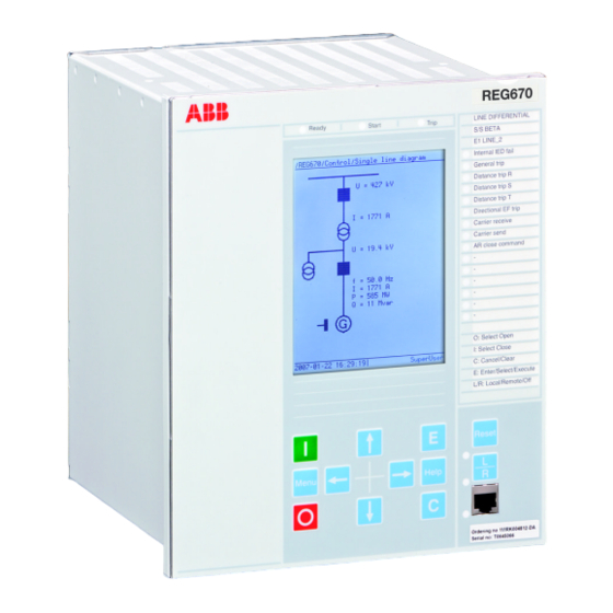
Section 3 1MRK 502 014-UEN C Overview Section 3 Overview About this chapter This chapter presents a general overview of the Operator's manual. Operator overview The Human machine interface (HMI) on the IED provides an ideal mechanism for the day to day operation and even advanced use of the IED. The keypad, LCD and LEDs on the front of the IED are what constitute the HMI. -
Page 23: Section 4 Understand The Local Human-Machine Interface
Section 4 1MRK 502 014-UEN C Understand the local human-machine interface Section 4 Understand the local human-machine interface About this chapter This chapter describes the display, its keys (buttons) and LEDs that make up the HMI. How the keys are used to navigate the HMI, how to interpret the graphic information on the LCD and, what the LEDs indicate is explained in the sections that follow. -
Page 24: Keypad
Section 4 1MRK 502 014-UEN C Understand the local human-machine interface IEC08000084 V1 EN Figure 2: 1/1 x 19” case with medium LCD Keypad The keypad is used to monitor and operate the IED. The keypad has the same look and feel in all IEDs. -
Page 25: Key Activated Screens
Section 4 1MRK 502 014-UEN C Understand the local human-machine interface Table 1: HMI keys on the front of the IED Function Press to close or energize a breaker or disconnector. IEC05000101 V1 EN Press to open a breaker or disconnector. IEC05000102 V1 EN Press to open two sub menus: Key operation and IED information. -
Page 26: The Reset Screen
Section 4 1MRK 502 014-UEN C Understand the local human-machine interface The I and O keys are used to open (OFF) and close (ON) breakers and disconnectors when using the Single Line Diagram (SLD) in direct control situations. 4.3.2 The Reset screen The reset screen is activated by the Reset key on the front panel of the IED or via the main menu. -
Page 27: Led
Section 4 1MRK 502 014-UEN C Understand the local human-machine interface 4.5.1 Introduction The LED module is a unidirectional means of communicating. This means that events may occur that activate a LED in order to draw the operators attention to something that has occurred and needs some sort of action. -
Page 28: Local Hmi Setup
Section 4 1MRK 502 014-UEN C Understand the local human-machine interface • Position error • CB spring charge alarm • Oil temperature alarm • Thermal overload trip • Bucholtz trip The RJ45 port has a yellow LED indicating that communication has been established between the IED and a computer. -
Page 29: Control
Section 4 1MRK 502 014-UEN C Understand the local human-machine interface Navigate to the desired parameter or quantity using the arrow keys. Press the E key when the parameter to be changed is highlighted. Move between digits or letters using the left and right arrow keys. Use the up and down arrow keys to change the digit or letter concerned. -
Page 31: Section 5 Understand The Hmi Tree
Section 5 1MRK 502 014-UEN C Understand the HMI tree Section 5 Understand the HMI tree About this chapter This chapter describes the structure of the HMI. The main menu includes submenus such as Measurements, Events, Disturbance Report, Settings, Diagnostics, Test and Reset. These branch out into a typical tree structure. Overview The local HMI has the following main menu: •... -
Page 33: Section 6 Read Measured Values
Section 6 1MRK 502 014-UEN C Read measured values Section 6 Read measured values About this chapter This chapter describes measurement categories and how to locate them using the HMI. Each measurement category has a section of its own that includes a general description of the type of quantity being measured and the path in the local HMI to the measurement. -
Page 34: View Analog Primary Values
Section 6 1MRK 502 014-UEN C Read measured values View analog primary values 6.2.1 Overview The analog primary values are analog quantities measured on the primary side of the TRM and reflect the actual current or voltage on the primary side of the VTs and CTs. -
Page 35: Ma Input Module Mim
Section 6 1MRK 502 014-UEN C Read measured values 6.4.1.1 mA input module MIM Main menu/Measurements/Analog mean values/mA modules/MIM Displays input data from the milli-ampere module which has six inputs. Each input has a range of +/- 20 mA. The value displayed on the screen is however dependant on the settings for the Milli-ampere Module. -
Page 36: Current Sequence Component Cmsqi
Section 6 1MRK 502 014-UEN C Read measured values Phase to earth voltages and phase angles are displayed here. 6.5.4 Current sequence component CMSQI Main menu/Measurements/Monitoring/CurrentSequenceComponents(MSQI)/ The current sequence component under monitoring displays the positive (I1), negative (I2) and zero sequence (I0) current values for a three phase line, both magnitude and phase angle for each component are displayed. -
Page 37: Section 7 Event List
Section 7 1MRK 502 014-UEN C Event list Section 7 Event list About this chapter This chapter describes how to find and read the event list. View events 7.1.1 Overview Events displays recorded events such as trips and breaker opened or closed. Main menu/Events Displays a list of events in chronological order and where each event has a time stamp. -
Page 39: Section 8 Handle Disturbances
Section 8 1MRK 502 014-UEN C Handle disturbances Section 8 Handle disturbances About this chapter This chapter describes disturbance detection and handling. This includes resetting LED alarms, triggering disturbance reports and the viewing of several fault indicators. Identify a disturbance A disturbance record can be generated manually by using the Manual Trig functionality in the HMI menu. -
Page 40: View Trip Values
Section 8 1MRK 502 014-UEN C Handle disturbances Main menu/Disturbance records/Record xx/Event recording 8.2.4 View trip values In the Trip values section of a disturbance recording both the pre-fault and the fault values for current, voltage and phase angle can be viewed. The recording number and Trig time are also displayed. -
Page 41: Section 9 Read And Change Settings
Section 9 1MRK 502 014-UEN C Read and change settings Section 9 Read and change settings About this chapter This chapter describes how to find and change settings and parameters. The chapter is divided into two sections which match the way the two categories of settings are divided up in the HMI. -
Page 42: Timesynchbin
Section 9 1MRK 502 014-UEN C Read and change settings Here the parameters FineSyncSource, CourseSyncSrc and SyncMaster are switched on or off. 9.1.2.3 TimeSynchBIN Main menu/Settings/Time/Synchronization/TimeSynchBIN Binary input synchronization settings available here are the position of the of the module, the number of the binary input and the detection mode. 9.1.2.4 TimeSynchDSTBegin Main menu/Settings/Time/Synchronization/TimeSynchDSTBegin... -
Page 43: Power System
Section 9 1MRK 502 014-UEN C Read and change settings Parameters under General settings that are changed will cause the IED to restart. This occurs automatically and requires no manual intervention. The IED must be in setting group 1 before changing settings in General settings 9.2.1 Power system... -
Page 44: Spa, Lon And Iec 60870-5-103 Settings
Section 9 1MRK 502 014-UEN C Read and change settings Each instance of CRB has several settable parameters where the channel mode can be set on or off, terminal numbers can be entered, synchronization can be set to master or slave and opto power can be set high or low. Each instance of CRM has several settable parameters. -
Page 45: Station Communication
Section 9 1MRK 502 014-UEN C Read and change settings Main menu/Settings/General settings/Communication/SLM configuration/ Rear optical SPA-IEC-DNP port In this submenu SPA or IEC is chosen and the necessary settings for the respective communication protocols are made. Main menu/Settings/General settings/Communication/SLM configuration/ Rear optical SPA-IEC port/Protocol selection SPA and IEC cannot run at the same time and in this submenu one of the options is chosen. -
Page 46: Ethernet Configuration
Section 9 1MRK 502 014-UEN C Read and change settings Includes available instances of Multicommand send settings allowing the user to adjust the maximum and minimum cycle time. Multicommand receive Main menu/Settings/General settings/Communication/Station communication/ MultiCommandReceive/CM Includes available instances of Multicommand receive settings allowing the user to adjust the maximum and minimum cycle time, the pulse duration and mode of operation. -
Page 47: Analog And I/O Modules
Section 9 1MRK 502 014-UEN C Read and change settings 9.2.3 Analog and I/O modules 9.2.3.1 Overview Under Analog modules in the General settings menu there are settings for Analog inputs and I/O modules. Within each instance of analog input there are settings for all 12 channels that include the name of the channel, star point of the CT circuit, the primary and secondary values from the measuring transformers (CTs and VTs). -
Page 48: Hmi
Section 9 1MRK 502 014-UEN C Read and change settings Settings for binary inputs and outputs (BIM, BOM, IOM), and under each binary module there are one or more adjustable parameters. In the I/O modules folder there is also a “reconfigure” setting that starts a dialog box prompting the user to confirm or cancel the command. -
Page 49: Differential Protection
Section 9 1MRK 502 014-UEN C Read and change settings The operation of the Change lock function can be activated or deactivated here. 9.2.5 Differential protection 9.2.5.1 Overview This group of settings covers differential protection of transformers. The system needs rated data to function properly. If the protection object is for example, a transformer, the rated current and voltage per winding as well as other relevant data will be needed. - Page 50 Section 9 1MRK 502 014-UEN C Read and change settings Reservation input, Circuit breakers and Circuit switches. The parameters include delay times, dependencies, pulse times and characteristics. Bay control QCBAY Main menu/Settings/General settings/Control/ApparatusControl/ BayControl(CBAY) Displays up to six instances of the bay control function QCBAY with a setting that gives the local operator priority over the remote operator or vice versa.
-
Page 51: Control Commands
Section 9 1MRK 502 014-UEN C Read and change settings Displays available instances of the Reservation input function RESIN with one settable parameter per function for future use. Switch controller SCSWI Main menu/Settings/General settings/Control/ApparatusControl/ SwitchController(CSWI)/CS Displays instances of the switch controller function SCSWI with eight settable parameters. -
Page 52: Service Values Cvmmxu
Section 9 1MRK 502 014-UEN C Read and change settings 9.2.7.2 Service values CVMMXU Main menu/Settings/General Settings/Monitoring/ServiceValues(MMXN)/SVR Displays available instances of CVMMXU. 9.2.7.3 Current phasors CMMXU Main menu/Settings/General Settings/Monitoring/CurrentPhasors(MMXU)/ Displays available instances of the current phasor function CMMXU with output regarding current amplitude, current range, phase angle, zero sequence current magnitude and negative sequence current magnitude. -
Page 53: Disturbance Report Drprdre
Section 9 1MRK 502 014-UEN C Read and change settings The voltage sequence components are where the user sets the limits and deadband settings for voltage sequence components. The designation for zero sequence voltage is 3U0, for positive sequence voltage is U1 and for negative sequence voltage is U2. -
Page 54: Logical Signal Status Report Binstatrep
Section 9 1MRK 502 014-UEN C Read and change settings 9.2.7.10 Logical signal status report BINSTATREP Main menu/Settings/General settings/Monitoring/BinarySignalStatusReport/ The Binary signal status report BINSTATREP settings consist of some sets of settable parameters with one settable parameter per instance. 9.2.7.11 IEC 60870–5–103 Main menu/Settings/General settings/Monitoring/IEC 60870–5–103 The IEC 60870–5–103 part of the settings menu is divided into two separate... -
Page 55: Setting Group N
Section 9 1MRK 502 014-UEN C Read and change settings Setting group N 9.3.1 Overview There are some default setting groups. Under general settings, parameters in these groups can be changed to suit the needs of an application. The default settings have been chosen according to established practice in the industry but will usually require a certain amount of adjustment to suit the requirements of individual applications. -
Page 56: Restricted Earth Fault Protection Refpdif
Section 9 1MRK 502 014-UEN C Read and change settings Displays available instances of T3WPDIF with a number of settings each. The settings for this function are identical to "Transformer differential protection, two winding T2WPDIF" 9.3.2.5 Restricted earth fault protection REFPDIF Main menu/Settings/Setting group N/Differential protection/ LowImpREF(PDIF,87N))/REF Displays available instances of REFPDIF with some settings per instance. -
Page 57: Pole Slip Protection Pspppam
Section 9 1MRK 502 014-UEN C Read and change settings 9.3.3.4 Pole slip protection PSPPPAM Main menu/Settings/Setting Group N/Impedance protection/PoleSlip(PPAM, 78)/PSP Measurement mode, impedance settings and other pole slip protection parameters are found here. 9.3.4 Current protection 9.3.4.1 Overview Under Current protection there are settings for Instantaneous phase overcurrent, Phase overcurrent four step, Instantaneous residual overcurrent, Residual overcurrent four step, Thermal overload with two time constants, Pole discordance and Breaker failure. -
Page 58: Instantaneous Residual Overcurrent Protection Efpioc
Section 9 1MRK 502 014-UEN C Read and change settings Displays some instances of PHPIOC with some settable parameters per instance. Operation mode, operate current multiplier, operation on or off, operate phase current level as a percentage of IBase, and IBase itself are the settable parameters available here. -
Page 59: Sensitive Directional Residual Over Current And Power Protection Sdepsde
Section 9 1MRK 502 014-UEN C Read and change settings 9.3.4.11 Sensitive directional residual over current and power protection SDEPSDE Main menu/Settings/Setting group N/Current protection/ SensDirResOvCurr(PSDE,67N)/SDE Includes voltage, current, operation mode and timer settings. 9.3.4.12 Thermal overload protection, two time constants TRPTTR Main menu/Settings/Setting Group N/Current protection/ ThermalOverload2TimeConst(PTTR,49)/TTR Displays some instances of TRPTTR with several settable parameters per instance. -
Page 60: Two Step Undervoltage Protection Uv2Ptuv
Section 9 1MRK 502 014-UEN C Read and change settings Displays up to several settable parameters for characteristics and many related parameters. 9.3.5.5 Two step undervoltage protection UV2PTUV Main menu/Settings/Setting Group N/Voltage protection/ UnderVoltage2Step(PTUV,27)/TUV Displays available settable parameters. The operation mode, the operate voltage as percentage of Ubase are examples of the settings available here. -
Page 61: Underfrequency Protection Saptuf
Section 9 1MRK 502 014-UEN C Read and change settings 9.3.6.4 Underfrequency protection SAPTUF Main menu/Settings/Setting Group N/Frequency protection/ Underfrequency(PTUF,81)/TUF Displays available instances of SAPTUF with a number of settings per instance. These include parameters like operation, base voltage, and start frequency. To ensure the proper operation of the Underfrequency function the Operation setting must be On. -
Page 62: Fuse Failure Supervision Sddrfuf
Section 9 1MRK 502 014-UEN C Read and change settings 9.3.8.3 Fuse failure supervision SDDRFUF Main menu/Settings/Setting Group N/Secondary system supervision/ FuseFailure(RFUF)/FSD Displays available instances of SDDRFUF with several settings per instance. There are parameters for operation, various thresholds and base values. 9.3.9 Control 9.3.9.1... -
Page 63: Tripping Logic Smpptrc
Section 9 1MRK 502 014-UEN C Read and change settings 9.3.11.2 Tripping logic SMPPTRC Main menu/Settings/Setting group N/Logic/TripLogic(PTRC,94)/TRP Displays available instances of the trip logic function SMPPTRCwith some settable parameters per instance. The settable parameters include operation, tripping order, trip lockout and minimum duration of trip output signal. 9.3.11.3 Trip matrix logic TMAGGIO Main menu/Settings/Setting group N/Logic/TripMatrix(GGIO)/TR... -
Page 65: Section 10 Diagnose Ied Status
Section 10 1MRK 502 014-UEN C Diagnose IED status Section 10 Diagnose IED status About this chapter This chapter describes where in the HMI tree to find the cause of an internal IED failure and information about the IED as such. 10.1 Read internal events Main menu/Diagnostics/Internal events... - Page 66 Section 10 1MRK 502 014-UEN C Diagnose IED status Displays various communication status signals for rear AB port communication. Main menu/ Diagnostics/Communication/Rear OEM - port CD Displays various communication status signals for rear CD port communication. Operator's manual...
-
Page 67: Section 11 Test The Ied
Section 11 1MRK 502 014-UEN C Test the IED Section 11 Test the IED About this chapter This chapter describes the tests that can be performed in the test section of the HMI. 11.1 Overview The test part of the tree view in the HMI has a number of submenus for test and viewing activities. -
Page 68: Ied Test Mode
Section 11 1MRK 502 014-UEN C Test the IED each with their own set of measurement data regarding interlocking, breaker and isolator conditions. 10. Logic displays a choice of functions available to the operator. These are Trip logic, Event counter, Logic gate, Logic memory and Logic timer set each with their own set of measurements. -
Page 69: Signal Matrix For Binary Input Smbi
Section 11 1MRK 502 014-UEN C Test the IED 11.3.1.2 Signal matrix for binary input SMBI Main menu/Test/Binary Input Values/SMT binary inputs/Instance:x Displays available instances of SMT binary inputs with several inputs per instance. 11.4 View binary output values 11.4.1 Overview Binary output values show the status of each individual output in the Binary output module (BOM). -
Page 70: Impedance Protection
Section 11 1MRK 502 014-UEN C Test the IED 11.5.3 Impedance protection Main menu/Test/Function test mode/Impedance protection Test of switch onto fault logic, distance protection zones one to five, local acceleration logic, power swing detection and phase selection with load encroachment. -
Page 71: Monitoring
Section 11 1MRK 502 014-UEN C Test the IED 11.5.10 Monitoring Main menu/Test/Function test modes/Monitoring Test of monitoring functions such as event counter and disturbance report. 11.5.11 Logic Main menu/Test/Function test modes/Logic Test of trip logic and event counter functions. 11.6 Function status 11.6.1... -
Page 72: Restricted Earth Fault Protection, Low Impedance Refpdif
Section 11 1MRK 502 014-UEN C Test the IED 11.6.1.4 Restricted earth fault protection, low impedance REFPDIF Main menu/Test/Function status/Differential protection/LowImpREF(PDIF, 87N)/REF Displays available instances of REFPDIF with several measurements per instance. The data available for this function includes Trip by the restricted earth fault protection function, start, operation of directional criteria due to internal fault, block due to second harmonic, start of switch onto fault, activation of second harmonic analysis, various fault detection indicators and the magnitude various... -
Page 73: Current Protection
Section 11 1MRK 502 014-UEN C Test the IED 11.6.3 Current protection Viewable data under Current protection consists mainly of trip status data under the various categories of current protection which include overcurrent protection, thermal overload, pole discordance and variations of these. 11.6.3.1 Breaker failure protection CCRBRF Main menu/Test/Function status/Current protection/BreakerFailure(RBRF,... -
Page 74: Four Step Phase Overcurrent Protection Oc4Ptoc
Section 11 1MRK 502 014-UEN C Test the IED Displays output data of NS4PTOC. 11.6.3.7 Four step phase overcurrent protection OC4PTOC Main menu/Test/Function status/Current protection/ PhaseOverCurrent4Step(PTOC,51_67)/TOC Displays available instances of OC4PTOC with several measurements per instance. These measurements are primarily trip and start signal indications from each phase and from the various steps in the protection scheme. -
Page 75: Voltage Protection
Section 11 1MRK 502 014-UEN C Test the IED 11.6.4 Voltage protection The viewable data available under voltage protection are mainly trip related and comprise data regarding undervoltage, overvoltage, residual overvoltage and overexcitation. 11.6.4.1 Overexcitation protection OEXPVPH Main menu/Test/Function status/Voltage protection/Overexcitation(PVPH,24)/ Displays available instances of OEXPVPH with a number of measurements per instance. -
Page 76: Voltage Differential Protection Vdcptov
Section 11 1MRK 502 014-UEN C Test the IED 11.6.4.6 Voltage differential protection VDCPTOV Main menu/Test/Function status/Voltage protection/VoltageDiff(PTOV,60)/ Displays the output data of VDCPTOV. 11.6.5 Frequency protection The measurements generated by the Underfrequency, Overfrequency and Rate-of- change of frequency functions are available under the paths outlined below. 11.6.5.1 Overfrequency protection SAPTOF Main menu/Test/Function status/Frequency protection/... -
Page 77: Secondary System Supervision
Section 11 1MRK 502 014-UEN C Test the IED Displays available instances of CVGAPC with a number of output quantities per instance. These include error signals from overcurrent functions, trip and start signals from overcurrent, undercurrent, overvoltage and undervoltage. There is a block signal caused by second harmonic detection. - Page 78 Section 11 1MRK 502 014-UEN C Test the IED The information shown here indicates whether or not switching of the earth switch is permitted and also indicates whether the earth switch QCis in the open or closed position. Interlock bus section breaker Main menu/Test/Function status/Control/Apparatus control/ InterlBusSectionBreaker/IH Displays the interlocking conditions that apply to the various switches and breakers.
- Page 79 Section 11 1MRK 502 014-UEN C Test the IED QA1 is permitted. (REL=release, ITL=interlock, OPTR=opened transmission, CLTR=closed transmission) Interlock, double circuit breaker bus A Main menu/Test/Function status/Control/Apparatus control/ InterlDoubleCBBusA/IB The outputs from this function show when closing of disconnectors and breakers is allowed and when it is not.
-
Page 80: Commands
Section 11 1MRK 502 014-UEN C Test the IED Bay reserve QCRSV Main menu/Test/Function status/Control/Apparatus control/ BayReserve(CRSV)/CR Displays available instances of the function QCRSV with several measurements per instance. Apart from the measurement for exchange signals between different BayRes blocks the output values are all boolean and indicate the status of processes and devices. -
Page 81: Iec61850 Generic Communication I/O Functions Dpggio
Section 11 1MRK 502 014-UEN C Test the IED Displays the output data of the VSGGIO function. 11.6.8.3 IEC61850 generic communication I/O functions DPGGIO Main menu/Test/Function status/Control/DoubelPointIndication(DPGGIO)/ Displays the output data of the DPGGIO function. 11.6.8.4 Synchrocheck and energizing check SESRSYN Main menu/Test/Function status/Control/Synchronizing(RSYN,25)/SYN Displays available instances of SESRSYN with a number of measurements per instance. -
Page 82: Generic Measured Value Mvggio
Section 11 1MRK 502 014-UEN C Test the IED Display the output data of the CNTGGIO function. 11.6.9.4 Generic measured value MVGGIO Main menu/Test/Function status/Monitoring/GenericMeasuredValue(GGIO)/ Displays the analog output from the MVGGIO block. The value shown here depends on the settings and the logical configuration of the preprocessing blocks. The measurement displayed may be current, voltage, frequency, phase angle etc. -
Page 83: Logic
Section 11 1MRK 502 014-UEN C Test the IED 11.6.10 Logic Under the Logic function folder there is viewable data for trip logic (showing number of poles that have tripped and trip signal information), event counter values, Logic gate outputs, Logic SR memory output states and Logic timer set output states are also shown here. -
Page 84: Logic Sr/Rs Memory
Section 11 1MRK 502 014-UEN C Test the IED 11.6.10.6 Logic SR/RS memory Main memory/Test/Function status/Logic/LogicSRMemory/SM Displays available instances of the function SM. The output data presented in the HMI is boolean and indicates whether or not a signal is present. For example, an output of one from SM01 OUT indicates that a signal exists on that output. -
Page 85: Setting Groups
Section 11 1MRK 502 014-UEN C Test the IED Main menu/Test/Function status/Communication/Station communication/ MultipleCommandReceive/CM The MultiCommand Receive indications displayed here show available sets of output data. Each set of output data has a number of signals. Other information displayed here shows whether there has been a change in data and whether data is valid. -
Page 86: Line Differential Test
Section 11 1MRK 502 014-UEN C Test the IED The Test LEDs menu enables the operator to activate LEDs manually. LEDs that do not light up are defective. Defective LEDs are also logged in Disturbance records under Monitoring. 11.8 Line differential test Main menu/Test/Line differential test/LineDiffLogic Settings used during test of line differential protection including test mode setting. -
Page 87: Section 12 Control And Supervise The Bay
Section 12 1MRK 502 014-UEN C Control and supervise the bay Section 12 Control and supervise the bay About this chapter This chapter describes the various control and supervision functions available in the HMI. In particular, how the single line diagram available on the display can be used for this purpose. - Page 88 Section 12 1MRK 502 014-UEN C Control and supervise the bay Main menu/Control/Single Line Diagram This is the path to the single line diagram from the main menu. The symbols used in the Single Line Diagram (SLD) are described in the table below Symbol Description Autotransformer...
-
Page 89: Control Screen Messages
Section 12 1MRK 502 014-UEN C Control and supervise the bay Symbol Description Surge arrestor xx05000243.vsd IEC05000243 V1 EN Trafo 2 windings xx05000244.vsd IEC05000244 V1 EN Trafo 3 windings xx05000245.vsd IEC05000245 V1 EN Truck xx05000248.vsd IEC05000248 V1 EN VT 2 windings xx05000247.vsd IEC05000247 V1 EN 12.1.3... -
Page 91: Section 13 Reset
Section 13 1MRK 502 014-UEN C Reset Section 13 Reset About this chapter This chapter describes how to reset the IED and when this is necessary. 13.1 Reset guide 13.1.1 Reset counters 13.1.1.1 Circuit breaker SXCBR The circuit breaker counter is reset under Reset counter in the HMI tree. Main menu/Reset/Reset counters/CircuitBreaker(XCBR)/XC In the dialog box that appears, choose YES to reset. -
Page 92: Function For Energy Calculation And Demand Handling Etpmmtr
Section 13 1MRK 502 014-UEN C Reset Activating Reset of LDCM counters sets the counter concerned to zero. A reset can be performed by affirmation in the dialog box. This is done by pressing the E key when YES is highlighted. 13.1.1.6 Function for energy calculation and demand handling ETPMMTR Main menuReset/Reset counters/ThreePhEnergMeas(MMTR)/ETP... -
Page 93: Reset Process Eventlist
Section 13 1MRK 502 014-UEN C Reset 13.1.5 Reset process eventlist Main menu/Reset/Reset process eventlist Local HMI setting for resetting the process eventlist. 13.1.6 Reset temperature functions Main menu/Reset/Reset temperature/ThermalOverload2TimeConstant(PTTR, 49)/THL In the dialog box that appears, choose YES to reset. Operator's manual... -
Page 95: Section 14 Authorization
Section 14 1MRK 502 014-UEN C Authorization Section 14 Authorization About this chapter This chapter describes password procedures and levels of access in the system. 14.1 Overview To safeguard the interests of our customers, both the IED and the tools that are accessing the IED are protected, subject of authorization handling. - Page 96 Section 14 1MRK 502 014-UEN C Authorization Table 2: Pre-defined user types Access rights System Protection Design User Guest Super User SPA Guest Operator Engineer Engineer Administrator Basic setting possibilities (change setting group, control settings, limit supervision) Advanced setting possibilities (for example protection settings) Basic control possibilities (process control, no bypass)
-
Page 97: Logon Or Logoff
Section 14 1MRK 502 014-UEN C Authorization At least one user must be included in the UserAdministrator group to be able to write users, created in PCM600, to IED. 14.3 LogOn or logOff The Authorization menu allows the user to logOn and, logOff. The HMI path is as follows: Main menu/Authorization 14.4... -
Page 99: Section 15 Glossary
1MRK 502 014-UEN C Glossary Section 15 Glossary About this chapter This chapter contains a glossary with terms, acronyms and abbreviations used in ABB technical documentation. Alternating current Application configuration tool within PCM600 A/D converter Analog to digital converter ADBS... - Page 100 Section 15 1MRK 502 014-UEN C Glossary CCITT Consultative Committee for International Telegraph and Telephony. A United Nations sponsored standards body within the International Telecommunications Union. CAN carrier module CCVT Capacitive Coupled Voltage Transformer Class C Protection Current Transformer class as per IEEE/ ANSI CMPPS Combined mega pulses per second CO cycle...
- Page 101 Section 15 1MRK 502 014-UEN C Glossary EHV network Extra high voltage network Electronic Industries Association Electro magnetic compatibility Electro motive force Electro magnetic interference EnFP End fault protection Electrostatic discharge FOX 20 Modular 20 channel telecommunication system for speech, data and protection signals FOX 512/515 Access multiplexer...
- Page 102 Section 15 1MRK 502 014-UEN C Glossary IEC 60870-5-103 Communication standard for protective equipment. A serial master/slave protocol for point-to-point communication IEC 61850 Substation Automation communication standard IEEE Institute of Electrical and Electronics Engineers IEEE 802.12 A network technology standard that provides 100 Mbits/s on twisted-pair or optical fiber cable IEEE P1386.1 PCI Mezzanine card (PMC) standard for local bus modules.
- Page 103 Section 15 1MRK 502 014-UEN C Glossary Light emitting diode LON network tool Local operating network Miniature circuit breaker Mezzanine carrier module Milli-ampere module Main processing module Multifunction vehicle bus. Standardized serial bus originally developed for use in trains. National Control Centre Numerical module OCO cycle Open-close-open cycle...
- Page 104 Section 15 1MRK 502 014-UEN C Glossary Relay characteristic angle REVAL Evaluation software RFPP Resistance for phase-to-phase faults RFPE Resistance for phase-to-earth faults RISC Reduced instruction set computer RMS value Root mean square value RS422 A balanced serial interface for the transmission of digital data in point-to-point connections RS485 Serial link according to EIA standard RS485...
- Page 105 Section 15 1MRK 502 014-UEN C Glossary TCP/IP Transmission control protocol over Internet Protocol. The de facto standard Ethernet protocols incorporated into 4.2BSD Unix. TCP/IP was developed by DARPA for internet working and encompasses both network layer and transport layer protocols. While TCP and IP specify two protocols at specific protocol layers, TCP/IP is often used to refer to the entire US Department of Defense protocol suite based upon these, including Telnet, FTP, UDP and RDP.
- Page 106 Section 15 1MRK 502 014-UEN C Glossary Three times the zero sequence voltage. Often referred to as the residual voltage or the neutral point voltage Operator's manual...
- Page 108 Contact us ABB AB Substation Automation Products SE-721 59 Västerås, Sweden Phone +46 (0) 21 32 50 00 +46 (0) 21 14 69 18 www.abb.com/substationautomation...