Siemens RUGGEDCOM RX1510 Installation Manual
Hide thumbs
Also See for RUGGEDCOM RX1510:
- Installation manual (62 pages) ,
- User manual (856 pages) ,
- Reference manual (148 pages)

Related Manuals for Siemens RUGGEDCOM RX1510


Summary of Contents for Siemens RUGGEDCOM RX1510
- Page 1 Preface Introduction Installing the Device RUGGEDCOM RX1510 Modules Technical Specifications Dimension Drawings Installation Guide Certification 09/2017 RC1055-EN-07...
-
Page 2: Security Information
Warranty Siemens warrants this product for a period of five (5) years from the date of purchase, conditional upon the return to factory for maintenance during the warranty term. This product contains no user-serviceable parts. Attempted service by unauthorized personnel shall render all warranties null and void. - Page 3 RUGGEDCOM RX1510 Installation Guide Industry Sector Tel: +1 905 856 5288 300 Applewood Crescent Fax: +1 905 856 1995 www.siemens.com/ruggedcom Concord, Ontario Canada, L4K 5C7...
- Page 4 RUGGEDCOM RX1510 Installation Guide...
-
Page 5: Table Of Contents
RUGGEDCOM RX1510 Installation Guide Table of Contents Table of Contents Preface ......................Alerts ..............................vii Related Documents ..........................viii Accessing Documentation ........................viii Training ............................viii Customer Support ..........................viii Chapter 1 Introduction ..................... 1.1 Feature Highlights ........................1 1.2 Description ........................... 2 Chapter 2 Installing the Device .................. - Page 6 RUGGEDCOM RX1510 Table of Contents Installation Guide Chapter 4 Technical Specifications .................. 4.1 Power Supply Specifications ......................31 4.2 Failsafe Relay Specifications ......................32 4.3 Operating Environment ....................... 32 4.4 Mechanical Specifications ......................32 Chapter 5 Dimension Drawings ..................Chapter 6 Certification ....................
-
Page 7: Preface
Installation Guide Preface Preface This guide describes the RUGGEDCOM RUGGEDCOM RX1510. It describes the major features of the device, installation, commissioning and important technical specifications. It is intended for use by network technical support personnel who are responsible for the installation, commissioning and maintenance of the device. -
Page 8: Related Documents
Siemens Sales representative. Customer Support Customer support is available 24 hours, 7 days a week for all Siemens customers. For technical support or general information, contact Siemens Customer Support through any of the following methods: Online Visit http://www.siemens.com/automation/support-request... - Page 9 RUGGEDCOM RX1510 Installation Guide Preface • Contact a local Siemens representative from Sales, Technical Support, Training, etc. • Ask questions or share knowledge with fellow Siemens customers and the support community Customer Support...
- Page 10 RUGGEDCOM RX1510 Preface Installation Guide Customer Support...
-
Page 11: Introduction
The RUGGEDCOM RX1510 is designed to provide a high level of immunity to electromagnetic interference (EMI) and heavy electrical surges typical of the harsh environments found in many industrial applications. An operating temperature range of -40 to 85 °C (-40 to 185 °F) allows the RUGGEDCOM RX1510 to be placed in almost any location. -
Page 12: Description
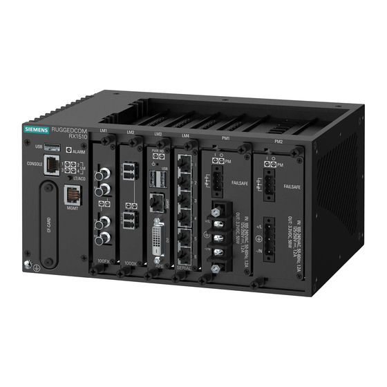
Installation Guide Section 1.2 Description The RUGGEDCOM RX1510 features various ports, controls and indicator LEDs on the front panel for connecting, configuring and troubleshooting the device. Figure 1: RUGGEDCOM RX1510 1. Utility USB Port 2. RS232 Serial Console Port (RJ45) 3. Lamp Test/Alarm Cut-Off (LT/ACO) Button 4. Compact Flash Card Port ... - Page 13 CAUTION! Configuration hazard – risk of data corruption/loss. Do not open the compact flash card port, unless specifically instructed to by a Siemens Customer Support representative. The warranty will be void otherwise. Removing the compact flash card improperly can corrupt configuration data.
- Page 14 Chapter 1 RUGGEDCOM RX1510 Introduction Installation Guide Description...
-
Page 15: Installing The Device
This product contains no user-serviceable parts. Attempted service by unauthorized personnel shall render all warranties null and void. Changes or modifications not expressly approved by Siemens Canada Ltd could invalidate specifications, test results, and agency approvals, and void the user's authority to operate the equipment. -
Page 16: General Procedure
Connect power to the device and ground the device to safety Earth. Connect the device to the network. Configure the device. Section 2.2 Required Tools and Materials The following tools and materials are required to install the RUGGEDCOM RX1510: Tools/Materials Purpose AC/DC power cord (16 AWG) For connecting power to the device. -
Page 17: Cabling Recommendations
Siemens also does not recommend using copper Ethernet ports to interface with devices in the field across distances that could produce high levels of ground potential rise (i.e. greater than 2500 V), during line-to-ground fault conditions. -
Page 18: Mounting The Device
Section 2.4 Mounting the Device The RUGGEDCOM RX1510 is designed for maximum mounting and display flexibility. It can be equipped with connectors that allow it to be installed in a 35 mm (1.4 in) DIN rail, or directly on a panel. -
Page 19: Mounting The Device To A Panel
Section 2.4.2 Mounting the Device to a Panel For panel installations, the RUGGEDCOM RX1510 can be equipped with panel/DIN rail adapters pre-installed on each side of the chassis. The adapters allow the device to be attached to a panel using screws. -
Page 20: Connecting Power
1. Normally Open 2. Common 3. Normally Closed Section 2.6 Connecting Power The RUGGEDCOM RX1510 supports dual redundant high AC, high DC and/or low DC power modules that can be installed in any combination. The use of two power modules is recommended to provide redundancy and load balancing. -
Page 21: Connecting High Ac/Dc Power
RUGGEDCOM RX1510 Chapter 2 Installation Guide Installing the Device • Equipment must be installed according to applicable local wiring codes and standards. CONTENTS • Section 2.6.1, “Connecting High AC/DC Power” • Section 2.6.2, “Connecting Low DC Power” Section 2.6.1 Connecting High AC/DC Power... - Page 22 Chapter 2 RUGGEDCOM RX1510 Installing the Device Installation Guide Figure 6: AC Terminal Block Wiring – Screw-Type Terminal Block for HI Power Supplies 1. 5-Position Terminal Block 2. 3-Position Terminal Block 3. Positive/Live (+/L) Terminal 4. Ground Terminal 5. Negative/Neutral (-/N) Terminal Connect the positive wire from the power source to the positive/live (+/L) terminal on the terminal block.
-
Page 23: Connecting Low Dc Power
RUGGEDCOM RX1510 Chapter 2 Installation Guide Installing the Device Section 2.6.2 Connecting Low DC Power To connect a low DC power supply to the device, do the following: CAUTION! Electrical hazard – risk of damage to equipment. Do not connect AC power cables to a 12, 24 or 48 VDC power supply terminal block. - Page 24 Chapter 2 RUGGEDCOM RX1510 Installing the Device Installation Guide Figure 9: DC Terminal Block Wiring – Screw-Type Terminal Block for 12, 24 and 48 Power Supplies 1. 5-Position Terminal Block 2. 3-Position Terminal Block 3. Positive (+) Terminal 4. Negative (-) Terminal 5. Ground Terminal Connect the positive wire from the power source to the positive (+) terminal on the terminal block.
-
Page 25: Connecting To The Device
For information about how to connect to the device via the management port, refer to either the RUGGEDCOM ROX II Web Interface User Guide or the RUGGEDCOM ROX II CLI User Guide for the RUGGEDCOM RX1510. The management port is a 10/100Base-TX copper Ethernet port with an RJ-45 connector. The following is the pin-... -
Page 26: Communication Ports
Chapter 2 RUGGEDCOM RX1510 Installing the Device Installation Guide Name Description Receive Data+ Receive Data- Transmit Data+ Reserved (Do Not Connect) Figure 12: RJ-45 Management Port Reserved (Do Not Connect) Transmit Data- Reserved (Do Not Connect) Reserved (Do Not Connect) Communication Ports Connect any of the available Ethernet ports on the device to a management switch and access the RUGGEDCOM ROX II console and Web interfaces via the device's IP address. -
Page 27: Modules
Modules Modules The RUGGEDCOM RX1510 features slots for up to two field-replaceable line modules, which can be used to expand and customize the capabilities of the device to suit specific applications. A variety of modules are available, each featuring a specific type of communication port: copper Ethernet, fiber optic Ethernet, SFP, WAN, cellular modem and DDS. -
Page 28: Available Modules
Modules Installation Guide Section 3.1 Available Modules The following is a list of all power and line modules available for use in the RUGGEDCOM RX1510. For more RUGGEDCOM RX1500 Series Modules Catalog information about individual modules, refer to the [https:// support.industry.siemens.com/cs/ca/en/view/109747072]. - Page 29 RUGGEDCOM RX1510 Chapter 3 Installation Guide Modules RUGGEDCOM RX1500PN PS 48 Specifications Article Numbers Input Range: 36 to 72 VDC 6GK6015-0AL12-0AA0 (Standard) Terminal Type: Screw 6GK6015-0AL12-0AA1 (Conformal Coated) RUGGEDCOM RX1500PN PS 48P Specifications Article Numbers Input Range: 36 to 72 VDC...
- Page 30 Chapter 3 RUGGEDCOM RX1510 Modules Installation Guide RUGGEDCOM RX1500PN LM CG03B Specifications Article Numbers Ports: 2 6GK6015-0AL20-0PE0 (Standard) Speed: 1000 Mbps 6GK6015-0AL20-0PE1 (Conformal Coated) Interface: TX Port Type: M12 (8-Pin, A-Coded, Controlled Bypass) Distance: 100 m (328 ft) RUGGEDCOM RX1500PN LM X CG04...
- Page 31 RUGGEDCOM RX1510 Chapter 3 Installation Guide Modules RUGGEDCOM RX1500PN LM 6TX01 Specifications Article Numbers Ports: 6 6GK6015-0AL20-0NB0 (Standard) Speed: 100 Mbps 6GK6015-0AL20-0NB1 Interface: TX (Conformal Coated) Port Type: RJ45 Distance: 100 m (328 ft) Fiber Optic Ethernet Modules RUGGEDCOM RX1500PN LM 4FX11...
-
Page 32: Wan Modules
Chapter 3 RUGGEDCOM RX1510 Modules Installation Guide RUGGEDCOM RX1500PN LM 6FX50 Specifications Article Numbers SFP Sockets: 6 6GK6015-0AL20-0JD0 (Standard) Speed: 100 Mbps 6GK6015-0AL20-0JD1 (Conformal Coated) WAN Modules RUGGEDCOM RX1500PN LM S01 Specifications Article Numbers (Standard) Standard: RS232/RS422/RS485 6GK6015-0AL20-0KB0 (Standard) Ports: 6... - Page 33 RUGGEDCOM RX1510 Chapter 3 Installation Guide Modules SIM: Dual Mini-SIM (2FF) RUGGEDCOM RX1500PN LM W12 Specifications Article Numbers (Standard) Services: GSM/EDGE/HSPA+ 6GK6015-0AL20-0WC0 (Standard) Region: North America (AT&T), European Union, Australia 6GK6015-0AL20-0WC1 (Conformal Coated) Port Type: 50 Ω SMA Antennas: 2 x GSM/EDGE/HSPA+,...
- Page 34 Chapter 3 RUGGEDCOM RX1510 Modules Installation Guide SIM: Dual Mini-SIM (2FF) RUGGEDCOM RX1500PN LM W61 Specifications Article Numbers (Standard) Services: 4G LTE/HSPA+/CDMA/ 6GK6015-0AL20-0WJ0 EVDO/GPS/GNSS (Standard) Region: North America (Verizon, 6GK6015-0AL20-0WJ1 Sprint) (Conformal Coated) Port Type: 50 Ω SMA Antennas: 1 x LTE Main, 1 x LTE...
- Page 35 RUGGEDCOM RX1510 Chapter 3 Installation Guide Modules RUGGEDCOM RX1500PN LM APE1404 Specifications Article Numbers (Standard) Operating System: Debian Linux® 6GK6015-0AL20-0GD0 (Standard) Processor: Intel Atom E660T 1.3 GHz, 512 KB L2 Cache 6GK6015-0AL20-0GD1 (Conformal Coated) RAM: 2 GB DDR2, 800 MHz, 32-...
-
Page 36: Installing/Removing Line Modules
Chapter 3 RUGGEDCOM RX1510 Modules Installation Guide RUGGEDCOM RX1500PN LM Blank Specifications Article Numbers — 6GK6015-0AL20-0AA0 (Standard) 6GK6015-0AL20-0AA1 (Conformal Coated) Section 3.2 Installing/Removing Line Modules Upon installing a new line module in the device, all features associated with the module are available in RUGGEDCOM ROX II. -
Page 37: Installing A Module
RUGGEDCOM RX1510 Chapter 3 Installation Guide Modules Figure 14: Removing a Module 1. Module 2. Chassis 3. Screw Install a new module or a blank module (to prevent the ingress of dust and dirt). [Optional] If necessary, install the device in the rack. Connect power to the device. -
Page 38: Installing/Removing Power Modules
Tighten the screws to secure the module. [Optional] If necessary, install the device in the rack. Connect power to the device. Section 3.3 Installing/Removing Power Modules The RUGGEDCOM RX1510 supports dual redundant power supply modules. Figure 16: Power Modules 1. Slot PS1 2. Slot PS2 Installing/Removing Power Modules... -
Page 39: Removing A Power Module
RUGGEDCOM RX1510 Chapter 3 Installation Guide Modules CAUTION! Contamination hazard – risk of equipment damage. Prevent the ingress of water, dirts and other debris that may lead to premature equipment failure. Always make sure slots are not left empty. NOTE Power modules are hot swappable. - Page 40 Chapter 3 RUGGEDCOM RX1510 Modules Installation Guide If applicable, connect the supplied terminal block to the module or connect the terminal block from the previous module. Confirm or connect the wiring from the power supply to the module. For more information, refer to Section 2.6, “Connecting...
-
Page 41: Technical Specifications
RUGGEDCOM RX1510 Chapter 4 Installation Guide Technical Specifications Technical Specifications This section provides important technical specifications related to the device. CONTENTS • Section 4.1, “Power Supply Specifications” • Section 4.2, “Failsafe Relay Specifications” • Section 4.3, “Operating Environment” • Section 4.4, “Mechanical Specifications” Section 4.1... -
Page 42: Failsafe Relay Specifications
Temperature limits for select line modules may differ from that which can be withstood by the RUGGEDCOM RX1510. Make sure the selected modules are rated for the expected environmental conditions before deployment. For more information, refer to the RUGGEDCOM RX1510 Series Modules Catalog. -
Page 43: Dimension Drawings
RUGGEDCOM RX1510 Chapter 5 Installation Guide Dimension Drawings Dimension Drawings NOTE All dimensions are in millimeters, unless otherwise stated. - Page 44 Chapter 5 RUGGEDCOM RX1510 Dimension Drawings Installation Guide 237.74 Figure 19: Overall Dimensions...
- Page 45 RUGGEDCOM RX1510 Chapter 5 Installation Guide Dimension Drawings 286.5 152.4 276.4 78.2 Figure 20: Panel and Din Rail Mount Dimensions 162.5 151.4 19.7 Figure 21: Line Module Dimensions...
- Page 46 Chapter 5 RUGGEDCOM RX1510 Dimension Drawings Installation Guide 162.5 151.8 40.6 Figure 22: Power Module Dimensions...
-
Page 47: Certification
Installation Guide Certification Certification The RUGGEDCOM RX1510 device has been thoroughly tested to guarantee its conformance with recognized standards and has received approval from recognized regulatory agencies. NOTE Certifications related to individual modules are detailed in the RUGGEDCOM Modules Catalog for the device available online. -
Page 48: European Union (Eu)
The device is marked with a CE marking and notified body number, and can be used throughout the European community. 0680 A copy of the CE Declaration of Conformity is available from Siemens Canada Ltd. For contact information, refer to “Contacting Siemens”. -
Page 49: Fcc
• Title 21 Code of Federal Regulations (CFR) – Chapter I – Sub-chapter J – Radiological Health Section 6.1.5 ISED This device is declared by Siemens Canada Ltd to meet the requirements of the following ISED (Innovation Science and Economic Development Canada) standard: • CAN ICES-3 (A)/NMB-3 (A) Section 6.1.6... -
Page 50: Other Approvals
• IEC 61850-3 Communication Networks and Systems in Substations – Part 3: General Requirements Section 6.2 EMC and Environmental Type Tests The RUGGEDCOM RX1510 has passed the following Electromagnetic Compatibility (EMC) and environmental tests. EMC Type Test for IEC 61850-3 Severity Test... - Page 51 EMC Immunity Type Tests for IEEE 1613 NOTE The RUGGEDCOM RX1510 meets Class 2 requirements for an all-fiber configuration and Class 1 requirements for copper ports. Class 1 allows for temporary communication loss, while Class 2 requires error-free and interrupted communications.
-
Page 52: Environmental Type Tests
Chapter 6 RUGGEDCOM RX1510 Certification Installation Guide Description Test Levels Earth ground ports Oscillatory Signal ports 2.5 kV common mode @1MHz DC Power Ports 2.5 kV common 1 kV differential mode @ 1 MHz AC Power Ports Radiated RFI Enclosure ports...