Siemens RUGGEDCOM RX1501 Installation Manual
Simatic net rugged multi service platforms
Hide thumbs
Also See for RUGGEDCOM RX1501:
- Installation manual (68 pages) ,
- User manual (856 pages) ,
- Reference manual (148 pages)

Related Manuals for Siemens RUGGEDCOM RX1501


Summary of Contents for Siemens RUGGEDCOM RX1501
- Page 1 Edition 04/2022 Installation Manual SIMATIC NET Rugged Multi Service Platforms RUGGEDCOM RX1501 https://www.siemens.com/ruggedcom...
- Page 2 Preface Introduction Installing the Device SIMATIC NET Device Management Rugged Multi Service Platforms RUGGEDCOM RX1501 Modules Technical Specifications Installation Manual Certification 04/2022 C79000-G8976-1054-22...
- Page 3 Note the following: WARNING Siemens products may only be used for the applications described in the catalog and in the relevant technical documentation. If products and components from other manufacturers are used, these must be recommended or approved by Siemens. Proper transport, storage, installation, assembly, commissioning, operation and maintenance are required to ensure that the products operate safely and without any problems.
-
Page 4: Table Of Contents
Accessing Documentation ....................... v Registered Trademarks ......................v Warranty ..........................vi Training ..........................vi Customer Support ........................vii Contacting Siemens ....................... vii Introduction ........................... 1 Feature Highlights ....................1 Description ......................1 Required Tools and Materials ................. 3 Decommissioning and Disposal ................3 Cabling Recommendations .................. - Page 5 FDA/CDRH ......................43 6.1.6 ISED ........................43 6.1.7 ISO ........................44 6.1.8 ANATEL ....................... 44 6.1.9 ACMA ........................44 6.1.10 RoHS ........................45 6.1.11 Other Approvals ....................45 EMC and Environmental Type Tests ..............45 RUGGEDCOM RX1501 Installation Manual, 04/2022, C79000-G8976-1054-22...
-
Page 6: Preface
Preface This guide describes the RUGGEDCOM RX1501. It describes the major features of the device, installation, commissioning and important technical specifications. It is intended for use by network technical support personnel who are responsible for the installation, commissioning and maintenance of the device. It is also recommended for use by network and system planners, system programmers, and line technicians. -
Page 7: Warranty
Warranty Siemens warrants this product for a period of five (5) years from the date of purchase, conditional upon the return to factory for maintenance during the warranty term. This product contains no user-serviceable parts. Attempted service by unauthorized personnel shall render all warranties null and void. -
Page 8: Customer Support
Preface Customer Support Customer Support Customer support is available 24 hours, 7 days a week for all Siemens customers. For technical support or general information, contact Siemens Customer Support through any of the following methods: Online Visit http://www.siemens.com/automation/support-request to submit a Support Request (SR) or check on the status of an existing SR. - Page 9 Preface Contacting Siemens viii RUGGEDCOM RX1501 Installation Manual, 04/2022, C79000-G8976-1054-22...
-
Page 10: Introduction
(EMI) and heavy electrical surges typical of the harsh environments found in many industrial applications. An operating temperature range of -40 to 85 °C (-40 to 185 °F) allows the RUGGEDCOM RX1501 to be placed in almost any location. - Page 11 "Connecting to the Device (Page 21)". Utility USB Port Use the USB port to upgrade the RUGGEDCOM RX1501 software or install files, such as configuration files and feature key files. For more information, refer to the "RUGGEDCOM ROX Configuration Manual" for the RUGGEDCOM RX1501.
-
Page 12: Required Tools And Materials
Introduction 1.3 Required Tools and Materials Required Tools and Materials The following tools and materials are required to install the RUGGEDCOM RX1501: Tools/Materials Purpose AC/DC power cord (16 AWG) For connecting power to the device. Lightning protector For protecting the device from harmful electrical strikes. -
Page 13: Protection On Twisted-Pair Data Ports
Siemens also does not recommend using copper Ethernet ports to interface with devices in the field across distances that could produce high levels of ground potential rise (i.e. greater than 2500 V), during line-to-ground fault conditions. -
Page 14: Installing The Device
The surface of the device may be hot during operation, or as a result of the ambient air temperature. Wear appropriate personal protective equipment and use caution when working with or around the device. RUGGEDCOM RX1501 Installation Manual, 04/2022, C79000-G8976-1054-22... -
Page 15: General Procedure
This product contains no user-serviceable parts. Attempted service by unauthorized personnel shall render all warranties null and void. Changes or modifications not expressly approved by Siemens Canada Ltd. could invalidate specifications, test results, and agency approvals, and void the user's authority to operate the equipment. -
Page 16: Mounting The Device
"Dimension Drawings (Page 36)". 2.3.1 Mounting the Device to a Rack For rack mount installations, the RUGGEDCOM RX1501 can be equipped with rack mount adapters pre-installed at the front or rear of the chassis. Additional adapters are provided for added stability. NOTICE Vibration hazard –... -
Page 17: Mounting The Device On A Din Rail
2.3.2 Mounting the Device on a DIN Rail For DIN rail installations, the RUGGEDCOM RX1501 can be equipped with panel/DIN rail adapters pre-installed on each side of the chassis. The adapters allow the device to be slid onto a standard 35 mm (1.4 in) DIN rail. -
Page 18: Mounting The Device To A Panel
2.3.3 Mounting the Device to a Panel For panel installations, the RUGGEDCOM RX1501 can be equipped with panel/DIN rail adapters pre-installed on each side of the chassis. The adapters allow the device to be attached to a panel using screws. -
Page 19: Connecting The Failsafe Alarm Relay
NO contact and closes the NC (Normally Closed) contact. Note Control of the failsafe relay output is configurable through RUGGEDCOM RX1501. One common application for this relay is to signal an alarm if a power failure occurs. For more information, refer to the "RUGGEDCOM ROX Configuration Manual" for the RUGGEDCOM RX1501. -
Page 20: Connecting Power
Figure 2.4 Failsafe Alarm Relay Wiring Connecting Power The RUGGEDCOM RX1501 supports a single high AC, high DC or low DC power module. Power modules can be equipped with either a screw or European-style (Euroblock) terminal block. The screw terminal block is installed using Phillips screws and compression plates, allowing either bare wire connections or crimped terminal lugs. -
Page 21: Connecting High Ac/Dc Power
NOTICE Electrical hazard – risk of damage to equipment Do not connect AC power cables to a 12, 24 or 48 VDC power supply terminal block. Damage to the power supply may occur. RUGGEDCOM RX1501 Installation Manual, 04/2022, C79000-G8976-1054-22... - Page 22 Ground Terminal Negative/Neutral (-/N) Terminal Figure 2.5 AC Terminal Block Wiring – European-style (Euroblock) Terminal Block for HIP Power Supplies Not Connected Removable Screw Terminal Block Non-removable Screw Terminal Block Positive/Live (+/L) Terminal Ground Terminal RUGGEDCOM RX1501 Installation Manual, 04/2022, C79000-G8976-1054-22...
- Page 23 For screw terminal blocks, install the safety cover. Screw Safety Cover Screw Terminal Block RUGGEDCOM RX1501 Device Figure 2.7 Assembling the Safety Cover Using a braided wire or other appropriate grounding wire, connect the ground terminal to the chassis ground connection.
-
Page 24: Connecting Low Dc Power
Do not connect AC power cables to a 12, 24 or 48 VDC power supply terminal block. Damage to the power supply may occur. Note The RUGGEDCOM RX1501 works with both positive VDC power supplies and negative VDC power supplies. RUGGEDCOM RX1501... - Page 25 Ground Terminal Figure 2.9 DC Terminal Block Wiring – European-style (Euroblock) Terminal Block for 12P, 24P and 48P Power Supplies Not Connected Removable Screw Terminal Block Non-removable Screw Terminal Block Positive (+) Terminal Negative (-) Terminal RUGGEDCOM RX1501 Installation Manual, 04/2022, C79000-G8976-1054-22...
- Page 26 Ground Terminal Figure 2.11 DC Terminal Block Wiring – European-style (Euroblock) Terminal Block for -12P, -24P and -48P Power Supplies Not Connected Removable Screw Terminal Block Non-removable Screw Terminal Block Positive (+) Terminal Negative (-) Terminal RUGGEDCOM RX1501 Installation Manual, 04/2022, C79000-G8976-1054-22...
- Page 27 Connect the negative wire from the power source to the negative (-) terminal on the terminal block. For screw terminal blocks, install the safety cover. Screw Safety Cover Screw Terminal Block RUGGEDCOM RX1501 Device Figure 2.13 Assembling the Safety Cover RUGGEDCOM RX1501 Installation Manual, 04/2022, C79000-G8976-1054-22...
- Page 28 #10 Ring Lug #10-32 Screw Connection from External Power Source Ground Connection Figure 2.14 Ground Connection Install the safety cover over the terminal block. This is mandatory for 48 VDC and -48 VDC power supplies. RUGGEDCOM RX1501 Installation Manual, 04/2022, C79000-G8976-1054-22...
- Page 29 Installing the Device 2.5.2 Connecting Low DC Power RUGGEDCOM RX1501 Installation Manual, 04/2022, C79000-G8976-1054-22...
-
Page 30: Device Management
This section describes how to connect to and manage the device. Connecting to the Device The following describes the various methods for accessing the RUGGEDCOM RX1501 console and Web interfaces on the device. For more detailed instructions, refer to the "RUGGEDCOM ROX Configuration Manual"... - Page 31 Connect any of the available Ethernet ports on the device to a management switch and access the RUGGEDCOM RX1501 console and Web interfaces via the device's IP address. The factory default IP address for the RUGGEDCOM RX1501 is https://192.168.0.2. For more information about available ports, refer to "Modules (Page...
-
Page 32: Configuring The Device
The following will void the warranty and potentially result in configuration data corruption/loss: • Using a CF card not approved by Siemens for use with this device • Removing the CF card in any scenario other than those described in this section... - Page 33 Inserting the CF Card Secure the CF card access panel to the chassis. Removing the CF card To remove the CF card from the device, do the following: Make sure the device is powered down. RUGGEDCOM RX1501 Installation Manual, 04/2022, C79000-G8976-1054-22...
- Page 34 CompactFlash Card Access Panel Figure 3.4 Removing the CF Card Press the ejector button to the left of the CF card and then pull the card out. Secure the CF card access panel to the chassis. RUGGEDCOM RX1501 Installation Manual, 04/2022, C79000-G8976-1054-22...
- Page 35 Device Management 3.3 Accessing the CompactFlash Card RUGGEDCOM RX1501 Installation Manual, 04/2022, C79000-G8976-1054-22...
-
Page 36: Modules
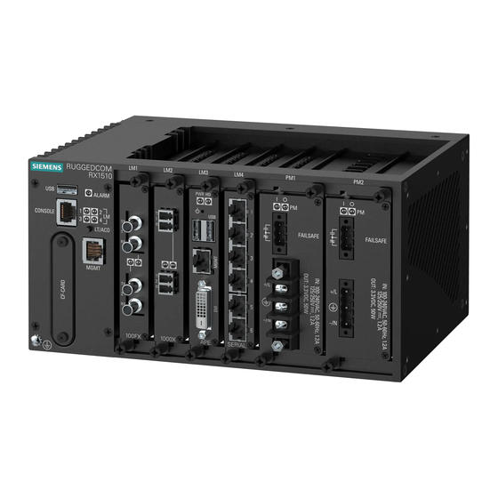
Modules The RUGGEDCOM RX1501 features slots for up to six field-replaceable line modules, which can be used to expand and customize the capabilities of the device to suit specific applications. A variety of modules are available, each featuring a specific type of communication port: copper Ethernet, fiber optic Ethernet, SFP, WAN, cellular modem and DDS. -
Page 37: Available Modules
2-Port Fiber Optic (FG50 + SFPs) 14 W 6-Port Copper (M12, RJ45) Total Consumption 43 W Available Modules A variety of modules are available for use with the RUGGEDCOM RX1501. For more information, refer to the "RUGGEDCOM Modules Catalog [https:// support.industry.siemens.com/cs/us/en/view/109747072]" for the RUGGEDCOM RX1501. -
Page 38: Installing/Removing Line Modules
Installing/Removing Line Modules Upon installing a new line module in the device, all features associated with the module are available in RUGGEDCOM RX1501. For more information, refer to the "RUGGEDCOM ROX Configuration Manual" for the RUGGEDCOM RX1501. Once a line module is removed, all the features associated with the module are hidden or disabled in RUGGEDCOM RX1501. - Page 39 Remove the current module from the slot. Insert the new module into the slot. Module Chassis Screw Figure 4.3 Installing a Module Tighten the screws to secure the module. [Optional] If necessary, install the device in the rack. RUGGEDCOM RX1501 Installation Manual, 04/2022, C79000-G8976-1054-22...
-
Page 40: Installing/Removing Power Modules
Modules 4.4 Installing/Removing Power Modules Installing/Removing Power Modules The RUGGEDCOM RX1501 supports a single power module. Power Module Figure 4.4 Power Module NOTICE Contamination hazard – risk of equipment damage Prevent the ingress of water, dirts and other debris that may lead to premature equipment failure. - Page 41 If applicable, connect the supplied terminal block to the module or connect the terminal block from the previous module. Confirm or connect the wiring from the power supply to the module. For more information, refer to "Connecting Power (Page 11)". RUGGEDCOM RX1501 Installation Manual, 04/2022, C79000-G8976-1054-22...
- Page 42 Turn on power to the device and confirm the module is receiving and supplying power. This is indicated by the LEDs on the module. State Description Green The module is supplying power Green The module is receiving power RUGGEDCOM RX1501 Installation Manual, 04/2022, C79000-G8976-1054-22...
- Page 43 Modules 4.4 Installing/Removing Power Modules RUGGEDCOM RX1501 Installation Manual, 04/2022, C79000-G8976-1054-22...
-
Page 44: Technical Specifications
Power consumption varies based on the device configuration. (T) denotes time-delay fuse. Failsafe Relay Specifications Maximum Switching Voltage Rated Switching Current Isolation 30 VDC 2800 VDC for 1 minute between coil and contacts 125 VDC 0.1 A , 0.15 A RUGGEDCOM RX1501 Installation Manual, 04/2022, C79000-G8976-1054-22... -
Page 45: Operating Environment
6.25 A Inductive load R/L = 7 ms Resistive load Operating Environment The RUGGEDCOM RX1501 is rated to operate under the following environmental conditions. Note Temperature limits for select line modules may differ from that which can be withstood by the RUGGEDCOM RX1501. Make sure the selected modules are rated for the expected environmental conditions before deployment. - Page 46 Technical Specifications 5.6 Dimension Drawings 440.9 Figure 5.1 Overall Dimensions RUGGEDCOM RX1501 Installation Manual, 04/2022, C79000-G8976-1054-22...
- Page 47 Technical Specifications 5.6 Dimension Drawings 11.7 463.8 21.1 Figure 5.2 Rack Mount Dimensions 479.0 21.1 11.7 489.2 Figure 5.3 Panel and Din Rail Mount Dimensions RUGGEDCOM RX1501 Installation Manual, 04/2022, C79000-G8976-1054-22...
- Page 48 Technical Specifications 5.6 Dimension Drawings 162.5 151.4 19.7 Figure 5.4 Line Module Dimensions 162.5 151.8 40.6 Figure 5.5 Power Module Dimensions RUGGEDCOM RX1501 Installation Manual, 04/2022, C79000-G8976-1054-22...
- Page 49 Technical Specifications 5.6 Dimension Drawings RUGGEDCOM RX1501 Installation Manual, 04/2022, C79000-G8976-1054-22...
-
Page 50: Certification
Certification The RUGGEDCOM RX1501 device has been thoroughly tested to guarantee its conformance with recognized standards and has received approval from recognized regulatory agencies. Note Certifications related to individual modules are detailed in the "RUGGEDCOM Modules Catalog" for the device available online. -
Page 51: European Union (Eu)
Certification 6.1.3 European Union (EU) 6.1.3 European Union (EU) This device is declared by Siemens Canada Ltd. to comply with essential requirements and other relevant provisions of the following EU directives: • Directive 2014/30/EU Directive 2014/30/EU of the European Parliament and of the Council of 26... -
Page 52: Fcc
The device is marked with a CE marking and notified body number, and can be used throughout the European community. 0680 A copy of the CE Declaration of Conformity is available from Siemens Canada Ltd.. For contact information, refer to "Contacting Siemens (Page vii)". -
Page 53: Iso
Anexo à Resolução Anatel nº 442/2006 Notices specific to ANATEL: Note The RUGGEDCOM RX1501 is not certified for use on 2G, 3G or 4G LTE networks in Brazil. Note This equipment operates on a secondary basis. That is, it is not entitled to protection against harmful interference, even from the same type of station, and may not cause interference to systems operating on a primary basis. -
Page 54: Rohs
Support at https://support.industry.siemens.com/cs/ww/en/view/89855782. 6.1.10 RoHS This device is declared by Siemens Canada Ltd. to meet the requirements of the following RoHS (Restriction of Hazardous Substances) directives for the restricted use of certain hazardous substances in electrical and electronic equipment: China RoHS 2 •... - Page 55 2 kV (Failsafe Relay output) DC Power Ports 1.5 kV AC Power Ports 2 kV HV Impulse Signal ports 5 kV (Failsafe Relay output) DC Power Ports 5 kV AC Power Ports Siemens-specified severity levels. RUGGEDCOM RX1501 Installation Manual, 04/2022, C79000-G8976-1054-22...
- Page 56 30 g @ 11 ms Class 2 Bump 10 g @ 16 ms Class 1 IEC 61373 Long Life (Random Vibration) Category 1 Class B Shock IEC 60255-21-3 Seismic Method A Level 2 RUGGEDCOM RX1501 Installation Manual, 04/2022, C79000-G8976-1054-22...
- Page 57 Certification 6.2 EMC and Environmental Type Tests Military Standard Tests Test Description Test Levels MIL-STD-810G Altitude 12192 m (40000 ft) @ 40 °C, 90 minutes RUGGEDCOM RX1501 Installation Manual, 04/2022, C79000-G8976-1054-22...
- Page 58 For more information Siemens RUGGEDCOM https://www.siemens.com/ruggedcom Industry Online Support (service and support) https://support.industry.siemens.com Industry Mall https://mall.industry.siemens.com Siemens Canada Ltd. Digital Industries Process Automation 300 Applewood Crescent Concord, Ontario, L4K 4E5 Canada © 2022 Siemens Canada Ltd. Subject to change...