ABB RET650 Applications Manual
Relion 650 series, transformer protection
Hide thumbs
Also See for RET650:
- Technical manual (670 pages) ,
- Commissioning manual (112 pages) ,
- Product manual (70 pages)

Related Manuals for ABB RET650


Summary of Contents for ABB RET650
- Page 1 — R E L I O N ® 650 SERIES Transformer protection RET650 Version 2.2 Application manual...
- Page 3 Document ID: 1MRK 504 169-UEN Issued: October 2017 Revision: A Product version: 2.2.1 © Copyright 2017 ABB. All rights reserved...
- Page 4 Copyright This document and parts thereof must not be reproduced or copied without written permission from ABB, and the contents thereof must not be imparted to a third party, nor used for any unauthorized purpose. The software and hardware described in this document is furnished under a license and may be used or disclosed only in accordance with the terms of such license.
- Page 5 In case any errors are detected, the reader is kindly requested to notify the manufacturer. Other than under explicit contractual commitments, in no event shall ABB be responsible or liable for any loss or damage resulting from the use of this manual or the application of the equipment.
- Page 6 (EMC Directive 2004/108/EC) and concerning electrical equipment for use within specified voltage limits (Low-voltage directive 2006/95/EC). This conformity is the result of tests conducted by ABB in accordance with the product standard EN 60255-26 for the EMC directive, and with the product standards EN 60255-1 and EN 60255-27 for the low voltage directive.
-
Page 7: Table Of Contents
Example 3................40 Examples on how to connect, configure and set CT inputs for most commonly used CT connections....43 Example on how to connect a star connected three- phase CT set to the IED............44 Transformer protection RET650 2.2 IEC Application manual... - Page 8 Elimination of zero sequence currents........79 Inrush restraint methods............80 Overexcitation restraint method..........80 Cross-blocking between phases..........81 External/Internal fault discriminator........81 Differential current alarm............83 Open CT detection..............83 Switch onto fault feature............84 Setting example................84 Introduction................84 Transformer protection RET650 2.2 IEC Application manual...
- Page 9 Setting guidelines..............122 Common settings for all steps..........123 2nd harmonic restrain............124 Parallel transformer inrush current logic.......125 Switch onto fault logic............126 Settings for each step (x = 1, 2, 3 and 4)......127 Transformer protection RET650 2.2 IEC Application manual...
- Page 10 Two step residual overvoltage protection ROV2PTOV ....151 Identification................151 Application................. 151 Setting guidelines..............151 Equipment protection, such as for motors, generators, reactors and transformersEquipment protection for transformers................. 152 Equipment protection, capacitors......... 152 Transformer protection RET650 2.2 IEC Application manual...
- Page 11 Fuse failure supervision FUFSPVC..........170 Identification................170 Application................. 170 Setting guidelines..............171 General.................171 Setting of common parameters..........171 Negative sequence based............172 Zero sequence based............173 Delta U and delta I ...............173 Dead line detection...............174 Section 11 Control................175 Transformer protection RET650 2.2 IEC Application manual...
- Page 12 Single point generic control 8 signals SPC8GAPC......238 Identification................238 Application................. 239 Setting guidelines..............239 AutomationBits, command function for DNP3.0 AUTOBITS..239 Identification................239 Application................. 240 Setting guidelines..............240 Single command, 16 signals SINGLECMD........240 Transformer protection RET650 2.2 IEC Application manual...
- Page 13 Fixed signal function block FXDSIGN..........255 Identification................255 Application................. 255 Boolean 16 to Integer conversion B16I.......... 256 Identification................256 Application................. 257 Boolean to integer conversion with logical node representation, 16 bit BTIGAPC............. 258 Identification................258 Transformer protection RET650 2.2 IEC Application manual...
- Page 14 Application................. 277 Setting guidelines..............278 Liquid medium supervision SSIML..........279 Identification................279 Application................. 279 Setting guidelines..............279 Breaker monitoring SSCBR............280 Identification................280 Application................. 280 Setting guidelines..............283 Setting procedure on the IED..........283 Transformer protection RET650 2.2 IEC Application manual...
- Page 15 Function for energy calculation and demand handling ETPMMTR 296 Identification................296 Application................. 296 Setting guidelines..............297 Section 15 Ethernet-based communication........299 Access point................... 299 Application................. 299 Setting guidelines..............299 Redundant communication.............300 Identification................300 Application................. 301 Setting guidelines..............302 Transformer protection RET650 2.2 IEC Application manual...
- Page 16 IEC 60870-5-103 communication protocol........328 Application................. 328 Functionality................. 328 Design.................. 329 Settings..................331 Settings for RS485 and optical serial communication..332 Settings from PCM600............333 Function and information types..........335 DNP3 Communication protocol............336 Application................. 336 Transformer protection RET650 2.2 IEC Application manual...
- Page 17 Signal matrix for binary inputs SMBI..........346 Application................. 346 Setting guidelines..............346 Signal matrix for binary outputs SMBO ......... 346 Application................. 346 Setting guidelines..............346 Signal matrix for analog inputs SMAI..........347 Application................. 347 Transformer protection RET650 2.2 IEC Application manual...
- Page 18 British Standard, class X)........371 Current transformers according to ANSI/IEEE..... 372 Voltage transformer requirements..........372 SNTP server requirements............. 373 PTP requirements................373 IEC/UCA 61850-9-2LE Merging unit requirements ....... 373 Section 20 Glossary............... 375 Transformer protection RET650 2.2 IEC Application manual...
-
Page 19: Section 1 Introduction
This manual addresses the protection and control engineer responsible for planning, pre-engineering and engineering. The protection and control engineer must be experienced in electrical power engineering and have knowledge of related technology, such as protection schemes and communication principles. Transformer protection RET650 2.2 IEC Application manual... -
Page 20: Product Documentation
The manual provides procedures for the checking of external circuitry and energizing the IED, parameter setting and configuration as well as verifying settings by secondary injection. The manual Transformer protection RET650 2.2 IEC Application manual... -
Page 21: Document Revision History
The guideline can be used as a technical reference during the engineering phase, installation and commissioning phase, and during normal service. 1.3.2 Document revision history GUID-C8027F8A-D3CB-41C1-B078-F9E59BB73A6C v4 Document revision/date History –/May 2017 First release Transformer protection RET650 2.2 IEC Application manual... -
Page 22: Related Documents
GUID-2945B229-DAB0-4F15-8A0E-B9CF0C2C7B15 v12 The electrical warning icon indicates the presence of a hazard which could result in electrical shock. The warning icon indicates the presence of a hazard which could result in personal injury. Transformer protection RET650 2.2 IEC Application manual... -
Page 23: Document Conventions
For example, to save the changes in non-volatile memory, select Yes and press • Parameter names are shown in italics. For example, the function can be enabled and disabled with the Operation setting. • Each function block symbol shows the available input/output signal. Transformer protection RET650 2.2 IEC Application manual... -
Page 24: Iec 61850 Edition 1 / Edition 2 Mapping
ALMCALH ALTIM ALTIM ALTMS ALTMS ALTRK ALTRK BRCPTOC BRCPTOC BRCPTOC BTIGAPC B16IFCVI BTIGAPC CCPDSC CCRPLD CCPDSC CCRBRF CCRBRF CCRBRF CCSSPVC CCSRDIF CCSSPVC CMMXU CMMXU CMMXU CMSQI CMSQI CMSQI Table continues on next page Transformer protection RET650 2.2 IEC Application manual... - Page 25 MVGGIO MVGAPC NS4PTOC EF4LLN0 EF4PTRC EF4PTRC EF4RDIR EF4RDIR PH1PTOC GEN4PHAR PH1PTOC OC4PTOC OC4LLN0 GEN4PHAR GEN4PHAR PH3PTOC PH3PTOC PH3PTRC PH3PTRC OV2PTOV GEN2LLN0 OV2PTOV OV2PTOV PH1PTRC PH1PTRC PCFCNT PCGGIO PCFCNT Table continues on next page Transformer protection RET650 2.2 IEC Application manual...
- Page 26 TMAGAPC TRPTTR TRPTTR TRPTTR UV2PTUV GEN2LLN0 PH1PTRC PH1PTRC UV2PTUV UV2PTUV VMMXU VMMXU VMMXU VMSQI VMSQI VMSQI VNMMXU VNMMXU VNMMXU VSGAPC VSGGIO VSGAPC WRNCALH WRNCALH WRNCALH ZCLCPSCH ZCLCPLAL ZCLCPSCH Table continues on next page Transformer protection RET650 2.2 IEC Application manual...
- Page 27 1MRK 504 169-UEN A Introduction Function block name Edition 1 logical nodes Edition 2 logical nodes ZCPSCH ZCPSCH ZCPSCH ZCRWPSCH ZCRWPSCH ZCRWPSCH ZCVPSOF ZCVPSOF ZCVPSOF ZMFPDIS ZMFLLN0 PSFPDIS PSFPDIS PSFPDIS ZMFPDIS ZMFPDIS ZMFPTRC ZMFPTRC ZMMMXU ZMMMXU Transformer protection RET650 2.2 IEC Application manual...
-
Page 29: Section 2 Application
A fast differential protection function with built-in transformer ratio matching and vector group compensation makes this IED the ideal solution even for the most demanding applications. Since RET650 has very low requirements on the main CTs, no interposing CTs are required. The differential protection function is... -
Page 30: Main Protection Functions
Main protection functions GUID-66BAAD98-851D-4AAC-B386-B38B57718BD2 v13 Table 2: Example of quantities = number of basic instances = option quantities 3-A03 = optional function included in packages A03 (refer to ordering details) Transformer protection RET650 2.2 IEC Application manual... -
Page 31: Back-Up Protection Functions
Two step overvoltage protection ROV2PTOV Two step residual overvoltage protection OEXPVPH Overexcitation protection Frequency protection SAPTUF Underfrequency protection SAPTOF Overfrequency protection SAPFRC Rate-of-change of frequency protection 1) 67 requires voltage 2) 67N requires voltage Transformer protection RET650 2.2 IEC Application manual... -
Page 32: Control And Monitoring Functions
Current circuit supervison FUFSPVC Fuse failure supervision Logic SMPPTRC Tripping logic SMAGAPC General start matrix block STARTCOMB Start combinator TMAGAPC Trip matrix logic ALMCALH Logic for group alarm Table continues on next page Transformer protection RET650 2.2 IEC Application manual... - Page 33 IEC 61850 or ANSI Function description Transformer function name RET650 (A01) RET650 (A05) Monitoring CVMMXN Power system measurement CMMXU Current measurement VMMXU Voltage measurement phase-phase CMSQI Current sequence measurement Table continues on next page Transformer protection RET650 2.2 IEC Application manual...
- Page 34 Supervision status for IEC 60870-5-103 I103USRDEF Status for user defined signals for IEC 60870-5-103 L4UFCNT Event counter with limit supervision TEILGAPC Running hour meter Metering PCFCNT Pulse-counter logic ETPMMTR Function for energy calculation and demand handling Transformer protection RET650 2.2 IEC Application manual...
-
Page 35: Communication
GOOSE function block to receive a switching device MULTICMDRCV/ Multiple command and transmit 60/10 60/10 MULTICMDSND OPTICAL103 IEC 60870-5-103 Optical serial communication RS485103 IEC 60870-5-103 serial communication for RS485 Table continues on next page Transformer protection RET650 2.2 IEC Application manual... -
Page 36: Basic Ied Functions
Self supervision with internal event list TIMESYNCHGEN Time synchronization module BININPUT, Time synchronization SYNCHCAN, SYNCHGPS, SYNCHCMPPS, SYNCHLON, SYNCHPPH, SYNCHPPS, SNTP, SYNCHSPA Precision time protocol TIMEZONE Time synchronization IRIG-B Time synchronization Table continues on next page Transformer protection RET650 2.2 IEC Application manual... - Page 37 Parameter setting function for HMI in PCM600 FNKEYMD1– FNKEYMD5 LEDGEN General LED indication part for LHMI OPENCLOSE_LED LHMI LEDs for open and close keys GRP1_LED1– Basic part for CP HW LED indication module GRP1_LED15 GRP2_LED1– GRP2_LED15 GRP3_LED1– GRP3_LED15 Transformer protection RET650 2.2 IEC Application manual...
-
Page 39: Section 3 Configuration
The configurations are as far as found necessary provided with application comments to explain why the signals have been connected in the special way. On request, ABB is available to support the re-configuration work, either directly or to do the design checking. -
Page 40: Description Of A05
Section 3 1MRK 504 169-UEN A Configuration RET650 A01 – 2 winding transformer in single breaker arrangement 12AI (7I+5U) W1_QB1 W1_QB2 W1_QA1 Control Control Control S CILO S CSWI S XCBR 1 → 0 W1_QA1 DFR/SER DR SMP PTRC DRP RDRE W1_CT 50BF 3I>BF... - Page 41 Section 3 1MRK 504 169-UEN A Configuration RET650 A05 – 3 winding transformer in single breaker arrangement 12AI (10I+2U) W1_QB1 W1_QB2 W1_QA1 Control Control Control S CILO S CSWI S XCBR W1_QA1 1 → 0 DFR/SER DR SMP PTRC DRP RDRE W1_CT 50BF 3I>BF...
-
Page 43: Section 4 Analog Inputs
The availability of VT inputs depends on the ordered transformer input module (TRM) type. Setting guidelines SEMOD55068-1 v1 SEMOD130348-4 v4 The available setting parameters related to analog inputs are depending on the actual hardware (TRM) and the logic configuration made in PCM600. Transformer protection RET650 2.2 IEC Application manual... -
Page 44: Setting Of The Phase Reference Channel
ToObject, a positive quantities always flowing towards the protected object and a direction defined as Forward always is looking towards the protected object. The following examples show the principle. 4.2.2.1 Example 1 SEMOD55055-23 v6 Two IEDs used for protection of two objects. Transformer protection RET650 2.2 IEC Application manual... -
Page 45: Example 2
Forward. This means that the protection is looking towards the line. 4.2.2.2 Example 2 SEMOD55055-29 v7 Two IEDs used for protection of two objects and sharing a CT. Transformer protection RET650 2.2 IEC Application manual... -
Page 46: Example 3
CT that is feeding the two IEDs. With these settings, the directional functions of the line protection shall be set to Forward to look towards the line. 4.2.2.3 Example 3 SEMOD55055-35 v7 One IED used to protect two objects. Transformer protection RET650 2.2 IEC Application manual... - Page 47 The CT direction for the current channels to the line protection is set with the line as reference object and the directional functions of the line protection shall be set to Forward to protect the line. Transformer protection RET650 2.2 IEC Application manual...
- Page 48 The main CT ratios must also be set. This is done by setting the two parameters CTsec and CTprim for each current channel. For a 1000/1 A CT, the following settings shall be used: • CTprim = 1000 (value in A) • CTsec =1 (value in A). Transformer protection RET650 2.2 IEC Application manual...
-
Page 49: Examples On How To Connect, Configure And Set Ct Inputs For Most Commonly Used Ct Connections
CT has typically one of the following values: • • However, in some cases, the following rated secondary currents are used as well: • • The IED fully supports all of these rated secondary values. Transformer protection RET650 2.2 IEC Application manual... -
Page 50: Example On How To Connect A Star Connected Three- Phase Ct Set To The Ied
IED. CT 600/5 SMAI2 BLOCK AI3P Star Connected REVROT ^GRP2L1 ^GRP2L2 ^GRP2L3 ^GRP2N IEC13000002-4-en.vsdx Protected Object IEC13000002 V4 EN-US Figure 11: Star connected three-phase CT set with star point towards the protected object Transformer protection RET650 2.2 IEC Application manual... - Page 51 GRPL1, GRPL2 and GRPL3. If GRP2N is connected, the data reflects the measured value of GRP2N. Another alternative is to have the star point of the three-phase CT set as shown in Figure 12: Transformer protection RET650 2.2 IEC Application manual...
- Page 52 IED. A third alternative is to have the residual/neutral current from the three-phase CT set connected to the IED as shown in Figure 12. Transformer protection RET650 2.2 IEC Application manual...
- Page 53 6). Depending on the type of functions, which need this current information, more than one preprocessing block might be connected in parallel to these three CT inputs. Table continues on next page Transformer protection RET650 2.2 IEC Application manual...
-
Page 54: Example How To Connect Delta Connected Three-Phase Ct Set To The Ied
IED. It gives an overview of the required actions by the user in order to make this measurement available to the built-in protection and control functions in the IED as well. For correct terminal designations, see the connection diagrams valid for the delivered IED. Transformer protection RET650 2.2 IEC Application manual... - Page 55 Section 4 1MRK 504 169-UEN A Analog inputs IL1-IL2 SMAI2 BLOCK AI3P IL2-IL3 REVROT ^GRP2L1 IL3-IL1 ^GRP2L2 ^GRP2L3 ^GRP2N IEC11000027-3-en.vsdx Protected Object IEC11000027 V3 EN-US Figure 14: Delta DAB connected three-phase CT set Transformer protection RET650 2.2 IEC Application manual...
- Page 56 If frequency tracking and compensation is required (this feature is typically required only DFTReference for IEDs installed in the generating stations) then the setting parameters shall be set accordingly. Another alternative is to have the delta connected CT set as shown in figure 15: Transformer protection RET650 2.2 IEC Application manual...
-
Page 57: Example How To Connect Single-Phase Ct To The Ied
CT to the IED. It gives an overview of the required actions by the user in order to make this measurement available to the built-in protection and control functions within the IED as well. Transformer protection RET650 2.2 IEC Application manual... - Page 58 IED, which are connected to this preprocessing function block. If frequency tracking and compensation is required (this feature is typically required DFTReference only for IEDs installed in the power plants) then the setting parameters shall be set accordingly. Transformer protection RET650 2.2 IEC Application manual...
-
Page 59: Relationships Between Setting Parameter Base Current, Ct Rated Primary Current And Minimum Pickup Of A Protection Ied
IED. This is done by setting the two parameters VTsec and VTprim for each voltage channel. The phase-to-phase value can be used even if each channel is connected to a phase-to-earth voltage from the VT. 4.2.4.1 Example SEMOD55055-47 v3 Consider a VT with the following data: Transformer protection RET650 2.2 IEC Application manual... -
Page 60: Examples How To Connect, Configure And Set Vt Inputs For Most Commonly Used Vt Connections
100 V • 110 V • 115 V • 120 V • 230 V The IED fully supports all of these values and most of them will be shown in the following examples. Transformer protection RET650 2.2 IEC Application manual... -
Page 61: Examples On How To Connect A Three Phase-To-Earth Connected Vt To The Ied
For correct terminal designations, see the connection diagrams valid for the delivered IED. SMAI2 BLOCK AI3P REVROT ^GRP2L1 ^GRP2L2 ^GRP2L3 ^GRP2N #Not used IEC06000599-4-en.vsdx IEC06000599 V4 EN-US Figure 18: A Three phase-to-earth connected VT Transformer protection RET650 2.2 IEC Application manual... - Page 62 Inside the IED, only the ratio of these two parameters is used. It shall be noted that the ratio of the entered values exactly corresponds to ratio of one individual VT. (Equation 2) EQUATION1903 V1 EN-US Table continues on next page Transformer protection RET650 2.2 IEC Application manual...
-
Page 63: Example On How To Connect A Phase-To-Phase Connected Vt To The Ied
IED. It shall be noted that this VT connection is only used on lower voltage levels (that is, rated primary voltage below 40 kV). Transformer protection RET650 2.2 IEC Application manual... - Page 64 VTprim =13.8 kV VTsec =120 V Please note that inside the IED only ratio of these two parameters is used. Table continues on next page Transformer protection RET650 2.2 IEC Application manual...
-
Page 65: Example On How To Connect An Open Delta Vt To The Ied For High Impedance Earthed Or Unearthed Networks
VT secondary voltage (110/3V in this particular example). Figure gives overview of required actions by the user in order to make this measurement available to the built-in protection and control functions within the IED as well. Transformer protection RET650 2.2 IEC Application manual... - Page 66 BLOCK AI3P REVROT ^GRP2L1 # Not Used ^GRP2L2 # Not Used ^GRP2L3 # Not Used ^GRP2N +3Uo IEC06000601-4-en.vsdx IEC06000601 V4 EN-US Figure 21: Open delta connected VT in high impedance earthed power system Transformer protection RET650 2.2 IEC Application manual...
- Page 67 If frequency tracking and compensation is required (this feature is typically required only for IEDs installed in the generating stations ) then the setting parameters DFTReference shall be set accordingly. Transformer protection RET650 2.2 IEC Application manual...
-
Page 68: Example How To Connect The Open Delta Vt To The Ied For Low Impedance Earthed Or Solidly Earthed Power Systems
VT secondary voltage, that is, 115V or 115/√3V as in this particular example. Figure gives an overview of the actions which are needed to make this measurement available to the built-in protection and control functions within the IED. Transformer protection RET650 2.2 IEC Application manual... - Page 69 REVROT # Not Used ^GRP2L1 # Not Used ^GRP2L2 # Not Used ^GRP2L3 +3Uo ^GRP2N IEC06000602-4-en.vsdx IEC06000602 V4 EN-US Figure 22: Open delta connected VT in low impedance or solidly earthed power system Transformer protection RET650 2.2 IEC Application manual...
- Page 70 If frequency tracking and compensation is required (this feature is typically required only for IEDs installed in the generating stations) then the setting parameters DFTReference shall be set accordingly. Transformer protection RET650 2.2 IEC Application manual...
-
Page 71: Section 5 Local Hmi
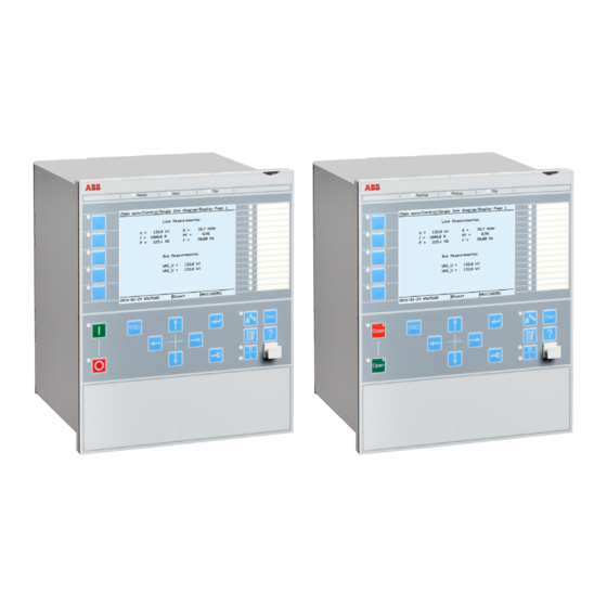
AMU0600442 v14 IEC13000239-3-en.vsd IEC13000239 V3 EN-US Figure 23: Local human-machine interface The LHMI of the IED contains the following elements: • Keypad • Display (LCD) • LED indicators • Communication port for PCM600 Transformer protection RET650 2.2 IEC Application manual... -
Page 72: Display
4 Scroll bar (appears when needed) The function key button panel shows on request what actions are possible with the function buttons. Each function button has a LED indication that can be used as a Transformer protection RET650 2.2 IEC Application manual... - Page 73 Each panel is shown by pressing one of the function buttons or the Multipage button. Pressing the ESC button clears the panel from the display. Both panels have a dynamic width that depends on the label string length. Transformer protection RET650 2.2 IEC Application manual...
-
Page 74: Leds
. These LEDs can indicate the status of two arbitrary binary signals by configuring the OPENCLOSE_LED function block. For instance, OPENCLOSE_LED can be connected to a circuit breaker to indicate the breaker open/close status on the LEDs. Transformer protection RET650 2.2 IEC Application manual... -
Page 75: Keypad
The push-buttons are also used to acknowledge alarms, reset indications, provide help and switch between local and remote control mode. The keypad also contains programmable push-buttons that can be configured either as menu shortcut or control buttons. Transformer protection RET650 2.2 IEC Application manual... - Page 76 Figure 28: LHMI keypad with object control, navigation and command push- buttons and RJ-45 communication port 1...5 Function button Close Open Escape Left Down Right Enter Remote/Local Uplink LED Not in use Multipage Menu Transformer protection RET650 2.2 IEC Application manual...
-
Page 77: Local Hmi Functionality
The blocking of functions through the IEC61850 protocol can be reset in Main menu/Test/Reset IEC61850 Mod. The yellow LED changes to either On or Off state depending on the state of operation. Transformer protection RET650 2.2 IEC Application manual... -
Page 78: Parameter Management
Numerical values are presented either in integer or in decimal format with minimum and maximum values. Character strings can be edited character by character. Enumerated values have a predefined set of selectable values. Transformer protection RET650 2.2 IEC Application manual... -
Page 79: Front Communication
Do not connect the IED front port to a LAN. Connect only a single local PC with PCM600 to the front port. It is only intended for temporary use, such as commissioning and testing. Transformer protection RET650 2.2 IEC Application manual... -
Page 81: Section 6 Differential Protection
For this reason it is important that the differential protection has a high level of sensitivity and that it is possible to use a sensitive setting without causing unwanted operations during external faults. Transformer protection RET650 2.2 IEC Application manual... -
Page 82: Setting Guidelines
The protection should be provided with a proportional bias, which makes the protection operate for a certain Transformer protection RET650 2.2 IEC Application manual... - Page 83 Transformers can be connected to buses in such ways that the current transformers used for the differential protection will be either in series with the power Transformer protection RET650 2.2 IEC Application manual...
- Page 84 For differential applications on HV shunt reactors, due to the fact that there is no heavy through-fault condition, the unrestrained differential operation level can be set to IdUnre = 1.75pu The overall operating characteristic of the transformer differential protection is shown in figure 30. Transformer protection RET650 2.2 IEC Application manual...
-
Page 85: Elimination Of Zero Sequence Currents
This is the case when zero sequence current cannot be properly transformed to the other side of the power transformer. Power Transformer protection RET650 2.2 IEC Application manual... -
Page 86: Inrush Restraint Methods
Transformers likely to be exposed to overvoltage or underfrequency conditions (that is, generator step-up transformers in power stations) should be provided with a dedicated overexcitation protection based on V/Hz to achieve a trip before the core thermal limit is reached. Transformer protection RET650 2.2 IEC Application manual... -
Page 87: Cross-Blocking Between Phases
It can be selected in the range from 30 degrees to 90 degrees, with a step of 1 degree. The default value is 60 degrees. The default setting 60 degrees somewhat favors Transformer protection RET650 2.2 IEC Application manual... - Page 88 The directional comparisons which are possible, are: W1 - (W2+W3) and W2 - (W1+W3). The rule applied by the internal/external fault discriminator in case of three-winding power transformers is: Transformer protection RET650 2.2 IEC Application manual...
-
Page 89: Differential Current Alarm
OpenCTIN: Open CT in CT group inputs (1 for input 1 and 2 for input 2) • OpenCTPH: Open CT with phase information (1 for phase L1, 2 for phase L2, 3 for phase L3) Transformer protection RET650 2.2 IEC Application manual... -
Page 90: Switch Onto Fault Feature
In such cases the ratio for the main CT connected in delta shall be intentionally set for √(3)=1.732 times smaller than actual ratio of individual phase CTs (for example, instead of 800/5 set 462/5) In case the ratio is 800/2.88A, Transformer protection RET650 2.2 IEC Application manual... -
Page 91: Typical Main Ct Connections For Transformer Differential Protection
31, shall be set ToObject. If star connected main CTs have their star point away from the protected transformer this parameter should be set FromObject. For delta DAC connected main CTs, secondary currents fed to the IED: Transformer protection RET650 2.2 IEC Application manual... -
Page 92: Application Examples
Example 1: Star-delta connected power transformer without on-load tap-changer SEMOD167854-110 v5 Single line diagrams for two possible solutions for such type of power transformer with all relevant application data are given in figure 32. Transformer protection RET650 2.2 IEC Application manual... - Page 93 3. For star connected CTs make sure how they are stared (that is, earthed) to/from protected transformer. 4. Enter the following settings for all three CT input channels used for the LV side CTs see table 10. Transformer protection RET650 2.2 IEC Application manual...
- Page 94 CTPrim / GlobalBaseSelW3 (CTPrim / GlobalBaseSelW3) / sqrt(3) ConnectTypeW1 STAR (Y) STAR (Y) ConnectTypeW2 delta=d star=y ClockNumberW2 1 [30 deg lag] 0 [0 deg] ZSCurrSubtrW1 ZSCurrSubtrW2 TconfigForW1 TconfigForW2 Table continues on next page Transformer protection RET650 2.2 IEC Application manual...
- Page 95 24.9 kV currents are rotated by 30° in anti-clockwise direction. Thus, the DAB CT delta connection (see figure 33) must be used for 24.9 kV CTs in order to put 115 kV & 24.9 kV currents in phase. Transformer protection RET650 2.2 IEC Application manual...
- Page 96 (star conected CT) Solution 2 (delta connected RatedVoltageW1 115 kV 115 kV Rated VoltageW2 24.9 kV 24.9 kV RatedCurrentW1 301 A 301 A RatedCurrentW2 1391 A 1391 A Table continues on next page Transformer protection RET650 2.2 IEC Application manual...
-
Page 97: Summary And Conclusions
The following table summarizes the most commonly used star-delta vector groups around the world and provides information about the required type of main CT delta connection on the star side of the protected transformer. Transformer protection RET650 2.2 IEC Application manual... - Page 98 IED YNd1 DAC/Yy0 IEC06000559 V1 EN-US Dyn1 DAB/Yy0 IEC06000560 V1 EN-US YNd11 DAB/Yy0 IEC06000561 V1 EN-US Dyn11 DAC/Yy0 IEC06000562 V1 EN-US YNd5 DAB/Yy6 IEC06000563 V1 EN-US Dyn5 DAC/Yy6 IEC06000564 V1 EN-US Transformer protection RET650 2.2 IEC Application manual...
-
Page 99: Low Impedance Restricted Earth Fault Protection Refpdif
The restricted earth fault protection is not affected, as a differential protection, with the following power transformer related phenomena: Transformer protection RET650 2.2 IEC Application manual... -
Page 100: Transformer Winding, Solidly Earthed
A common application is for low reactance earthed transformer where the earthing is through separate zig-zag earthing transformers. The fault current is then limited to typical 800 to 2000 A for each transformer. The connection for this application is shown in figure 35. Transformer protection RET650 2.2 IEC Application manual... -
Page 101: Autotransformer Winding, Solidly Earthed
REFPDIF. The complete transformer will then be protected including the HV side, the neutral connection and the LV side. The connection of REFPDIF for this application is shown in figure 36. Transformer protection RET650 2.2 IEC Application manual... -
Page 102: Reactor Winding, Solidly Earthed
REFPDIF for an autotransformer, solidly earthed 6.2.2.4 Reactor winding, solidly earthed M13048-18 v10 Reactors can be protected with restricted earth-fault protection, low impedance function REFPDIF. The connection of REFPDIF for this application is shown in figure 37. Transformer protection RET650 2.2 IEC Application manual... -
Page 103: Multi-Breaker Applications
The second winding set is only applicable for autotransformers. A typical connection for a star-delta transformer is shown in figure 38. Transformer protection RET650 2.2 IEC Application manual... -
Page 104: Ct Earthing Direction
I3PW1CT2: Phase currents for winding1 second current transformer set for multi- breaker arrangements. When not required configure input to "GRP-OFF". I3PW2CT1: Phase currents for winding 2 first current transformer set. Used for autotransformers. Transformer protection RET650 2.2 IEC Application manual... -
Page 105: Settings
The stabilizing can then be high so an unnecessary high fault level can be required. The setting is normally 1.0 but in multi-breaker arrangement the setting shall be CT primary rating/IBase. Transformer protection RET650 2.2 IEC Application manual... - Page 106 CT primary rating/IBase. CTFactorSec1: See setting CTFactorPri1. Only difference is that CTFactorSec1 is related to W2 side. CTFactorSec2: See setting CTFactorPri2. Only difference is that CTFactorSec2 is related to W2 side. Transformer protection RET650 2.2 IEC Application manual...
-
Page 107: Section 7 Current Protection
(and relay) point, for which very high fault currents are characteristic. The instantaneous phase overcurrent protection PHPIOC can operate in 10 ms for faults characterized by very high currents. Transformer protection RET650 2.2 IEC Application manual... -
Page 108: Setting Guidelines
The following fault calculations have to be done for three-phase, single-phase-to- earth and two-phase-to-earth faults. With reference to Figure 39, apply a fault in B and then calculate the current through-fault phase current I . The calculation Transformer protection RET650 2.2 IEC Application manual... - Page 109 5% for the maximum possible transient overreach have to be introduced. An additional 20% is suggested due to the inaccuracy of the instrument transformers under transient conditions and inaccuracy in the system data. Transformer protection RET650 2.2 IEC Application manual...
-
Page 110: Meshed Network With Parallel Line
C point with the C breaker open. A fault in C has to be applied, and then the maximum current seen from the IED ) on the healthy line (this applies for single-phase-to-earth and two-phase-to- earth faults) is calculated. Transformer protection RET650 2.2 IEC Application manual... - Page 111 The IED setting value IP>> is given in percentage of the primary base current value, IBase. The value for IP>> is given from this formula: >>= × IBase (Equation 19) EQUATION1147 V3 EN-US Transformer protection RET650 2.2 IEC Application manual...
-
Page 112: Directional Phase Overcurrent Protection, Four Steps Oc4Ptoc
The selectivity between different overcurrent protections is normally enabled by co-ordination between the function time delays of the different protections. To enable optimal co-ordination between all overcurrent Transformer protection RET650 2.2 IEC Application manual... -
Page 113: Setting Guidelines
The parameters for the directional phase overcurrent protection, four steps OC4PTOC are set via the local HMI or PCM600. The following settings can be done for OC4PTOC. Transformer protection RET650 2.2 IEC Application manual... - Page 114 7% of IB. 2ndHarmStab: Operate level of 2nd harmonic current restrain set in % of the fundamental current. The setting range is 5 - 100% in steps of 1%. The default setting is 20%. Transformer protection RET650 2.2 IEC Application manual...
-
Page 115: Settings For Each Step
DirModex: The directional mode of step x. Possible settings are Off/Non- directional/Forward/Reverse. Characteristx: Selection of time characteristic for step x. Definite time delay and different types of inverse time characteristics are available according to Table 15. Transformer protection RET650 2.2 IEC Application manual... - Page 116 By setting this parameter the operation time of the step can never be shorter than the setting. Setting range: 0.000 - 60.000s in steps of 0.001s. Transformer protection RET650 2.2 IEC Application manual...
- Page 117 (1), IEC (2 = set constant time reset) and ANSI (3 = current dependent reset time). For IEC inverse time characteristics, the possible delay time settings are instantaneous (1) and IEC (2 = set constant time reset). Transformer protection RET650 2.2 IEC Application manual...
-
Page 118: Setting Example
The protection reset current must also be considered so that a short peak of overcurrent does not cause the operation of a protection even when the overcurrent has ceased. This phenomenon is described in Figure 45. Transformer protection RET650 2.2 IEC Application manual... - Page 119 The maximum load current on the line has to be estimated. There is also a demand that all faults within the zone that the protection shall cover must be detected by the phase overcurrent protection. The minimum fault current Iscmin to be detected by Transformer protection RET650 2.2 IEC Application manual...
- Page 120 This is mostly used in the case of inverse time overcurrent protection. Figure shows how the time-versus-current curves are plotted in a diagram. The time setting is chosen to get the shortest fault time with maintained selectivity. Transformer protection RET650 2.2 IEC Application manual...
- Page 121 These time delays can vary significantly between different protective equipment. The following time delays can be estimated: Protection operation 15-60 ms time: Protection resetting time: 15-60 ms Breaker opening time: 20-120 ms Transformer protection RET650 2.2 IEC Application manual...
- Page 122 There are uncertainties in the values of protection operation time, breaker opening time and protection resetting time. Therefore a safety margin has to be included. With normal values the needed time difference can be calculated according to Equation 25. Transformer protection RET650 2.2 IEC Application manual...
-
Page 123: Instantaneous Residual Overcurrent Protection Efpioc
Some guidelines for the choice of setting parameter for EFPIOC is given. M12762-6 v8 Common base IED values for primary current (IBase), primary voltage (UBase) and primary power (SBase) are set in the global base values for settings function GBASVAL. Transformer protection RET650 2.2 IEC Application manual... - Page 124 The function shall not operate for any of the calculated currents to the protection. The minimum theoretical current setting (Imin) will be: in MAX I (Equation 26) EQUATION284 V2 EN-US Transformer protection RET650 2.2 IEC Application manual...
- Page 125 = 1.3 × I (Equation 29) EQUATION288 V3 EN-US The IED setting value IN>> is given in percent of the primary base current value, IBase. The value for IN>> is given by the formula: Transformer protection RET650 2.2 IEC Application manual...
-
Page 126: Directional Residual Overcurrent Protection, Four Steps Ef4Ptoc
EF4PTOC 51N_67N 4(IN>) protection, four steps TEF-REVA V2 EN-US 7.4.2 Application M12509-12 v10 The directional residual overcurrent protection, four steps EF4PTOC is used in several applications in the power system. Some applications are: Transformer protection RET650 2.2 IEC Application manual... - Page 127 Time characteristics Curve name ANSI Extremely Inverse ANSI Very Inverse ANSI Normal Inverse ANSI Moderately Inverse ANSI/IEEE Definite time ANSI Long Time Extremely Inverse ANSI Long Time Very Inverse Table continues on next page Transformer protection RET650 2.2 IEC Application manual...
-
Page 128: Setting Guidelines
Thus, if only the inverse time delay is required, it is important to set the definite time delay for that stage to zero. Transformer protection RET650 2.2 IEC Application manual... -
Page 129: Common Settings For All Steps
IN>Dir IEC05000135-5-en.vsdx IEC05000135 V5 EN-US Figure 51: Relay characteristic angle given in degree In a normal transmission network a normal value of RCA is about 65°. The setting range is -180° to +180°. Transformer protection RET650 2.2 IEC Application manual... -
Page 130: 2Nd Harmonic Restrain
This will give a declining residual current in the network, as the inrush current is deviating between the phases. There is a risk that the residual overcurrent function will give an unwanted trip. The inrush current has a relatively large ratio of 2nd Transformer protection RET650 2.2 IEC Application manual... -
Page 131: Parallel Transformer Inrush Current Logic
Also the same current setting as this step is chosen for the blocking at parallel transformer energizing. The settings for the parallel transformer logic are described below. BlkParTransf: This is used to On blocking at energising of parallel transformers. Transformer protection RET650 2.2 IEC Application manual... -
Page 132: Switch Onto Fault Logic
The function can be activated by Circuit breaker position (change) or Circuit breaker command. tUnderTime: Time delay for operation of the sensitive undertime function. The setting range is 0.000 - 60.000 s in step of 0.001 s. The default setting is 0.300 s Transformer protection RET650 2.2 IEC Application manual... -
Page 133: Settings For Each Step (X = 1, 2, 3 And 4)
: Minimum operate current for step in % of IB. Set below INx> for every step to achieve ANSI reset characteristic according to standard. If is set above INx> for any step, signal will reset at current equals to zero. Transformer protection RET650 2.2 IEC Application manual... - Page 134 HarmBlockx: This is used to enable block of step x from 2 harmonic restrain function. tPCrvx, tACrvx, tBCrvx, tCCrvx: Parameters for user programmable of inverse time characteristic curve. The time characteristic equation is according to equation 31: Transformer protection RET650 2.2 IEC Application manual...
-
Page 135: Transformer Application Example
Three phase CT summated Single CT IN> en05000490.vsd IEC05000490 V1 EN-US Figure 54: Residual overcurrent protection application on a directly earthed transformer winding In this case the protection has two different tasks: Transformer protection RET650 2.2 IEC Application manual... - Page 136 In the calculation of the fault current fed to the protection, at different earth faults, are highly dependent on the positive and zero sequence source impedances, as well as the division of residual current in the network. Earth-fault current calculations are necessary for the setting. Transformer protection RET650 2.2 IEC Application manual...
- Page 137 2) of about 0.5 s the current setting must be set so high so that such faults does not cause unwanted step 1 trip. Therefore, a fault calculation as shown in Figure is made. Transformer protection RET650 2.2 IEC Application manual...
- Page 138 Such currents can be due to un-transposed lines. In case to protection of transformer windings not feeding residual current at external earth faults, a fast low current step can be acceptable. Transformer protection RET650 2.2 IEC Application manual...
-
Page 139: Thermal Overload Protection, Two Time Constants Trpttr
Both the permissive steady state loading level as well as the thermal time constant is influenced by the cooling system of the transformer. The two parameters sets can be activated by the binary input signal COOLING. This Transformer protection RET650 2.2 IEC Application manual... -
Page 140: Setting Guideline
(OA). IBase2: Base current for setting given as percentage of IBase. This setting shall be related to the status with activated COOLING input. It is suggested to give a Transformer protection RET650 2.2 IEC Application manual... - Page 141 ILowTau2. ILowTau2 is set in % of IBase2. The possibility to change time constant with the current value as the base can be useful in different applications. Below some examples are given: Transformer protection RET650 2.2 IEC Application manual...
-
Page 142: Breaker Failure Protection Ccrbrf
Breaker failure protection CCRBRF IP14514-1 v6 7.6.1 Identification M14878-1 v5 Function description IEC 61850 IEC 60617 ANSI/IEEE C37.2 identification identification device number Breaker failure protection, 3-phase CCRBRF 50BF activation and output 3I>BF SYMBOL-U V1 EN-US Transformer protection RET650 2.2 IEC Application manual... -
Page 143: Application
CB Pos Check (circuit breaker position check) and Contact means re-trip is done when circuit breaker is closed (breaker position is used). No CBPos Check means re-trip is done without any check of breaker position. Transformer protection RET650 2.2 IEC Application manual... - Page 144 Also in effectively earthed systems the setting of the earth-fault current protection can be chosen to relatively low current level. The Transformer protection RET650 2.2 IEC Application manual...
- Page 145 It is often required that the total fault clearance time shall be less than a given critical time. This time is often dependent of the ability to maintain transient stability in case of a fault close to a power plant. Transformer protection RET650 2.2 IEC Application manual...
-
Page 146: Pole Discordance Protection Ccpdsc
Trip pulse duration. This setting must be larger than the critical impulse time of circuit breakers to be tripped from the breaker failure protection. Typical setting is 200 ms. Pole discordance protection CCPDSC IP14516-1 v5 Transformer protection RET650 2.2 IEC Application manual... -
Page 147: Identification
The following settings can be done for the pole discordance protection. GlobalBaseSel: Selects the global base value group used by the function to define IBase, UBase and SBase as applicable. Operation: Off or On Transformer protection RET650 2.2 IEC Application manual... - Page 148 This is due to the existence of low impedance current paths in the switch yard. This phenomenon must be considered in the setting of the parameter. CurrRelLevel: Current magnitude for release of the function in % of IBase. Transformer protection RET650 2.2 IEC Application manual...
-
Page 149: Section 8 Voltage Protection
Disconnect apparatuses, like electric motors, which will be damaged when subject to service under low voltage conditions. The function has a high measuring accuracy and a settable hysteresis to allow applications to control reactive load. Transformer protection RET650 2.2 IEC Application manual... -
Page 150: Setting Guidelines
8.1.3.5 Backup protection for power system faults M13851-62 v3 The setting must be below the lowest occurring "normal" voltage and above the highest occurring voltage during the fault conditions under consideration. Transformer protection RET650 2.2 IEC Application manual... -
Page 151: Settings For Two Step Undervoltage Protection
When using inverse time characteristic for the undervoltage function during very low voltages can give a short operation time. This might lead to unselective tripping. By setting t1Min longer than the operation time for other protections, such unselective tripping can be avoided. Transformer protection RET650 2.2 IEC Application manual... -
Page 152: Two Step Overvoltage Protection Ov2Ptov
Two step overvoltage protection OV2PTOV IP14545-1 v3 8.2.1 Identification M17002-1 v8 Function description IEC 61850 IEC 60617 identification ANSI/IEEE C37.2 identification device number Two step overvoltage protection OV2PTOV 3U> SYMBOL-C-2U-SMALLER-THAN V2 EN-US Transformer protection RET650 2.2 IEC Application manual... -
Page 153: Application
The same also applies to the associated equipment, its voltage and time characteristic. There are wide applications where general overvoltage functions are used. All voltage related settings are made as a percentage of a settable base primary voltage, Transformer protection RET650 2.2 IEC Application manual... -
Page 154: Equipment Protection, Such As For Motors, Generators, Reactors And Transformers
The following settings can be done for the two step overvoltage protection M13852-22 v10 ConnType: Sets whether the measurement shall be phase-to-earth fundamental value, phase-to-phase fundamental value, phase-to-earth RMS value or phase-to- phase RMS value. Transformer protection RET650 2.2 IEC Application manual... - Page 155 The speed might be important for example in case of protection of transformer that might be overexcited. The time delay must be co- ordinated with other automated actions in the system. Transformer protection RET650 2.2 IEC Application manual...
- Page 156 If the function is used as control for automatic switching of reactive compensation devices the hysteresis must be set smaller than the voltage change after switching of the compensation device. Transformer protection RET650 2.2 IEC Application manual...
-
Page 157: Two Step Residual Overvoltage Protection Rov2Ptov
The time delay for ROV2PTOV is seldom critical, since residual voltage is related to earth faults in a high-impedance earthed system, and enough time must normally be given for the primary protection to clear the fault. In some more specific Transformer protection RET650 2.2 IEC Application manual... -
Page 158: Equipment Protection, Such As For Motors, Generators, Reactors And Transformersequipment Protection For Transformers
The two healthy phases will measure full phase-to- phase voltage, as the faulty phase will be connected to earth. The residual overvoltage will be three times the phase-to-earth voltage. See figure 59. Transformer protection RET650 2.2 IEC Application manual... -
Page 159: Direct Earthed System
The other healthy phase will still have normal phase-to-earth voltage. The residual sum will have the same value as the remaining phase-to-earth voltage, which is shown in Figure 60. IEC07000189-2-en.vsd IEC07000189 V2 EN-US Figure 60: Earth fault in Direct earthed system Transformer protection RET650 2.2 IEC Application manual... -
Page 160: Settings For Two Step Residual Overvoltage Protection
The setting is highly dependent on the protection application. In many applications, the protection function has the task to prevent damage to the protected object. The speed might be important, for Transformer protection RET650 2.2 IEC Application manual... - Page 161 Make sure that the set value for parameter HystABSn is somewhat smaller than the set pickup value. Otherwise there is a risk that step n will not reset properly. Transformer protection RET650 2.2 IEC Application manual...
-
Page 162: Overexcitation Protection Oexpvph
110% of rated value at no load. The capability of a transformer (or generator) to withstand overexcitation can be illustrated in the form of a thermal capability curve, that is, a diagram which shows Transformer protection RET650 2.2 IEC Application manual... - Page 163 It then uses the positive sequence quantities of voltages and currents. Analog measurements shall not be taken from any winding where a load tap changer is located. Some different connection alternatives are shown in figure 61. Transformer protection RET650 2.2 IEC Application manual...
-
Page 164: Setting Guidelines
START: The START output indicates that the level V/Hz>> has been reached. It can be used to initiate time measurement. TRIP: The TRIP output is activated after the operate time for the U/f level has expired. TRIP signal is used to trip the circuit breaker(s). Transformer protection RET650 2.2 IEC Application manual... -
Page 165: Settings
The default value is recommended to be used if the constant is not known. tMin: The operating times at voltages higher than the set V/Hz>>. The setting shall match capabilities on these high voltages. Typical setting can be 1-10 second. Transformer protection RET650 2.2 IEC Application manual... -
Page 166: Service Value Report
In this example, each step will be (140-105) /5 = 7%. The setting of time delays t1 to t6 are listed in table 19. Transformer protection RET650 2.2 IEC Application manual... - Page 167 V/Hz transformer capability curve relay operate characteristic Continous 0.05 Time (minutes) en01000377.vsd IEC01000377 V1 EN-US Figure 62: Example on overexcitation capability curve and V/Hz protection settings for power transformer Transformer protection RET650 2.2 IEC Application manual...
-
Page 169: Section 9 Frequency Protection
M13355-3 v8 All the frequency and voltage magnitude conditions in the system where SAPTUF performs its functions should be considered. The same also applies to the associated equipment, its frequency and time characteristic. Transformer protection RET650 2.2 IEC Application manual... -
Page 170: Overfrequency Protection Saptof
Overfrequency protection SAPTOF IP15747-1 v3 9.2.1 Identification M14866-1 v4 Function description IEC 61850 IEC 60617 ANSI/IEEE C37.2 identification identification device number Overfrequency protection SAPTOF f > SYMBOL-O V1 EN-US Transformer protection RET650 2.2 IEC Application manual... -
Page 171: Application
In smaller systems the frequency START level has to be set at a higher value, and the time delay must be rather short. Transformer protection RET650 2.2 IEC Application manual... -
Page 172: Rate-Of-Change Of Frequency Protection Sapfrc
SAPFRC is normally used together with an overfrequency or underfrequency function, in small power systems, where a single event can cause a large imbalance Transformer protection RET650 2.2 IEC Application manual... - Page 173 - up to 3 Hz/s has been experienced when a small island was isolated from a large system. For more "normal" severe disturbances in large power systems, rate-of-change of frequency is much less, most often just a fraction of 1.0 Hz/s. Transformer protection RET650 2.2 IEC Application manual...
-
Page 175: Section 10 Secondary System Supervision
10.1.3 Setting guidelines M12397-17 v8 GlobalBaseSel: Selects the global base value group used by the function to define IBase, UBase and SBase as applicable. Transformer protection RET650 2.2 IEC Application manual... -
Page 176: Fuse Failure Supervision Fufspvc
These solutions are combined to get the best possible effect in the fuse failure supervision function (FUFSPVC). FUFSPVC function built into the IED products can operate on the basis of external binary signals from the miniature circuit breaker or from the line disconnector. The Transformer protection RET650 2.2 IEC Application manual... -
Page 177: Setting Guidelines
We propose a setting of approximately 70% of UBase. The drop off time of 200 ms for dead phase detection makes it recommended to always set SealIn to On since this will secure a fuse failure indication at persistent Transformer protection RET650 2.2 IEC Application manual... -
Page 178: Negative Sequence Based
The setting of the current limit 3I2< is in percentage of parameter IBase. The setting of 3I2< must be higher than the normal unbalance current that might exist in the system and can be calculated according to equation 41. Transformer protection RET650 2.2 IEC Application manual... -
Page 179: Zero Sequence Based
10.2.3.5 Delta U and delta I GUID-02336F26-98C0-419D-8759-45F5F12580DE v7 Set the operation mode selector OpDUDI to On if the delta function shall be in operation. Transformer protection RET650 2.2 IEC Application manual... -
Page 180: Dead Line Detection
(mutual coupling to the other phases). Set the UDLD< with a sufficient margin below the minimum expected operating voltage. A safety margin of at least 15% is recommended. Transformer protection RET650 2.2 IEC Application manual... -
Page 181: Section 11 Control
The commands to an apparatus can be initiated from the Control Centre (CC), the station HMI or the local HMI on the IED front. Transformer protection RET650 2.2 IEC Application manual... - Page 182 The apparatus control function is realized by means of a number of function blocks designated: • Switch controller SCSWI • Circuit breaker SXCBR • Bay control QCBAY • Local remote LOCREM • Local remote control LOCREMCTRL Transformer protection RET650 2.2 IEC Application manual...
- Page 183 Figure 65. IEC 61850 -QB1 QCBAY SXCBR SCSWI SXCBR -QA1 SXCBR SCILO -QB9 IEC17000061=1=en=Orignal.ai IEC17000061 V1 EN-US Figure 64: Signal flow between apparatus control function blocks when all functions are situated within the IED Transformer protection RET650 2.2 IEC Application manual...
- Page 184 IED, then the local/remote switch is under authority control, otherwise the default user can perform control operations from the local IED HMI without logging in. The default position of the local/remote switch is on remote. Transformer protection RET650 2.2 IEC Application manual...
-
Page 185: Bay Control Qcbay
The Bay control (QCBAY) is used to handle the selection of the operator place per bay. The function gives permission to operate from two main types of locations either from Remote (for example, control centre or station HMI) or from Local Transformer protection RET650 2.2 IEC Application manual... -
Page 186: Switch Controller Scswi
SCSWI may handle and operate on one three-phase device or three one-phase switching devices. After the selection of an apparatus and before the execution, the switch controller performs the following checks and actions: Transformer protection RET650 2.2 IEC Application manual... -
Page 187: Switches Sxcbr
Substitution of position indication • Supervision timer that the primary device starts moving after a command • Supervision of allowed time for intermediate position • Definition of pulse duration for open/close command respectively Transformer protection RET650 2.2 IEC Application manual... -
Page 188: Proxy For Signals From Switching Device Via Goose Xlnproxy
XLNPROXY function, their usage is controlled by the connection of each data’s signal input and valid input. These connections are usually from the GOOSEXLNRCV function (see Figure and Figure 68). Transformer protection RET650 2.2 IEC Application manual... - Page 189 Section 11 1MRK 504 169-UEN A Control IEC16000071 V1 EN-US Figure 67: Configuration with XLNPROXY and GOOSEXLNRCV where all the IEC 61850 modelled data is used, including selection Transformer protection RET650 2.2 IEC Application manual...
- Page 190 SCSWI function. This cause is also shown on the output L_CAUSE as indicated in the following table: Transformer protection RET650 2.2 IEC Application manual...
-
Page 191: Interaction Between Modules
• The logical node Interlocking (SCILO) provides the information to SCSWI whether it is permitted to operate due to the switchyard topology. The Transformer protection RET650 2.2 IEC Application manual... - Page 192 (energizing-check) is included. • The Generic Automatic Process Control function, GAPC, handles generic commands from the operator to the system. The overview of the interaction between these functions is shown in Figure below. Transformer protection RET650 2.2 IEC Application manual...
-
Page 193: Setting Guidelines
Figure 69: Example overview of the interactions between functions in a typical 11.1.3 Setting guidelines M16669-3 v4 The setting parameters for the apparatus control function are set via the local HMI or PCM600. Transformer protection RET650 2.2 IEC Application manual... -
Page 194: Bay Control (Qcbay)
When the time has expired, the control function is reset, and a cause-code is given. tSynchrocheck is the allowed time for the synchrocheck function to fulfill the close conditions. When the time has expired, the function tries to start the synchronizing Transformer protection RET650 2.2 IEC Application manual... -
Page 195: Switch (Sxcbr)
If AdaptivePulse is set to Adaptive, it is the maximum length of the output pulse for an open command. The default length is set to 200 ms for a circuit breaker (SXCBR). Transformer protection RET650 2.2 IEC Application manual... -
Page 196: Proxy For Signals From Switching Device Via Goose Xlnproxy
Function description IEC 61850 IEC 60617 ANSI/IEEE C37.2 identification identification device number Automatic voltage control for tap TR1ATCC changer, single control IEC10000165 V1 EN-US Tap changer control and supervision, 6 TCMYLTC binary inputs Transformer protection RET650 2.2 IEC Application manual... -
Page 197: Application
IEC 61850-8-1: • Automatic voltage control for tap changer, TR1ATCC for single control and TR8ATCC for parallel control. • Tap changer control and supervision, 6 binary inputs, TCMYLTC and 32 binary inputs, TCLYLTC Transformer protection RET650 2.2 IEC Application manual... - Page 198 In normal applications, the LV side of the transformer is used as the voltage measuring point. If necessary, the LV side current is used as load current to calculate the line-voltage drop to the regulation point. Transformer protection RET650 2.2 IEC Application manual...
- Page 199 3ph or ph-ph or 1ph Voltage Low Voltage Side (Busbar Voltage) Line Impedance R+jX Load Center UL (Load Point Voltage) IEC10000044-2-en.vsd IEC10000044 V2 EN-US Figure 70: Signal flow for a single transformer with voltage control Transformer protection RET650 2.2 IEC Application manual...
- Page 200 (interval between U1 and U2 in figure 71). In that case no actions will be taken by TR1ATCC. However, if U becomes smaller than U1, or greater than U2, an appropriate raise or lower timer will start. The timer will run as long as the Transformer protection RET650 2.2 IEC Application manual...
- Page 201 This setting should be coordinated with the tap changer mechanism operation time. Constant (definite) time delay is independent of the voltage deviation. The inverse time characteristic for the first time delay follows the formulas: Transformer protection RET650 2.2 IEC Application manual...
- Page 202 The second time delay, t2, will be used for consecutive commands (commands in the same direction as the first command). It can have a definite or inverse time characteristic according to the setting t2Use (Constant/Inverse). Inverse time Transformer protection RET650 2.2 IEC Application manual...
- Page 203 However, a situation where U >U can be caused by a capacitive load condition, and if the wish is to allow for a situation like that, the limitation can be removed by setting the parameter OperCapaLDC to Transformer protection RET650 2.2 IEC Application manual...
- Page 204 LVARESET in TR1ATCC or TR8ATCC block, brings the voltage setpoint back to USet. With these factors, TR1ATCC or TR8ATCC adjusts the value of the set voltage USet according to the following formula: Transformer protection RET650 2.2 IEC Application manual...
- Page 205 This is unavoidable and is due to small inequalities in measurement and so on. The one tap changer that responds first on a low voltage condition with a Transformer protection RET650 2.2 IEC Application manual...
- Page 206 When the selection of master or follower in parallel control, or automatic control in single mode, is made with a three position switch in the substation, an arrangement as in figure below is arranged with application configuration. Transformer protection RET650 2.2 IEC Application manual...
- Page 207 The tap positions will diverge and finally end up in a runaway tap situation if no measures to avoid this are taken. Transformer protection RET650 2.2 IEC Application manual...
- Page 208 Vector diagram for two transformers regulated exactly on target voltage. A comparison with figure gives that the line voltage drop compensation for the purpose of reverse reactance control is made with a value with opposite sign on X Transformer protection RET650 2.2 IEC Application manual...
- Page 209 T1 will be the one to tap down, and when the busbar voltage decreases, T2 will be the one to tap up. The overall performance will then be that the runaway tap situation will be avoided and that the circulating current will be minimized. Transformer protection RET650 2.2 IEC Application manual...
- Page 210 HMI as a service Bmean value BusVolt under Main menu/Test/Function status/Control/ TransformerVoltageControl(ATCC,90). Measured current values for the individual transformers must be communicated between the participating TR8ATCC functions, in order to calculate the circulating current. Transformer protection RET650 2.2 IEC Application manual...
- Page 211 This is set On/Off by setting parameter OperUsetPar. The calculated mean USet value is shown on the local HMI as a service value USETPAR under Main menu/Test/Function status/ Control/TransformerVoltageControl(ATCC,90). Transformer protection RET650 2.2 IEC Application manual...
- Page 212 (with or without an offset) of the master. The setting parameter tAutoMSF then introduces a time delay on UVRAISE/ULOWER commands individually for each follower, and effectively this can be used to avoid simultaneous tapping. Homing SEMOD159053-200 v2 Transformer protection RET650 2.2 IEC Application manual...
- Page 213 As the name indicates they will adapt to the manual tapping of the transformer that has been put in manual mode. Transformer protection RET650 2.2 IEC Application manual...
- Page 214 ATCCs with regard to the calculation of circulating currents. The capacitive current is part of the imaginary load current and therefore essential in the calculation. The calculated circulating current and the real circulating currents Transformer protection RET650 2.2 IEC Application manual...
- Page 215 ATCC this is made numerically. The reactive power of the capacitor bank is given as a setting Q1, which makes it possible to calculate the reactive capacitance: Transformer protection RET650 2.2 IEC Application manual...
- Page 216 HV-side to the LV-side as shown in figure 79. The reactive power Q is forward when the total load on the LV side is inductive ( reactance) as shown in figure 79. Transformer protection RET650 2.2 IEC Application manual...
- Page 217 T3 is disconnected which will lead to T3 sending the DISC=1 signal to the other two parallel TR8ATCC modules (T1 and T2) in the group. Also see table 26. Transformer protection RET650 2.2 IEC Application manual...
- Page 218 One is the data set that needs to be transmitted to other TR8ATCC blocks in the same parallel group, and the other is the data set that is transferred to the TCMYLTC or TCLYLTC function block for the same transformer as TR8ATCC block belongs to. Transformer protection RET650 2.2 IEC Application manual...
- Page 219 Manual configuration of VCTR GOOSE data set is required. Note that both data value attributes and quality attributes have to be mapped. The following data objects must be configured: • BusV • LodAIm • LodARe • PosRel • SetV • VCTRStatus • Transformer protection RET650 2.2 IEC Application manual...
- Page 220 Partial Block: Prevents operation of the tap changer only in one direction (only URAISE or ULOWER command is blocked) in manual and automatic control mode. Auto Block: Prevents automatic voltage regulation, but the tap changer can still be controlled manually. Transformer protection RET650 2.2 IEC Application manual...
- Page 221 REVACBLK will be set. The reversed action feature can be turned off/on OperationRA . with the setting parameter Table continues on next page Transformer protection RET650 2.2 IEC Application manual...
- Page 222 This error condition can be reset by the input RESETERR on TCMYLTC function block, or alternatively by changing control mode of TR1ATCC or TR8ATCC function to Manual and then back to Automatic. Table continues on next page Transformer protection RET650 2.2 IEC Application manual...
- Page 223 OUTOFPOS and AUTOBLK (alternatively an alarm) will be set. Setting parameters for blocking that can be set in TR1ATCC or TR8ATCC under setting group Nx in PST/ local HMI are listed in table 28. Transformer protection RET650 2.2 IEC Application manual...
- Page 224 The output AUTOBLK will be activated. Deblocking is made via the input DEBLKAUT. Blockings activated by the operating conditions, without setting or separate external activation possibilities, are listed in table 30. Transformer protection RET650 2.2 IEC Application manual...
- Page 225 TR8ATCCs that is, all units of the parallel group. The following conditions in any one of TR8ATCCs in the group will cause mutual blocking when the circulating current method is used: Transformer protection RET650 2.2 IEC Application manual...
- Page 226 OperationPAR to Off from the built-in local HMI or PST. TR8ATCC function can be forced to single mode at any time. It will then behave exactly the same way as described in section "Automatic voltage control for a Transformer protection RET650 2.2 IEC Application manual...
- Page 227 BIM module to TCMYLTC or TCLYLTC input TCINPROG, and it can then be used by TCMYLTC or TCLYLTC function in three ways, which is explained below with the help of figure 81. Transformer protection RET650 2.2 IEC Application manual...
- Page 228 CMDERRAL is set high and TR1ATCC or TR8ATCC function is blocked. The fixed extension (g) 2 sec. of TCINPROG, is made to prevent a situation where this could happen despite no real malfunction. Transformer protection RET650 2.2 IEC Application manual...
- Page 229 (Equation 54) EQUATION1873 V2 EN-US where n is the number of operations and α is an adjustable setting parameter, CLFactor, with default value is set to 2. With this default setting an operation at Transformer protection RET650 2.2 IEC Application manual...
-
Page 230: Setting Guidelines
CircCurrBk: Selection of action to be taken in case the circulating current exceeds CircCurrLimit. CmdErrBk: Selection of action to be taken in case the feedback from the tap changer has resulted in command error. Transformer protection RET650 2.2 IEC Application manual... -
Page 231: Tr1Atcc Or Tr8Atcc Setting Group
(reactor) needs to be compensated for in the calculation of circulating currents. There are three independent settings Q1, Q2 and Q3 in order to make possible switching of three steps in a capacitor bank in one bay. Transformer protection RET650 2.2 IEC Application manual... - Page 232 Ublock: Voltages below Ublock normally correspond to a disconnected transformer and therefore it is recommended to block automatic control for this condition (setting UVBk). Ublock is set in percent of UBase. Transformer protection RET650 2.2 IEC Application manual...
- Page 233 (for example, assume two equal transformers on the same tap position). The load current lags the busbar voltage U with the power factor j and the argument of the impedance Rline and Xline is designated j1. Transformer protection RET650 2.2 IEC Application manual...
- Page 234 If for example cosj = 0.8 then j = arcos 0.8 = 37°. With the references in figure 82, j will be negative (inductive load) and we get: j = - - ( 37 ) 90 (Equation 56) EQUATION1939 V1 EN-US Transformer protection RET650 2.2 IEC Application manual...
- Page 235 There is no rule for the setting of Xline such that an optimal balance between control response and susceptibility to changing power factor is achieved. One way of determining the setting is by trial and error. This can be done by setting e.g. Transformer protection RET650 2.2 IEC Application manual...
- Page 236 The tap changer operations shall be temporarily blocked. This function typically monitors the three phase currents on the HV side of the transformer. Transformer protection RET650 2.2 IEC Application manual...
- Page 237 P< means pickup for all values to the left of the setting. Reference is made to figure for definition of forward and reverse direction of power through the transformer. Transformer protection RET650 2.2 IEC Application manual...
- Page 238 ´ D = ´ ´ Comp a 100% ´ (Equation 57) EQUATION1941 V1 EN-US where: Transformer protection RET650 2.2 IEC Application manual...
- Page 239 TapPosOffs) between a follower and the master reaches the value in this setting, then the output OUTOFPOS in the Automatic voltage control for tap changer, parallel control TR8ATCC function block of the follower will be activated after the time delay tMFPosDiff. Transformer protection RET650 2.2 IEC Application manual...
-
Page 240: Tcmyltc And Tclyltc General Settings
Length of the command pulse (URAISE/ULOWER) to the tap changer. It shall be noticed that this pulse has a fixed extension of 4 seconds that adds to the setting value of tPulseDur. Transformer protection RET650 2.2 IEC Application manual... -
Page 241: Logic Rotating Switch For Function Selection And Lhmi Presentation Slgapc
The following settings are available for the Logic rotating switch for function selection and LHMI presentation (SLGAPC) function: Operation: Sets the operation of the function On or Off. NrPos: Sets the number of positions in the switch (max. 32). Transformer protection RET650 2.2 IEC Application manual... -
Page 242: Selector Mini Switch Vsgapc
An example where VSGAPC is configured to switch Autorecloser on–off from a button symbol on the local HMI is shown in figure86. The I and O buttons on the local HMI are normally used for on–off operations of the circuit breaker. Transformer protection RET650 2.2 IEC Application manual... -
Page 243: Setting Guidelines
It is especially intended to be used in the interlocking station-wide logics. To be able to get the signals into other systems, equipment or functions, one must use other tools, described in the Engineering manual, and define which Transformer protection RET650 2.2 IEC Application manual... -
Page 244: Setting Guidelines
11.6 Single point generic control 8 signals SPC8GAPC SEMOD176448-1 v3 11.6.1 Identification SEMOD176456-2 v3 Function description IEC 61850 IEC 60617 ANSI/IEEE C37.2 identification identification device number Single point generic control 8 signals SPC8GAPC Transformer protection RET650 2.2 IEC Application manual... -
Page 245: Application
(in seconds). 11.7 AutomationBits, command function for DNP3.0 AUTOBITS SEMOD158589-1 v3 11.7.1 Identification GUID-C3BB63F5-F0E7-4B00-AF0F-917ECF87B016 v4 Function description IEC 61850 IEC 60617 ANSI/IEEE C37.2 identification identification device number AutomationBits, command function for AUTOBITS DNP3 Transformer protection RET650 2.2 IEC Application manual... -
Page 246: Application
For local control functions, the local HMI can also be used. Together with the configuration logic circuits, the user can govern pulses or steady output signals for control purposes within the IED or via binary outputs. Transformer protection RET650 2.2 IEC Application manual... - Page 247 Application example showing a logic diagram for control of a circuit breaker via configuration logic circuits Figure and figure show other ways to control functions, which require steady On/Off signals. Here, the output is used to control built-in functions or external devices. Transformer protection RET650 2.2 IEC Application manual...
-
Page 248: Setting Guidelines
Application example showing a logic diagram for control of external devices via configuration logic circuits 11.8.3 Setting guidelines M12448-3 v2 The parameters for Single command, 16 signals (SINGLECMD) are set via the local HMI or PCM600. Transformer protection RET650 2.2 IEC Application manual... - Page 249 0 to 1. That means the configured logic connected to the command function block may not have a cycle time longer than the cycle time for the command function block. Transformer protection RET650 2.2 IEC Application manual...
- Page 251 In the event of a transient fault the slave breaker performs a three-phase reclosing onto the non-faulted line. The same philosophy can be used for two-phase tripping and autoreclosing. Transformer protection RET650 2.2 IEC Application manual...
- Page 252 The single-phase tripping operation mode can include different options and the use of the different inputs in the function block. Inputs TRINL1, TRINL2 and TRINL3 Transformer protection RET650 2.2 IEC Application manual...
- Page 253 OR conditions from both line protections. Other back-up functions are connected to the input TRIN as described above for three-phase tripping. A typical connection for a single-phase tripping scheme is shown in figure 91. Transformer protection RET650 2.2 IEC Application manual...
- Page 254 The SMPPTRC function block is provided with possibilities to initiate lock-out. The lock-out can be set to only activate the block closing output CLLKOUT or initiate the block closing output and also maintain the trip signal output TR3P (latched trip). Transformer protection RET650 2.2 IEC Application manual...
- Page 255 SETLKOUT. 12.1.2.5 Example of directional data GUID-08AC09AB-2B2F-4095-B06E-1171CF225869 v2 An example how to connect the directional data from different application functions to the trip function is given below, see Figure 92: Transformer protection RET650 2.2 IEC Application manual...
- Page 256 SMPPTRC, or directly to SMAGAPC and then to the SMPPTRC. The trip function (SMPPTRC) splits up the directional data as general output data for START, STL1, STL2, STL3, STN, FW and REV. Transformer protection RET650 2.2 IEC Application manual...
- Page 257 Secures two- or three-pole tripping depending on Program selection during evolving faults. 12.2 Trip matrix logic TMAGAPC IP15121-1 v4 12.2.1 Identification SEMOD167882-2 v3 Function description IEC 61850 IEC 60617 ANSI/IEEE C37.2 identification identification device number Trip matrix logic TMAGAPC Transformer protection RET650 2.2 IEC Application manual...
-
Page 258: Application
Group alarm logic function ALMCALH is used to route alarm signals to different LEDs and/or output contacts on the IED. ALMCALH output signal and the physical outputs allows the user to adapt the alarm signal to physical tripping outputs according to the specific application needs. Transformer protection RET650 2.2 IEC Application manual... -
Page 259: Setting Guidelines
LEDs and/or output contacts on the IED. INDCALH output signal IND and the physical outputs allows the user to adapt the indication signal to physical outputs according to the specific application needs. Transformer protection RET650 2.2 IEC Application manual... -
Page 260: Setting Guidelines
For each cycle time, the function block is given an serial execution number. This is shown when using the ACT configuration tool with the designation of the function block and the cycle time, see example below. Transformer protection RET650 2.2 IEC Application manual... - Page 261 IED, either for forcing the unused inputs in other function blocks to a certain level/value, or for creating certain logic. Boolean, integer, floating point, string types of signals are available. One FXDSIGN function block is included in all IEDs. Transformer protection RET650 2.2 IEC Application manual...
- Page 262 REFPDIF function inputs for normal transformer application 12.8 Boolean 16 to Integer conversion B16I SEMOD175715-1 v1 12.8.1 Identification SEMOD175721-2 v2 Function description IEC 61850 IEC 60617 ANSI/IEEE C37.2 identification identification device number Boolean 16 to integer conversion B16I Transformer protection RET650 2.2 IEC Application manual...
-
Page 263: Application
The sum of the numbers in column “Value when activated” when all INx (where 1≤x≤16) are active that is=1; is 65535. 65535 is the highest boolean value that can be converted to an integer by the B16I function block. Transformer protection RET650 2.2 IEC Application manual... -
Page 264: Boolean To Integer Conversion With Logical Node Representation, 16 Bit Btigapc
BOOLEAN Input 2 BOOLEAN Input 3 BOOLEAN Input 4 BOOLEAN Input 5 BOOLEAN Input 6 BOOLEAN Input 7 BOOLEAN Input 8 BOOLEAN Input 9 IN10 BOOLEAN Input 10 Table continues on next page Transformer protection RET650 2.2 IEC Application manual... - Page 265 Values of each of the different OUTx from function block IB16 for 1≤x≤16. The sum of the value on each INx corresponds to the integer presented on the output OUT on the function block IB16. Transformer protection RET650 2.2 IEC Application manual...
- Page 266 (ITBGAPC) is used to transform an integer into a set of 16 boolean signals. ITBGAPC function can receive an integer from a station computer – for example, over IEC 61850–8–1. This function is very useful when the user wants to generate Transformer protection RET650 2.2 IEC Application manual...
-
Page 267: Elapsed Time Integrator With Limit Transgression And Overflow Supervision Teigapc
ITBGAPC function block. 12.12 Elapsed time integrator with limit transgression and overflow supervision TEIGAPC 12.12.1 Identification GUID-1913E066-37D1-4689-9178-5B3C8B029815 v3 Function Description IEC 61850 IEC 60617 ANSI/IEEE C37.2 device identification identification number Elapsed time integrator TEIGAPC Transformer protection RET650 2.2 IEC Application manual... -
Page 268: Application
The limit for the overflow supervision is fixed at 999999.9 seconds. 12.13 Comparator for integer inputs - INTCOMP 12.13.1 Identification GUID-5992B0F2-FC1B-4838-9BAB-2D2542BB264D v1 Function description IEC 61850 IEC 60617 ANSI/IEEE C37.2 identification identification device number Comparison of integer values INTCOMP Int<=> Transformer protection RET650 2.2 IEC Application manual... -
Page 269: Application
Set the RefSource = Input REF Similarly for Signed comparison between inputs Set the EnaAbs = Signed Set the RefSource =Input REF For absolute comparison between input and setting Set the EnaAbs = Absolute Transformer protection RET650 2.2 IEC Application manual... - Page 270 RefSource: This setting is used to select the reference source between input and setting for comparison. • Input REF: The function will take reference value from input REF • Set Value: The function will take reference value from setting SetValue Transformer protection RET650 2.2 IEC Application manual...
- Page 271 If the comparison should be done between two current magnitudes then those current signals need to be connected to function inputs, INPUT and REF. Then the settings should be adjusted as below, EnaAbs = Absolute RefSource = Input REF Transformer protection RET650 2.2 IEC Application manual...
- Page 272 Section 12 1MRK 504 169-UEN A Logic EqualBandHigh = 5.0 % of reference value EqualBandLow = 5.0 % of reference value. Transformer protection RET650 2.2 IEC Application manual...
- Page 273 IEC 61850. The possibility to continuously monitor measured values of active power, reactive power, currents, voltages, frequency, power factor etc. is vital for efficient production, transmission and distribution of electrical energy. It Transformer protection RET650 2.2 IEC Application manual...
- Page 274 It is possible to calibrate the measuring function above to get better then class 0.5 presentation. This is accomplished by angle and amplitude compensation at 5, 30 and 100% of rated current and at 100% of rated voltage. Transformer protection RET650 2.2 IEC Application manual...
- Page 275 When the value of a single signal falls below its set deadband, the value is forced to zero. For example, if the apparent three-phase power falls below SZeroDb, the value for S is forced to zero. Transformer protection RET650 2.2 IEC Application manual...
-
Page 276: Setting Guidelines
IAmpCompY: Amplitude compensation to calibrate current measurements at Y% of Ir, where Y is equal to 5, 30 or 100. IAngCompY: Angle compensation to calibrate angle measurements at Y% of Ir, where Y is equal to 5, 30 or 100. Transformer protection RET650 2.2 IEC Application manual... - Page 277 XLowLowLim: Low-low limit. Set as % of YBase (Y is SBase for S,P,Q UBase for Voltage measurement and IBase for current measurement). XLimHyst: Hysteresis value in % of range and is common for all limits. Transformer protection RET650 2.2 IEC Application manual...
- Page 278 Measurement function () application on the secondary side of a transformer • Measurement function () application for a generator For each of them detail explanation and final list of selected setting parameters values will be provided. Transformer protection RET650 2.2 IEC Application manual...
- Page 279 Set under General settings parameters for the Measurement function: • general settings as shown in table 33. • level supervision of active power as shown in table 34. • calibration parameters as shown in table 35. Transformer protection RET650 2.2 IEC Application manual...
- Page 280 415 MW. PHiLim High limit (physical value), in % High warning limit that is, of SBase overload warning, hence it will be 371 MW. Table continues on next page Transformer protection RET650 2.2 IEC Application manual...
- Page 281 30% of Ir IAngComp100 Angle pre-calibration for current 0.00 at 100% of Ir Measurement function application for a power transformer SEMOD54481-61 v9 Single line diagram for this application is given in figure 98. Transformer protection RET650 2.2 IEC Application manual...
- Page 282 PCM600 for analog input channels Connect, in PCM600, measurement function to LV side CT & VT inputs Set the setting parameters for relevant Measurement function as shown in the following table 36: Transformer protection RET650 2.2 IEC Application manual...
- Page 283 When the pressure becomes too low compared to the required value, the circuit breaker operation shall be blocked to minimize the risk of internal failure. Binary information based on the gas pressure in the circuit breaker is used as an Transformer protection RET650 2.2 IEC Application manual...
-
Page 284: Setting Guidelines
This is used for the temperature lockout indication to reset after a set time delay in s. tResetTempAlm: This is used for the temperature alarm indication to reset after a set time delay in s. Transformer protection RET650 2.2 IEC Application manual... - Page 285 This is used to set the time delay for a level lockout indication, given in s. tTempAlarm: This is used to set the time delay for a temperature alarm indication, given in s. Transformer protection RET650 2.2 IEC Application manual...
- Page 286 The breaker status is monitored using breaker auxiliary contacts. The breaker status is indicated by the binary outputs. These signals indicate whether the circuit breaker is in an open, closed or error state. Transformer protection RET650 2.2 IEC Application manual...
- Page 287 10000/900 = 11 operations at the rated current. It is assumed that prior to tripping, the remaining life of a breaker is 10000 operations. Remaining life calculation for three different interrupted current conditions is explained below. Transformer protection RET650 2.2 IEC Application manual...
- Page 288 Binary input available from the pressure sensor is based on the pressure levels inside the arc chamber. When the pressure becomes too low compared to the required value, the circuit breaker operation is blocked. Transformer protection RET650 2.2 IEC Application manual...
-
Page 289: Setting Guidelines
ContTrCorr: Correction factor for time difference in auxiliary and main contacts' opening time. AlmAccCurrPwr: Setting of alarm level for accumulated energy. LOAccCurrPwr: Lockout limit setting for accumulated energy. SpChAlmTime: Time delay for spring charging time alarm. Transformer protection RET650 2.2 IEC Application manual... -
Page 290: Event Function Event
These events are created from any available signal in the IED that is connected to the Event function (EVENT). The EVENT function block is used for LON and SPA communication. Analog, integer and double indication values are also transferred through the EVENT function. Transformer protection RET650 2.2 IEC Application manual... -
Page 291: Setting Guidelines
Disturbance report DRPRDRE IP14584-1 v2 13.6.1 Identification M16055-1 v8 Function description IEC 61850 identification IEC 60617 ANSI/IEEE C37.2 identification device number Disturbance report DRPRDRE Disturbance report A1RADR - A4RADR Disturbance report B1RBDR - B22RBDR Transformer protection RET650 2.2 IEC Application manual... -
Page 292: Application
IEC 60870-5-103 is used. 13.6.3 Setting guidelines IP14874-1 v1 M12179-64 v8 The setting parameters for the Disturbance report function DRPRDRE are set via the local HMI or PCM600. Transformer protection RET650 2.2 IEC Application manual... - Page 293 For Disturbance report function there are a number of settings which also influences the sub-functions. Three LED indications placed above the LCD screen makes it possible to get quick status information about the IED. Transformer protection RET650 2.2 IEC Application manual...
- Page 294 To be able to delete disturbance records, Operation parameter has to be On. The maximum number of recordings depend on each recordings total recording time. Long recording time will reduce the number of recordings to less than 100. Transformer protection RET650 2.2 IEC Application manual...
-
Page 295: Recording Times
(PostFaultrecT or TimeLimit) period is terminated. If a new trig occurs during the post-fault period and lasts longer than the proceeding recording a new complete recording will be started. Disturbance report function can handle a maximum of 3 simultaneous disturbance recordings. Transformer protection RET650 2.2 IEC Application manual... -
Page 296: Binary Input Signals
OverTrigLeM, UnderTrigLeM: Over or under trig level, Trig high/low level relative nominal value for analog input M in percent of nominal value. 13.6.3.4 Sub-function parameters M12179-389 v3 All functions are in operation as long as Disturbance report is in operation. Transformer protection RET650 2.2 IEC Application manual... -
Page 297: Consideration
IED to be able to capture just valuable disturbances and to maximize the number that is possible to save in the IED. The recording time should not be longer than necessary (PostFaultrecT and TimeLimit). Transformer protection RET650 2.2 IEC Application manual... -
Page 298: Logical Signal Status Report Binstatrep
When an input is set, the respective output is set for a user defined time. If the input signal remains set for a longer period, the output will remain set until the input signal resets. Transformer protection RET650 2.2 IEC Application manual... -
Page 299: Setting Guidelines
In this case, periodic pulses will be generated at multiple overflow of the function. Transformer protection RET650 2.2 IEC Application manual... -
Page 300: Setting Guidelines
> tWarning. The limit for the overflow supervision is fixed at 99999.9 hours. The setting tAddToTime is a user settable time parameter in hours. Transformer protection RET650 2.2 IEC Application manual... -
Page 301: Pulse-Counter Logic Pcfcnt
M13396-4 v9 Parameters that can be set individually for each pulse counter from PCM600: • Operation: Off/On • tReporting: 0-3600s • EventMask: NoEvents/ReportEvents Configuration of inputs and outputs of PCFCNT is made via PCM600. Transformer protection RET650 2.2 IEC Application manual... -
Page 302: Function For Energy Calculation And Demand Handling Etpmmtr
. This function has a site calibration possibility to further increase the total accuracy. The function is connected to the instantaneous outputs of as shown in figure 102. Transformer protection RET650 2.2 IEC Application manual... -
Page 303: Setting Guidelines
The following settings can be done for the energy calculation and demand handling function ETPMMTR: GlobalBaseSel: Selects the global base value group used by the function to define IBase, UBase and SBase as applicable. Operation: Off/On Transformer protection RET650 2.2 IEC Application manual... - Page 304 For the advanced user there are a number of settings for direction, zero clamping, max limit, and so on. Normally, the default values are suitable for these parameters. Transformer protection RET650 2.2 IEC Application manual...
-
Page 305: Access Point
When saving the ECT configuration after selecting a subnetwork, ECT creates the access point in the SCL model. Unselecting the subnetwork removes the access point from the SCL model. This column is editable for IEC61850 Ed2 IEDs and not editable for Transformer protection RET650 2.2 IEC Application manual... -
Page 306: Redundant Communication
Identification GUID-B7AE0374-0336-42B8-90AF-3AE1C79A4116 v1 Function description IEC 61850 IEC 60617 ANSI/IEEE C37.2 identification identification device number IEC 62439-3 Parallel redundancy protocol IEC 62439-3 High-availability seamless redundancy Access point diagnostic for redundant RCHLCCH Ethernet ports Transformer protection RET650 2.2 IEC Application manual... -
Page 307: Application
The redundant communication uses two Ethernet ports. Device 2 Device 1 PhyPortA PhyPortB PhyPortA PhyPortB Switch A Switch B PhyPortA PhyPortB PhyPortA PhyPortB Device 4 Device 3 IEC09000758-4-en.vsd IEC09000758 V4 EN-US Figure 103: Parallel Redundancy Protocol (PRP) Transformer protection RET650 2.2 IEC Application manual... -
Page 308: Setting Guidelines
PRP-1 and HSR can be combined in a mixed network. If the access point is not taken into operation, the write option in Ethernet Configuration Tool can be used to activate the access point. Transformer protection RET650 2.2 IEC Application manual... -
Page 309: Merging Unit
(or subscribers) in the system. Some merging units are able to get data from classical measuring transformers, others from non- conventional measuring transducers and yet others can pick up data from both types. Transformer protection RET650 2.2 IEC Application manual... -
Page 310: Setting Guidelines
Operation for the route can be set to On/Off by checking and unchecking the check-box in the operation column. Gateway specifies the address of the gateway. Destination specifies the destination. Destination subnet mask specifies the subnetwork mask of the destination. Transformer protection RET650 2.2 IEC Application manual... -
Page 311: Section 16 Station Communication
M13913-3 v6 Figure shows the topology of an IEC 61850–8–1 configuration. IEC 61850–8– 1 specifies only the interface to the substation LAN. The LAN itself is left to the system integrator. Transformer protection RET650 2.2 IEC Application manual... - Page 312 SA system with IEC 61850–8–1 M16925-3 v4 Figure108 shows the GOOSE peer-to-peer communication. Station HSI MicroSCADA Gateway GOOSE Control Protection Control and protection Control Protection en05000734.vsd IEC05000734 V1 EN-US Figure 108: Example of a broadcasted GOOSE message Transformer protection RET650 2.2 IEC Application manual...
-
Page 313: Setting Guidelines
The settings available for Generic communication function for Measured Value (MVGAPC) function allows the user to choose a deadband and a zero deadband for the monitored signal. Values within the zero deadband are considered as zero. Transformer protection RET650 2.2 IEC Application manual... -
Page 314: Receiving Data
Input1 Input1 Ext_Res_OK_To_Operate DataValid Input2 Noput Input2 Noput CommValid Input3 Input3 Test Input4 Input4 IEC16000082=1=en.vsd IEC16000082 V1 EN-US Figure 109: GOOSESPRCV and AND function blocks - checking the validity of the received data Transformer protection RET650 2.2 IEC Application manual... -
Page 315: Iec/Uca 61850-9-2Le Communication Protocol
The process bus physical layout can be arranged in several ways, described in Annex B of the standard, depending on what are the needs for sampled data in a substation. Transformer protection RET650 2.2 IEC Application manual... - Page 316 The electronic part of a non-conventional measuring transducer (like a Rogowski coil or a capacitive divider) can represent a MU by itself as long as it can send sampled data over process bus. Transformer protection RET650 2.2 IEC Application manual...
-
Page 317: Setting Guidelines
Example of a station configuration with the IED receiving analog values from both classical measuring transformers and merging units. 16.3.2 Setting guidelines GUID-29B296B3-6185-459F-B06F-8E7F0C6C9460 v4 Merging Units (MUs) have several settings on local HMI under: Transformer protection RET650 2.2 IEC Application manual... -
Page 318: Specific Settings Related To The Iec/Uca 61850-9-2Le
Loss of communication when used with LDCM GUID-29EFBCB7-2B4F-4AA1-B593-8E89838722E0 v3 If IEC/UCA 61850-9-2LE communication is lost, see examples in figures 112, and 114, the protection functions in table are blocked as per graceful degradation. Case 1: Transformer protection RET650 2.2 IEC Application manual... - Page 319 IEC13000299 V2 EN-US Figure 113: MU failed, mixed system Case 3: Failure of one MU (sample lost) blocks the sending and receiving of binary signals through LDCM. →DTT from the remote end is not working. Transformer protection RET650 2.2 IEC Application manual...
- Page 320 Four step residual EF4PTOC Sudden change in SCCVPTOC overcurrent protection current variation Instantaneous residual EFPIOC Sensitive Directional SDEPSDE overcurrent protection residual over current and power protetcion Table continues on next page Transformer protection RET650 2.2 IEC Application manual...
- Page 321 Negative sequence LCNSPTOV Scheme ZCPSCH overvoltage protection communication logic for distance or overcurrent protection Three phase LCP3PTOC Current reversal and ZCRWPSCH overcurrent weak-end infeed logic for distance protection Table continues on next page Transformer protection RET650 2.2 IEC Application manual...
- Page 322 Four step phase OC4PTOC Power swing detection ZMRPSB overcurrent protection Overexcitation OEXPVPH Mho Impedance ZSMGAPC protection supervision logic Out-of-step protection OOSPPAM Transformer tank TPPIOC overcurrent protection Transformer protection RET650 2.2 IEC Application manual...
-
Page 323: Setting Examples For Iec/Uca 61850-9-2Le And Time
When using an external clock, it is possible to set the IED to be synchronized via PPS,IRIG-B or PTP. It is also possible to use an internal GPS receiver in the IED (if the external clock is using GPS). Transformer protection RET650 2.2 IEC Application manual... - Page 324 SyncAccLevel: can be set to 1μs since this corresponds to a maximum phase angle error of 0.018 degrees at 50Hz Settings on the local HMI under Main menu/Configuration/Communication/ Ethernet configuration/Access point/AP_X: • Operation: On • PTP: On Transformer protection RET650 2.2 IEC Application manual...
- Page 325 Setting example when MU is the synchronizing source Settings on the local HMI under Main menu/Configuration/Time/ Synchronization/TIMESYNCHGEN:1/IEC61850-9-2: • HwSyncSrc: set to PPS as generated by the MU (ABB MU) • SyncLostMode : set to Block to block protection functions if time synchronization is lost •...
- Page 326 HWSyncSrc , “full-time” has to be acquired from another source. If station clock is on the local area network (LAN) and has an sntp-server, this is one option. Two status monitoring signals can be: Transformer protection RET650 2.2 IEC Application manual...
- Page 327 Synchronization/TIMESYNCHGEN:1/IEC61850-9-2: • HwSyncSrc: set to Off • SyncLostMode: set to No block to indicate that protection functions are not blocked • SyncAccLevel: set to unspecified Two status monitoring signals with no time synchronization: Transformer protection RET650 2.2 IEC Application manual...
-
Page 328: Iec 61850 Quality Expander Qualexp
IED. The function outputs are updated once every second and, therefore, do not reflect the quality bits in real time. Transformer protection RET650 2.2 IEC Application manual... -
Page 329: Lon Communication Protocol
Cable diameter 62.5/125 m 1 mm Max. cable length 1000 m 10 m Wavelength 820-900 nm 660 nm Transmitted power -13 dBm (HFBR-1414) -13 dBm (HFBR-1521) Receiver sensitivity -24 dBm (HFBR-2412) -20 dBm (HFBR-2521) Transformer protection RET650 2.2 IEC Application manual... -
Page 330: Multicmdrcv And Multicmdsnd
The communication speed of the LON bus is set to the default of 1.25 Mbit/s. This can be changed by LNT. 16.4.2 MULTICMDRCV and MULTICMDSND SEMOD119881-1 v3 Transformer protection RET650 2.2 IEC Application manual... -
Page 331: Identification
LAN (see Figure 121), and when using the rear optical Ethernet port, the only hardware required for a station monitoring system is: • Optical fibres from the IED to the utility substation LAN • PC connected to the utility office LAN Transformer protection RET650 2.2 IEC Application manual... -
Page 332: Setting Guidelines
When the communication protocol is selected, the IED is automatically restarted, and the port then operates as a SPA port. The SPA communication setting parameters are set on the local HMI under Main menu/Configuration/Communication/Station communication/SPA/SPA:1. Transformer protection RET650 2.2 IEC Application manual... - Page 333 Refer to technical data to determine the rated communication speed for the selected communication interfaces. The IED does not adapt its speed to the actual communication conditions because the communication speed is set on the local HMI. Transformer protection RET650 2.2 IEC Application manual...
-
Page 334: Iec 60870-5-103 Communication Protocol
The master must have software that can interpret the IEC 60870-5-103 communication messages. For detailed information about IEC 60870-5-103, refer to IEC 60870 standard part 5: Transmission Transformer protection RET650 2.2 IEC Application manual... -
Page 335: Design
Function block with pre-defined functions in control direction, I103CMD. This block includes the FUNCTION TYPE parameter, and the INFORMATION NUMBER parameter is defined for each output signal. • Function commands in control direction Transformer protection RET650 2.2 IEC Application manual... - Page 336 I103FLTPROT. This block includes the FUNCTION TYPE parameter, and the INFORMATION NUMBER parameter is defined for each input signal. This block is suitable for distance protection, line differential, transformer differential, over-current and earth-fault protection functions. • Autorecloser indications in monitor direction Transformer protection RET650 2.2 IEC Application manual...
-
Page 337: Settings
A1RADR to A4RADR. The eight first ones belong to the public range and the remaining ones to the private range. 16.6.2 Settings M17109-116 v1 Transformer protection RET650 2.2 IEC Application manual... -
Page 338: Settings For Rs485 And Optical Serial Communication
The protocol to activate on a physical port is selected under: Main menu/Configuration/Communication/Station Communication/Port configuration/ • RS485 port • RS485PROT:1 (off, DNP, IEC103) • SLM optical serial port • PROTOCOL:1 (off, DNP, IEC103, SPA) Transformer protection RET650 2.2 IEC Application manual... -
Page 339: Settings From Pcm600
ON_SET. In addition there is a setting on each event block for function type. Refer to description of the Main Function type set on the local HMI. Transformer protection RET650 2.2 IEC Application manual... - Page 340 DRA#-Input IEC 60870-5-103 meaning Private range Private range Private range Private range Private range Private range Private range Private range Private range Private range Private range Private range Table continues on next page Transformer protection RET650 2.2 IEC Application manual...
-
Page 341: Function And Information Types
Refer to the tables in the Technical reference manual /Station communication, specifying the information types supported by the communication protocol IEC 60870-5-103. To support the information, corresponding functions must be included in the protection IED. There is no representation for the following parts: Transformer protection RET650 2.2 IEC Application manual... -
Page 342: Dnp3 Communication Protocol
For more information, refer to IEC standard IEC 60870-5-103. 16.7 DNP3 Communication protocol 16.7.1 Application GUID-EF1F0C38-9FF6-4683-8B10-AAA372D42185 v1 For more information on the application and setting guidelines for the DNP3 communication protocol refer to the DNP3 Communication protocol manual. Transformer protection RET650 2.2 IEC Application manual... -
Page 343: Authority Status Athstat
Apart from the built-in supervision of the various modules, events are also generated when the status changes for the: • built-in real time clock (in operation/out of order). • external time synchronization (in operation/out of order). Transformer protection RET650 2.2 IEC Application manual... -
Page 344: Change Lock Chnglck
The binary input controlling the function is defined in ACT or SMT. The CHNGLCK function is configured using ACT. LOCK Binary input signal that will activate/deactivate the function, defined in ACT or SMT. Transformer protection RET650 2.2 IEC Application manual... -
Page 345: Denial Of Service Schlcch/Rchlcch
CHNGLCK input, that logic must be designed so that it cannot permanently issue a logical one to the CHNGLCK input. If such a situation would occur in spite of these precautions, then please contact the local ABB representative for remedial action. 17.4 Denial of service SCHLCCH/RCHLCCH 17.4.1... -
Page 347: Ied Identifiers Terminalid
OrderingNo • ProductionDate • IEDProdType This information is very helpful when interacting with ABB product support (for example during repair and maintenance). 18.2.2 Factory defined settings M11789-39 v10 The factory defined settings are very useful for identifying a specific version and very helpful in the case of maintenance, repair, interchanging IEDs between different Substation Automation Systems and upgrading. -
Page 348: Measured Value Expander Block Range_Xp
• OrderingNo • ProductionDate 18.3 Measured value expander block RANGE_XP SEMOD52451-1 v2 18.3.1 Identification SEMOD113212-2 v3 Function description IEC 61850 IEC 60617 ANSI/IEEE C37.2 identification identification device number Measured value expander block RANGE_XP Transformer protection RET650 2.2 IEC Application manual... -
Page 349: Application
MAXSETGR and shall be set to the required value for each IED. Only the number of setting groups set will be available in the Parameter Setting tool for activation with the ActiveGroup function block. Transformer protection RET650 2.2 IEC Application manual... -
Page 350: Setting Guidelines
The analog summation block 3PHSUM function block is used in order to get the sum of two sets of 3 phase analog signals (of the same type) for those IED functions that might need it. Transformer protection RET650 2.2 IEC Application manual... -
Page 351: Setting Guidelines
Each applicable function in the IED has a parameter, GlobalBaseSel, defining one out of the twelve sets of GBASVAL functions. 18.7.3 Setting guidelines GUID-E3F5D754-BD17-4729-895B-957A09C2AC75 v4 UBase: Phase-to-phase voltage value to be used as a base value for applicable functions throughout the IED. Transformer protection RET650 2.2 IEC Application manual... -
Page 352: Signal Matrix For Binary Inputs Smbi
Parameter Setting tool. However, the user must give a name to SMBO instance and SMBO outputs, directly in the Application Configuration tool. These names will define SMBO function in the Signal Matrix tool. Transformer protection RET650 2.2 IEC Application manual... -
Page 353: Signal Matrix For Analog Inputs Smai
BLOCK G1AI3P DFTSPFC U3P* TRIP SAPTOF(1)_TRIP UL1L2 BLOCK START REVROT G1AI1 BLKDMAGN BLKTRIP G1AI2 PHASEL1 FREQ ^GRP1L1 G1AI4 TRM_40.CH7(U) PHASEL2 ^GRP1L2 PHASEL3 ^GRP1L3 NEUTRAL ^GRP1N EC10000060-3-en.vsdx IEC10000060 V3 EN-US Figure 124: Connection example Transformer protection RET650 2.2 IEC Application manual... -
Page 354: Setting Guidelines
The setting ConnectionType: Connection type for that specific instance (n) of the SMAI (if it is Ph-N or Ph-Ph). Depending on connection type setting the not connected Ph-N or Ph-Ph outputs will be calculated as long as they are possible to Transformer protection RET650 2.2 IEC Application manual... - Page 355 When two or more preprocessing blocks are used to feed one protection function (e.g. over-power function GOPPDOP), it is of outmost importance that parameter setting DFTReference has the same set value for all of the preprocessing blocks involved Transformer protection RET650 2.2 IEC Application manual...
- Page 356 In other application the usual setting of the parameter DFTReference of SMAI is InternalDFTRef. Example 1 Transformer protection RET650 2.2 IEC Application manual...
- Page 357 SMAI1:13 – SMAI12:24: DFTReference = ExternalDFTRef to use DFTSPFC input of SMAI1:13 as reference (SMAI7:7) For task time group 3 this gives the following settings: SMAI1:25 – SMAI12:36: DFTReference = ExternalDFTRef to use DFTSPFC input as reference (SMAI7:7) Example 2 Transformer protection RET650 2.2 IEC Application manual...
- Page 358 (see Figure 127) SMAI2:14 – SMAI12:24: DFTReference = DFTRefGrp4 to use SMAI4:16 as reference. For task time group 3 this gives the following settings: SMAI1:25 – SMAI12:36: DFTReference = ExternalDFTRef to use DFTSPFC input as reference (SMAI4:16) Transformer protection RET650 2.2 IEC Application manual...
-
Page 359: Test Mode Functionality Testmode
SV, and IED configuration or LHMI. If a function of an IED is set to Off, the related Beh is set to Off as well. The related mod keeps its current state. Transformer protection RET650 2.2 IEC Application manual... -
Page 360: Setting Guidelines
This makes it possible to compare events and disturbance data between all IEDs in the system. Time-tagging of internal events and disturbances are an excellent help when evaluating faults. Without time synchronization, only the events within one IED Transformer protection RET650 2.2 IEC Application manual... -
Page 361: Setting Guidelines
All the parameters related to time are divided into two categories: System time and Synchronization. 18.12.2.1 System time M11348-119 v5 The time is set with years, month, day, hour, minute, second and millisecond. Transformer protection RET650 2.2 IEC Application manual... -
Page 362: Synchronization
The parameter SyncMaster defines if the IED is a master, or not a master for time synchronization within a Substation Automation System, for IEDs connected in a communication network (IEC 61850-8-1). The SyncMaster can have the following values: • • SNTP -Server Transformer protection RET650 2.2 IEC Application manual... - Page 363 The PTP VLAN tag does not need to be the same on all access points in one IED. It is possible to mix as long as they are the same for all devices on each subnet. Transformer protection RET650 2.2 IEC Application manual...
- Page 364 SAM600, and gets its synch from the GPS. Moreover, the REL and REC both acts as a boundary clock to provide synch to the SAM600. On all access points, the PTP parameter is “ON”. Transformer protection RET650 2.2 IEC Application manual...
-
Page 365: Process Bus Iec/Uca 61850-9-2Le Synchronization
HwSyncSrc is not used and other means to synchronize the merging unit to the IED is required. For instance, FineSyncSource is set to the same source that the merging unit uses. Transformer protection RET650 2.2 IEC Application manual... -
Page 367: Current Transformer Requirements
). As the present CT standards have no limitation of the level of remanent flux, these CTs are also classified as for example, class TPX, P and PX according to IEC. The IEC TR 61869-100, Edition Transformer protection RET650 2.2 IEC Application manual... - Page 368 So far remanence factors of maximum 80% have been considered when CT requirements have been decided for ABB IEDs. Even in the future this level of remanent flux probably will be the maximum level that will be considered when decided the CT requirements.
-
Page 369: Conditions
VHR type CTs (i.e. with new material) to be used together with ABB protection IEDs. However, this may result in unacceptably big CT cores, which can be difficult to manufacture and fit in available space. -
Page 370: Fault Current
Even in a case where the phase- to-earth fault current is smaller than the three-phase fault current the phase-to-earth fault can be dimensioning for the CT depending on the higher burden. Transformer protection RET650 2.2 IEC Application manual... -
Page 371: General Current Transformer Requirements
CT (TPZ) is not well defined as far as the phase angle error is concerned. If no explicit recommendation is given for a specific function we therefore recommend contacting ABB to confirm that the non remanence type can be used. -
Page 372: Distance Protection
Distance protection M11619-3 v5 The current transformers must have a rated equivalent limiting secondary e.m.f. E that is larger than the maximum of the required rated equivalent limiting secondary e.m.f. E below: alreq Transformer protection RET650 2.2 IEC Application manual... - Page 373 = 3 for primary time constant Tp > 100 and £ 400 ms k = 4 for primary time constant Tp £ 40 ms k = 5 for primary time constant Tp > 40 and £ 150 ms Transformer protection RET650 2.2 IEC Application manual...
-
Page 374: Breaker Failure Protection
æ ö ³ × × × ç ÷ alreq è ø (Equation 64) EQUATION2237 V2 EN-US æ ö ³ = × × × ç ÷ alreq è ø (Equation 65) EQUATION2238 V2 EN-US Transformer protection RET650 2.2 IEC Application manual... - Page 375 Maximum primary fundamental frequency phase-to-earth fault current that passes the CTs and the power transformer neutral (A) The rated primary CT current (A) The rated secondary CT current (A) Table continues on next page Transformer protection RET650 2.2 IEC Application manual...
- Page 376 To cover these cases, with summation of zero sequence currents from more than one CT, the phase side CTs must fulfill the Requirement below: æ ö ³ × × ç ÷ alreq è ø (Equation 69) EQUATION2242 V2 EN-US Transformer protection RET650 2.2 IEC Application manual...
-
Page 377: Current Transformer Requirements For Cts According To Other Standards
. Therefore, the CTs according to class PX, PXR, X and TPS must have a rated knee point e.m.f. E that fulfills the following: knee » » » > × 0.8 maximum of E knee kneeBS alreq (Equation 71) EQUATION2100 V2 EN-US Transformer protection RET650 2.2 IEC Application manual... -
Page 378: Current Transformers According To Ansi/Ieee
The performance of a protection function will depend on the quality of the measured input signal. Transients caused by capacitive voltage transformers (CVTs) can affect some protection functions. Magnetic or capacitive voltage transformers can be used. Transformer protection RET650 2.2 IEC Application manual... -
Page 379: Sntp Server Requirements
Abstract communication service interface (ACSI)”. The set of functionality implemented in the IED (IEC/UCA 61850-9-2LE) is a subset of the IEC 61850-9-2. For example the IED covers the client part of the standard, not the server part. Transformer protection RET650 2.2 IEC Application manual... - Page 380 In principle the accuracy of the current and voltage transformers, together with the merging unit, shall have the same quality as direct input of currents and voltages. Transformer protection RET650 2.2 IEC Application manual...
-
Page 381: Section 20 Glossary
Binary signal transfer function, receiver blocks Binary signal transfer function, transmit blocks C37.94 IEEE/ANSI protocol used when sending binary signals between IEDs Controller Area Network. ISO standard (ISO 11898) for serial communication Circuit breaker Combined backplane module Transformer protection RET650 2.2 IEC Application manual... - Page 382 Delayed autoreclosing DARPA Defense Advanced Research Projects Agency (The US developer of the TCP/IP protocol etc.) DBDL Dead bus dead line DBLL Dead bus live line Direct current Data flow control Discrete Fourier transform Transformer protection RET650 2.2 IEC Application manual...
- Page 383 File Transfer Protocol Function type G.703 Electrical and functional description for digital lines used by local telephone companies. Can be transported over balanced and unbalanced lines Communication interface module with carrier of GPS receiver module Transformer protection RET650 2.2 IEC Application manual...
- Page 384 PCI specifications from the PCI SIG (Special Interest Group) for the electrical EMF (Electromotive force). IEEE 1686 Standard for Substation Intelligent Electronic Devices (IEDs) Cyber Security Capabilities Intelligent electronic device IET600 Integrated engineering tool Transformer protection RET650 2.2 IEC Application manual...
- Page 385 LON network tool Local operating network Miniature circuit breaker Mezzanine carrier module Main processing module MVAL Value of measurement Multifunction vehicle bus. Standardized serial bus originally developed for use in trains. National Control Centre Transformer protection RET650 2.2 IEC Application manual...
- Page 386 Reduced instruction set computer RMS value Root mean square value RS422 A balanced serial interface for the transmission of digital data in point-to-point connections RS485 Serial link according to EIA standard RS485 Real-time clock Transformer protection RET650 2.2 IEC Application manual...
- Page 387 Ethernet and the Internet. TCP/IP Transmission control protocol over Internet Protocol. The de facto standard Ethernet protocols incorporated into 4.2BSD Unix. TCP/IP was developed by DARPA for Internet working and encompasses both network layer and Transformer protection RET650 2.2 IEC Application manual...
- Page 388 "Zulu time." "Zulu" in the phonetic alphabet stands for "Z", which stands for longitude zero. Undervoltage Weak end infeed logic Voltage transformer Transformer protection RET650 2.2 IEC Application manual...
- Page 389 1MRK 504 169-UEN A Glossary Three times zero-sequence current.Often referred to as the residual or the earth-fault current Three times the zero sequence voltage. Often referred to as the residual voltage or the neutral point voltage Transformer protection RET650 2.2 IEC Application manual...
- Page 392 — ABB AB Grid Automation Products 721 59 Västerås, Sweden Phone: +46 (0) 21 32 50 00 abb.com/protection-control © Copyright 2017 ABB. All rights reserved. Specifications subject to change without notice.