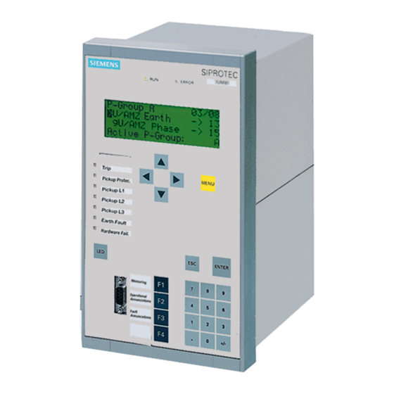
Siemens SIPROTEC 7SJ62 Manual
Multi-functional protective
relay with local control
Hide thumbs
Also See for SIPROTEC 7SJ62:
- Instruction manual (536 pages) ,
- Manual (94 pages) ,
- Technical data manual (58 pages)
Table of Contents

Related Manuals for Siemens SIPROTEC 7SJ62


Summary of Contents for Siemens SIPROTEC 7SJ62
- Page 1 Preface Contents Introduction SIPROTEC Functions Multi-Functional Protective Mounting and Commissioning Relay with Local Control Technical Data 7SJ62/64 Appendix V4.7 Literature Manual Glossary Index C53000-G1140-C207-2...
-
Page 2: C53000-G1140-C207
SIPROTEC, SINAUT, SICAM and DIGSI are registered trademarks Document version V04.01.00 of Siemens AG. Other designations in this manual might be trade- marks whose use by third parties for their own purposes would in- Release date 01.2008 fringe the rights of the owner. -
Page 3: Functions 3
Council Directive 89/336/EEC) and concerning electrical equipment for use within specified voltage limits (Low-voltage Directive 73/23 EEC). This conformity has been established by means of tests conducted by Siemens AG in accor- dance with Article 10 of the Council Directive in agreement with the generic standards EN 61000-6-2 and EN 61000-6-4 for the EMC directive, and with the standard EN 60255-6 for the low-voltage directive. - Page 4 Additional Support Should further information on the System SIPROTEC 4 be desired or should particular problems arise which are not covered sufficiently for the purchaser's purpose, the matter should be referred to the local Siemens rep- resentative. Our Customer Support Center provides a 24-hour service.
- Page 5 Preface Safety Information This manual does not constitute a complete index of all required safety measures for operation of the equip- ment (module, device), as special operational conditions may require additional measures. However, it com- prises important information that should be noted for purposes of personal safety as well as avoiding material damage.
- Page 6 The operational equipment (device, module) may only be used for such applications as set out in the catalogue and the technical description, and only in combination with third-party equipment recommended or approved by Siemens. The successful and safe operation of the device is dependent on proper handling, storage, installation, opera- tion, and maintenance.
- Page 7 Preface Typographic and Symbol Conventions The following text formats are used when literal information from the device or to the device appear in the text flow: Parameter Names Designators of configuration or function parameters which may appear word-for-word in the display of the device or on the screen of a personal computer (with operation software DIGSI), are marked in bold letters in monospace type style.
- Page 8 Preface Besides these, graphical symbols are used in accordance with IEC 60617-12 and IEC 60617-13 or similar. Some of the most frequently used are listed below: Input signal of analog quantity AND-gate operation of input values OR-gate operation of input values Exklusive OR-gate (antivalence): output is active, if only one of the inputs is active Coincidence gate (equivalence): output is active, if both inputs are...
-
Page 9: Table Of Contents
Contents Introduction................19 Overall Operation. - Page 10 Contents Overcurrent Protection 50, 51, 50N, 51N ..........63 2.2.1 General .
- Page 11 Contents Voltage Protection 27, 59............140 2.6.1 Measurement Principle .
- Page 12 Contents 2.11 Monitoring Functions............. . 197 2.11.1 Measurement Supervision.
- Page 13 Contents 2.16 Breaker Failure Protection 50BF ........... . .278 2.16.1 Description .
- Page 14 Contents 2.23 Auxiliary Functions ............. . . 336 2.23.1 Message Processing .
- Page 15 Contents 2.25 Breaker Control ..............378 2.25.1 Control Device .
- Page 16 Contents Final Preparation of the Device............463 Technical Data .
- Page 17 Contents 4.27 Dimensions ..............538 4.27.1 Panel Fush and Cubicle Mounting (Housing Size .
- Page 18 Contents Default Settings..............615 A.5.1 LEDs .
-
Page 19: Introduction
Introduction The device family SIPROTEC 7SJ62/64 devices is introduced in this section. An overview of the devices is pre- sented in their application, characteristics, and scope of functions. Overall Operation Application Scope Characteristics SIPROTEC, 7SJ62/64, Manual C53000-G1140-C207-2, Release date 01.2008... -
Page 20: Overall Operation
1.1 Overall Operation Overall Operation The digital SIPROTEC 7SJ62/64 multifunction protection devices are equipped with a powerful microproces- sor. It allows all tasks to be processed digitally, from the acquisition of measured quantities to sending com- mands to circuit breakers. Figures 1-1 and 1-2 illustrate the basic structure of the 7SJ62 and 7SJ64 and the following paragraphs describe each major element. - Page 21 Introduction 1.1 Overall Operation The 4 voltage transformers of the 7SJ623, 7SJ624 and 7SJ64 can either be applied for the input of 3 phase- to-ground voltages, one displacement voltage V or a further voltage for the synchronizing function. delta The analog input quantities are passed on to the input amplifiers (IA). The input amplifier IA element provides a high-resistance termination for the input quantities.
- Page 22 Introduction 1.1 Overall Operation Microcomputer System Apart from processing the measured values, the microcomputer system (µC) also executes the actual protec- tion and control functions. They especially include: • Filtering and preparation of the measured quantities • Continuous monitoring of the measured quantities •...
- Page 23 Introduction 1.1 Overall Operation Serial Interfaces The Front PC Interface is provided for local communications with a personal computer using the DIGSI soft- ware. This facilitates a comfortable handling of all device functions. The Rear Service Interface can also be used to communicate with the relay from a PC running the DIGSI soft- ware.
-
Page 24: Application Scope
Introduction 1.2 Application Scope Application Scope The digital SIPROTEC 4 7SJ62/64 multifunction protection relays are versatile devices designed for protection, control and monitoring of busbar feeders. The devices can be used for line protection in networks that are grounded, low-resistance grounded, ungrounded, or of a compensated neutral point structure. They are suited for networks that are radial or looped, and for lines with single or multi-terminal feeds. - Page 25 Introduction 1.2 Application Scope The capability of switching primary equipment can be restricted by a setting associated with switching authority (Remote or Local), and by the operating mode (interlocked/non-interlocked, with or without password request). Processing of interlocking conditions for switching (e.g. switchgear interlocking) can be established with the aid of integrated, user-configurable logic functions.
-
Page 26: Characteristics
Introduction 1.3 Characteristics Characteristics General Characteristics • Powerful 32-bit microprocessor system. • Complete digital processing and control of measured values, from the sampling of the analog input quanti- ties to the initiation of outputs, for example, tripping or closing circuit breakers or other switchgear devices. •... - Page 27 Introduction 1.3 Characteristics Ground Fault Protection 50N, 51N • Three definite time overcurrent protective elements and one inverse time overcurrent protective element for high-resistance ground faults in grounded systems; • Different curves of common standards are available for 51 and 51N, or a user-defined characteristic; •...
- Page 28 Introduction 1.3 Characteristics Negative Sequence Protection 46 • Evaluation of negative sequence component of the currents; • Two definite-time elements 46-1 and 46-2 and one inverse-time element 46-TOC; curves of common stan- dards are available for 46-TOC. Motor Starting Protection 48 •...
- Page 29 Introduction 1.3 Characteristics Monitoring Functions • Availability of the device is greatly increased because of self-monitoring of the internal measurement circuits, power supply, hardware, and software; • Current transformer and voltage transformer secondary circuits are monitored using summation and sym- metry check techniques •...
- Page 30 Introduction 1.3 Characteristics Fault Location • Initiation by trip command, external command or dropout of pickup; • Fault distance is calculated and the fault location given in ohms (primary and secondary) and in kilometers or miles; • up to three line sections can be configured. Breaker Failure Protection 50 BF •...
- Page 31 Introduction 1.3 Characteristics Phase Rotation • Selectable ABC or ACB by setting (static) or binary input (dynamic). Circuit-Breaker Maintenance • Statistical methods to help adjust maintenance intervals for CB contacts according to their actual wear; • several independent subfunctions have been implemented (ΣI -procedure, ΣI -procedure, 2P-procedure and I t-procedure);...
- Page 32 Introduction 1.3 Characteristics SIPROTEC, 7SJ62/64, Manual C53000-G1140-C207-2, Release date 01.2008...
-
Page 33: Functions
Functions This chapter describes the numerous functions available on the SIPROTEC 4 device 7SJ62/64. It shows the setting possibilities for each function in maximum configuration. Information with regard to the determination of setting values as well as formulas, if required, are also provided. Based on the following information, it can also be determined which of the provided functions should be used. -
Page 34: General
Functions 2.1 General General The settings associated with the various device functions may be modified using the operating or service inter- face in DIGSI in conjunction with a personal computer. Some parameters may also be changed using the con- trols on the front panel of the device. The procedure is set out in detail in the SIPROTEC System Description /1/. 2.1.1 Functional Scope The 7SJ62/64 relay contains protection functions as well as auxiliary functions. -
Page 35: Setting Notes
Functions 2.1 General 2.1.1.2 Setting Notes Setting the Functional Scope Configuration settings can be entered using a PC and the software program DIGSI and transferred via the front serial port or the rear service interface of the device. The operation via DIGSI is explained in the SIPROTEC 4 System Description. - Page 36 Functions 2.1 General Up to four function groups are available for the synchronization function (only one for 7SJ62). The parameters 161 25 Function 1 to 164 25 Function 4 indicate whether a synchronization function is Disabled or Enabled. The latter is determined by selecting the operating mode ASYN/SYNCHRON (closing takes place for asynchronous and synchronous conditions) or SYNCHROCHECK (corresponds to the classical synchrocheck function).
-
Page 37: Settings
Functions 2.1 General 2.1.1.3 Settings Addr. Parameter Setting Options Default Setting Comments Grp Chge OPTION Disabled Disabled Setting Group Change Option Enabled OSC. FAULT REC. Disabled Enabled Oscillographic Fault Records Enabled Charac. Phase Disabled Definite Time 50/51 Definite Time TOC IEC TOC ANSI User Defined PU User def. - Page 38 Functions 2.1 General Addr. Parameter Setting Options Default Setting Comments Disabled Disabled 49 Thermal Overload Protection No ambient temp With amb. temp. 66 #of Starts Disabled Disabled 66 Startup Counter for Motors Enabled LOAD JAM PROT. Disabled Disabled Load Jam Protection Enabled 27/59 Disabled...
- Page 39 Functions 2.1 General Addr. Parameter Setting Options Default Setting Comments RTD CONNECTION 6 RTD simplex 6 RTD simplex Ext. Temperature Input 6 RTD HDX Connection Type 12 RTD HDX FLEXIBLE FUNC. 1...20 Flex.Function 01 Please select Flexible Functions Flex.Function 02 Flex.Function 03 Flex.Function 04 Flex.Function 05...
-
Page 40: Device, General Settings
Functions 2.1 General 2.1.2 Device, General Settings The device requires some general information. This may be, for example, the type of annunciation to be issued in the event of a power system fault occurs. 2.1.2.1 Description Command-dependent Messages "No Trip – No Flag" The indication of messages masked to local LEDs and the provision of spontaneous messages can be made dependent on whether the device has issued a trip signal. -
Page 41: Settings
Functions 2.1 General Default Display Selection In devices with 4-line displays and depending on the device version, a number of predefined image pages are available. The start page of the default display appearing after startup of the device can be selected in the device data via parameter 640 Start image DD. - Page 42 Functions 2.1 General Information Type of In- Comments formation Resume Resume Clock SyncError Clock Synchronization Error DayLightSavTime Daylight Saving Time Settings Calc. Setting calculation is running Settings Check Settings Check Level-2 change Level-2 change Local change Local setting change Event Lost OUT_Ev Event lost Flag Lost...
-
Page 43: Power System Data 1
Functions 2.1 General 2.1.3 Power System Data 1 2.1.3.1 Description The device requires certain basic data regarding the protected equipment so that the device can adapt to its desired application. These may be, for instance, nominal power system and transformer data, measured quan- tity polarities and their physical connections, breaker properties (where applicable) etc. - Page 44 Functions 2.1 General Polarity of Current Transformers (Power System) At address 201 CT Starpoint, the polarity of the wye-connected current transformers is specified (the fol- lowing figure applies accordingly to two current transformers). This setting determines the measuring direction of the device (forward = line direction). Changing this parameter also results in a polarity reversal of the ground current inputs I or I Figure 2-2...
- Page 45 Functions 2.1 General Current Connection (Power System) Via parameter 251 CT Connect. a special connection of the current transformers can be determined. The standard connection is A, B, C, (Gnd). It may only be changed if the device is set to measure one or more ground currents via two current inputs.
- Page 46 Functions 2.1 General The assignment of the protection functions to the ground current inputs in special connections is set out in the following table. Current input Function Time overcurrent protection ground (Section 2.2) Directional time overcurrent protection ground (Section 2.3) Important! The function „Directional time overcurrent protection ground“...
- Page 47 Functions 2.1 General Distance Unit (Power System) Address 215 Distance Unit allows you to specify the distance unit (km or Miles) for the fault locator. In the absence of a fault locator or if this function has been removed, this parameter is of no importance. Changing the distance unit does not imply an automatic conversion of the setting values that are dependant on the dis- tance unit.
-
Page 48: Motor Starting Protection
Functions 2.1 General Transformation Ratio of Voltage Transformers (VTs) Address 206 Vph / Vdelta informs the device of the adjustment factor between the phase voltage and the displacement voltage. This information is relevant for the processing of ground faults (in grounded systems and ungrounded systems), for the operational measured value VN and measured-variable monitoring. - Page 49 Functions 2.1 General Circuit-breaker Maintenance (Breaker) Parameters 260 to 267 are assigned to CB maintenance. The parameters and the different procedures are explained in the setting notes of this function (see Section 2.23.2). Two-phase Time Overcurrent Protection (Protection Operating Quantities) The two-phase overcurrent protection functionality is used in grounded or compensated systems where inter- action of three-phase devices with existing two-phase protection equipment is required.
-
Page 50: Settings
Functions 2.1 General 2.1.3.3 Settings Addresses which have an appended "A" can only be changed with DIGSI, under "Display Additional Settings". The table indicates region-specific default settings. Column C (configuration) indicates the corresponding sec- ondary nominal current of the current transformer. Addr. -
Page 51: Information List
Functions 2.1 General Addr. Parameter Setting Options Default Setting Comments 250A 50/51 2-ph prot 50, 51 Time Overcurrent with 2ph. prot. 251A CT Connect. A, B, C, (Gnd) A, B, C, (Gnd) CT Connection A,G2,C,G; G->B A,G2,C,G; G2->B Ir-52 10 .. 50000 A 125 A Rated Normal Current (52 Breaker) -
Page 52: Oscillographic Fault Records
Functions 2.1 General 2.1.4 Oscillographic Fault Records The Multi-Functional Protection with Control 7SJ62/64 is equipped with a fault record memory. The instanta- neous values of the measured quantities or i and v or 3 · v and v (only 7SJ623/624 and 7SJ64) (voltages in accordance with connection) are sampled at intervals of 1.25 ms (at 50Hz) and stored in a revolving buffer (16 samples per cycle). -
Page 53: Setting Notes
Functions 2.1 General 2.1.4.2 Setting Notes Configuration Fault recording (waveform capture) will only take place if address 104 OSC. FAULT REC. is set to Enabled. Other settings pertaining to fault recording (waveform capture) are found in the Osc. Fault Rec. OSC. FAULT REC. -
Page 54: Information List
Functions 2.1 General 2.1.4.4 Information List Information Type of In- Comments formation FltRecSta IntSP Fault Recording Start >Trig.Wave.Cap. >Trigger Waveform Capture Wave. deleted OUT_Ev Waveform data deleted 30053 Fault rec. run. Fault recording is running 2.1.5 Settings Groups Up to four different setting groups can be created for establishing the device's function settings. Applications •... -
Page 55: Settings
Functions 2.1 General 2.1.5.3 Settings Addr. Parameter Setting Options Default Setting Comments CHANGE Group A Group A Change to Another Setting Group Group B Group C Group D Binary Input Protocol 2.1.5.4 Information List Information Type of In- Comments formation GroupA act IntSP Setting Group A is active... -
Page 56: Setting Notes
Functions 2.1 General 2.1.6.2 Setting Notes Definition of Nominal Rated Values At addresses 1101 FullScaleVolt. and 1102 FullScaleCurr., the primary reference voltage (phase- to-phase) and reference current (phase) of the protected equipment is entered (e.g. motors). If these reference sizes match the primary nominal values of the VTs and CTs, they correspond to the settings in address 202 and 204 (Section 2.1.3.2). - Page 57 Functions 2.1 General For ground impedance ratios, the following results: Reactance per Unit Length (only for Fault Location) The setting of the reactance per unit length is only important for the utilization of the line fault location function. The reactance setting enables the protective relay to indicate the fault location in terms of distance. The reactance value X' is entered as a reference value x', i.e.
- Page 58 Functions 2.1 General Calculation example: In the following, the same line as illustrated in the example for ground impedance ratios (above) and additional data on the voltage transformers will be used: Current Transformers 500 A/5 A Voltage Transformers 20 kV / 0.1 kV The secondary reactance per unit length is calculated as follows: Line Angle (only for Fault Location) The setting of the line angle is only important for the utilization of the line fault location function.
- Page 59 Functions 2.1 General Line Length (only for Fault Location) The setting of the line length is only important for the utilization of the line fault location function. The line length is required so that the fault location can be given as a reference value (in %). Furthermore, when using several line sections, the respective length of the individual sections is defined.
-
Page 60: Settings
Functions 2.1 General 2.1.6.3 Settings The table indicates region-specific default settings. Column C (configuration) indicates the corresponding sec- ondary nominal current of the current transformer. Addr. Parameter Setting Options Default Setting Comments 1101 FullScaleVolt. 0.10 .. 800.00 kV 12.00 kV Measurem:FullScaleVolt- age(Equipm.rating) 1102... -
Page 61: Information List
Functions 2.1 General Addr. Parameter Setting Options Default Setting Comments 6015 S2: Line angle 10 .. 89 ° 85 ° S2: Line angle 6016 S2: line length 0.1 .. 650.0 Miles 62.1 Miles S2: line length in miles 6017 S2: Line length 0.1 .. -
Page 62: En100-Module
Functions 2.1 General 2.1.7 EN100-Module 2.1.7.1 Functional Description The EN100-Module enables integration of the 7SJ62/64 in 100-Mbit communication networks in control and automation systems with the protocols according to IEC 61850 standard. This standard permits uniform com- munication of the devices without gateways and protocol converters. Even when installed in heterogeneous environments, SIPROTEC 4 relays therefore provide for open and interoperable operation. -
Page 63: Overcurrent Protection 50, 51, 50N, 51N
Functions 2.2 Overcurrent Protection 50, 51, 50N, 51N Overcurrent Protection 50, 51, 50N, 51N Overcurrent protection is the main protection function of the 7SJ62/64 relay. Each phase current and the ground current is provided with four elements. All elements are independent from each other and can be com- bined as desired. -
Page 64: Definite Time, High-Set Elements 50-3, 50-2, 50N-3, 50N-2
Functions 2.2 Overcurrent Protection 50, 51, 50N, 51N The following table gives an overview of the interconnection to other functions of 7SJ62/64. Table 2-1 Interconnection to other functions Overcurrent Ele- Connection to Manual Dynamic Inrush Restraint ments CLOSE Automatic Reclosing Cold Load Pickup 50-1 •... - Page 65 Functions 2.2 Overcurrent Protection 50, 51, 50N, 51N Figure 2-4 Logic diagram for 50-2 for phases If parameter MANUAL CLOSE is set to 50-2 instant. or 50-3 instant. and manual close detection is used, a pickup causes instantaneous tripping, even if the element is blocked via binary input. The same applies to 79AR 50-2 inst.
- Page 66 Functions 2.2 Overcurrent Protection 50, 51, 50N, 51N Figure 2-5 Logic diagram for 50N-2 high-set element If parameter MANUAL CLOSE is set to 50N-2 instant. or 50N-3 instant. and manual close detection is used, a pickup causes instantaneous tripping, even if the element is blocked via binary input. The same applies to AR 50N-2 inst.
-
Page 67: Definite Time Overcurrent Elements 50-1, 50N-1
Functions 2.2 Overcurrent Protection 50, 51, 50N, 51N 2.2.3 Definite Time Overcurrent Elements 50-1, 50N-1 For each element an individual pickup value 50-1 PICKUP or 50N-1 PICKUP is set. Apart from Fundamental, the True RMS can also be measured. Each phase and ground current is compared separately with the setting value 50-1 or 50N-1 for each element. - Page 68 Functions 2.2 Overcurrent Protection 50, 51, 50N, 51N Figure 2-6 Logic diagram for the 50-1 current element for phases The dropout delay only operates if no inrush was detected. An incoming inrush will reset a running dropout delay time. If parameter MANUAL CLOSE is set to 50 -1 instant. and manual close detection is used, a pickup causes instantaneous tripping, even if blocking of the element via binary input is present.
- Page 69 Functions 2.2 Overcurrent Protection 50, 51, 50N, 51N Figure 2-8 Logic diagram for the 50N-1 current element If parameter MANUAL CLOSE is set to 50N-1 instant. and manual close detection applies, the trip is initiated as soon as the pickup conditions arrive, even if the element is blocked via a binary input. The same applies to 79 AR 50N-1 inst.
-
Page 70: Inverse Time Overcurrent Elements 51, 51N
Functions 2.2 Overcurrent Protection 50, 51, 50N, 51N 2.2.4 Inverse Time Overcurrent Elements 51, 51N Inverse time elements are dependent on the variant ordered. They operate with an inverse time characteristic either according to the IEC- or the ANSI-standard or with a user-defined characteristic. The characteristics and associated formulas are given in the Technical Data. - Page 71 Functions 2.2 Overcurrent Protection 50, 51, 50N, 51N Figure 2-10 Logic diagram of the inverse-time overcurrent protection element for phases If parameter MANUAL CLOSE is set to 51 instant. and manual close detection applies, the trip is initiated as soon as the pickup conditions arrive, even if the element is blocked via a binary input. The same applies to 79AR 51 inst.
- Page 72 Functions 2.2 Overcurrent Protection 50, 51, 50N, 51N Figure 2-11 Logic diagram of the inverse-time overcurrent protection element for ground If parameter MANUAL CLOSE is set to 51N instant. and manual close detection applies, the trip is initiated as soon as the pickup conditions arrive, even if the element is blocked via binary input. The same applies to 79AR 51N instantaneous.
-
Page 73: Inverse Time Overcurrent Protection 51V (Voltage-Controlled / Voltage-Restraint)
Functions 2.2 Overcurrent Protection 50, 51, 50N, 51N User-defined Characteristics When user-defined characteristic are used, the tripping curve may be defined point by point. Up to 20 value pairs (current, time) may be entered. The device then approximates the characteristic, using linear interpola- tion. - Page 74 Functions 2.2 Overcurrent Protection 50, 51, 50N, 51N Switching to the lower pickup value or decreasing the pickup threshold is carried out phase-selectively. The assignment of voltages to current-carrying phases is shown in the following table. Table 2-2 Controlling voltages in relation to the fault currents Current Voltage –...
- Page 75 Functions 2.2 Overcurrent Protection 50, 51, 50N, 51N Figure 2-13 Logic diagram of the voltage-controlled inverse time overcurrent protection SIPROTEC, 7SJ62/64, Manual C53000-G1140-C207-2, Release date 01.2008...
- Page 76 Functions 2.2 Overcurrent Protection 50, 51, 50N, 51N Figure 2-14 Logic diagram of the voltage-restraint inverse-time overcurrent protection SIPROTEC, 7SJ62/64, Manual C53000-G1140-C207-2, Release date 01.2008...
-
Page 77: Dynamic Cold Load Pickup Function
Functions 2.2 Overcurrent Protection 50, 51, 50N, 51N 2.2.6 Dynamic Cold Load Pickup Function It may be necessary to dynamically increase the pickup values if, during starting, certain elements of the system show an increased power consumption after a long period of zero voltage (e.g. air-conditioning systems, heating installations, motors). - Page 78 Functions 2.2 Overcurrent Protection 50, 51, 50N, 51N Cross Blocking Since inrush restraint operates individually for each phase, protection is ideal where a power transformer is en- ergized into a single-phase fault and inrush currents are detected on a different healthy phase. However, the protection feature can be configured to allow that not only this phase element but also the remaining elements (including ground) are blocked (the so-called CROSS BLOCK function, address 2203) if the permissible har- monic component of the current is exceeded for only one phase.
- Page 79 Functions 2.2 Overcurrent Protection 50, 51, 50N, 51N Figure 2-15 Logic diagram for inrush restraint SIPROTEC, 7SJ62/64, Manual C53000-G1140-C207-2, Release date 01.2008...
-
Page 80: Pickup Logic And Tripping Logic
Functions 2.2 Overcurrent Protection 50, 51, 50N, 51N 2.2.8 Pickup Logic and Tripping Logic The pickup annunciations of the individual phases (or ground) and the individual elements are combined with each other in such a way that the phase information and the element that has picked up are issued. Table 2-3 Pickup annunciations of the overcurrent protection Internal Annunciation... -
Page 81: Two-Phase Overcurrent Protection (Only Non-Directional)
Functions 2.2 Overcurrent Protection 50, 51, 50N, 51N 2.2.9 Two-phase Overcurrent Protection (Only Non-directional) The two-phase overcurrent protection functionality is used in grounded or compensated systems where inter- action with existing two-phase protection equipment is required. As an isolated or resonant-grounded system remains operational with a single-phase ground fault, this protection serves the purpose of detecting double ground faults with high ground fault currents. -
Page 82: Setting Notes
Functions 2.2 Overcurrent Protection 50, 51, 50N, 51N Figure 2-16 Reverse interlocking protection scheme 2.2.11 Setting Notes General When selecting the time overcurrent protection in DIGSI a dialog box appears with several tabs, such as , , , , and in which the individual parameters can be set. Depending on the functional scope specified during config- uration of the protective functions in addresses 112 Charac. - Page 83 Functions 2.2 Overcurrent Protection 50, 51, 50N, 51N Measurement Methods The comparison values to be used for the respective element can be set in the setting sheets for the elements. • Measurement of the fundamental harmonic (standard method): This measurement method processes the sampled values of the current and filters in numerical order the fundamental harmonic so that the higher harmonics or transient peak currents remain largely unconsidered.
- Page 84 Functions 2.2 Overcurrent Protection 50, 51, 50N, 51N The nominal current of the transformer is: = 84 A (High Voltage Side) = 462 A (Low Voltage NomT, 110 NomT, 20 Side) Current Transformer (High Voltage Side) 100 A / 1 A Current Transformer (Low Voltage Side) 500 A / 1 A Due to the following definition...
- Page 85 Functions 2.2 Overcurrent Protection 50, 51, 50N, 51N 50-1 Element (phases) For setting the 50-1 element, it is the maximum anticipated load current that must be considered above all. Pickup due to overload should never occur since in this mode the device operates as fault protection with cor- respondingly short tripping times and not as overload protection.
- Page 86 Functions 2.2 Overcurrent Protection 50, 51, 50N, 51N The corresponding time multiplier for an IEC characteristic is set at address 1208 51 TIME DIAL and in address 1209 51 TIME DIAL for an ANSI characteristic. It must be coordinated with the grading coordination chart of the system.
- Page 87 Functions 2.2 Overcurrent Protection 50, 51, 50N, 51N The following must be observed: • The value pairs should be entered in increasing sequence. If desired, fewer than 20 pairs can be entered. In most cases, about 10 pairs is sufficient to define the characteristic accurately. A value pair which is not used has to be made invalid by entering "∞”...
- Page 88 Functions 2.2 Overcurrent Protection 50, 51, 50N, 51N The value pairs are entered at address 1231 MofPU Res T/Tp or 1331 MofPU Res T/TEp to recreate the reset curve. The following must be observed: • The current values entered should be those from the following Table 2-5, along with the matching times. De- viating values of MofPU are rounded.
- Page 89 Functions 2.2 Overcurrent Protection 50, 51, 50N, 51N Inrush Restraint When applying the protection device to transformers where high inrush currents are to be expected, the 7SJ62/64 can make use of an inrush restraint function for the overcurrent elements 50-1, 51, 50N-1 and 51N as well as the non-directional overcurrent elements.
- Page 90 Functions 2.2 Overcurrent Protection 50, 51, 50N, 51N Note For an interaction between the automatic reclosing function (79 AR) and the control function, an extended CFC logic is necessary. See margin heading „Close command: Directly or via Control“ in the Setting Notes of the automatic reclosing function (Section 2.14.6).
-
Page 91: Settings
Functions 2.2 Overcurrent Protection 50, 51, 50N, 51N 2.2.12 Settings Addresses which have an appended "A" can only be changed with DIGSI, under "Display Additional Settings". The table indicates region-specific default settings. Column C (configuration) indicates the corresponding sec- ondary nominal current of the current transformer. Addr. - Page 92 Functions 2.2 Overcurrent Protection 50, 51, 50N, 51N Addr. Parameter Setting Options Default Setting Comments 1219A 50-3 measurem. Fundamental Fundamental 50-3 measurement of True RMS Instantaneous 1220A 50-2 measurem. Fundamental Fundamental 50-2 measurement of True RMS 1221A 50-1 measurem. Fundamental Fundamental 50-1 measurement of True RMS...
- Page 93 Functions 2.2 Overcurrent Protection 50, 51, 50N, 51N Addr. Parameter Setting Options Default Setting Comments 1313A MANUAL CLOSE 50N-3 instant. 50N-2 instant. Manual Close Mode 50N-2 instant. 50N-1 instant. 51N instant. Inactive 1314A 50N-2 active Always Always 50N-2 active With 79 Active 1315A 50N T DROP-OUT 0.00 ..
-
Page 94: Information List
Functions 2.2 Overcurrent Protection 50, 51, 50N, 51N 2.2.13 Information List Information Type of In- Comments formation 1704 >BLK 50/51 >BLOCK 50/51 1714 >BLK 50N/51N >BLOCK 50N/51N 1718 >BLOCK 50-3 >BLOCK 50-3 1719 >BLOCK 50N-3 >BLOCK 50N-3 1721 >BLOCK 50-2 >BLOCK 50-2 1722 >BLOCK 50-1... - Page 95 Functions 2.2 Overcurrent Protection 50, 51, 50N, 51N Information Type of In- Comments formation 1838 51N TimeOut 51N Time Out 1839 51N TRIP 51N TRIP 1840 PhA InrushDet Phase A inrush detection 1841 PhB InrushDet Phase B inrush detection 1842 PhC InrushDet Phase C inrush detection 1843...
-
Page 96: Directional Overcurrent Protection 67, 67N
Functions 2.3 Directional Overcurrent Protection 67, 67N Directional Overcurrent Protection 67, 67N With directional overcurrent protection the phase current and the ground currents are each provided with three elements. All elements may be configured independently from each other and combined as desired. High-set current elements 67-2 and overcurrent element 67-1 always operate with a definite tripping time, the third element 67-TOC operates with an inverse tripping time. - Page 97 Functions 2.3 Directional Overcurrent Protection 67, 67N For line sections supplied from two sources or in ring-operated lines, the overcurrent protection has to be sup- plemented by the directional criterion. Figure 2-21 shows a ring system where both energy sources are merged to one single source.
-
Page 98: Definite Time, Directional High-Set Elements 67-2, 67N-2
Functions 2.3 Directional Overcurrent Protection 67, 67N The following table provides an overview of the interconnection to other functions of 7SJ62/64. Table 2-6 Interconnection to other functions Directional Time Connection to Auto- Manual Dynamic Cold Load Inrush Restraint Overcurrent Protec- matic Reclosing CLOSE Pickup... - Page 99 Functions 2.3 Directional Overcurrent Protection 67, 67N Figure 2-22 Logic diagram for directional high-set element 67-2 for phases If parameter MANUAL CLOSE is set to 67-2 instant. and manual close detection applies, the pickup is tripped instantaneously, also if the element is blocked via binary input. The same applies to 79 AR 67-2 inst. SIPROTEC, 7SJ62/64, Manual C53000-G1140-C207-2, Release date 01.2008...
-
Page 100: Definite Time, Directional Overcurrent Elements 67-1, 67N-1
Functions 2.3 Directional Overcurrent Protection 67, 67N 2.3.3 Definite Time, Directional Overcurrent Elements 67-1, 67N-1 For each element an individual pickup value 67-1 PICKUP or 67N-1 PICKUP is set, which can be measured as Fundamental or True RMS. Phase and ground currents are compared separately with the common setting value 67-1 PICKUP or 67N-1 PICKUP. - Page 101 Functions 2.3 Directional Overcurrent Protection 67, 67N Figure 2-23 Logic diagram for the directional relay element 67-1 for phases The dropout delay does only function if no inrush was detected. An approaching inrush resets an already running dropout time delay. SIPROTEC, 7SJ62/64, Manual C53000-G1140-C207-2, Release date 01.2008...
-
Page 102: Inverse Time, Directional Overcurrent Elements 67-Toc, 67N-Toc
Functions 2.3 Directional Overcurrent Protection 67, 67N Figure 2-24 Logic of the dropout delay for 67-1 2.3.4 Inverse Time, Directional Overcurrent Elements 67-TOC, 67N-TOC Inverse time elements are dependent on the variant ordered. They operate either according to the IEC- or the ANSI-standard or to a user-defined characteristic. - Page 103 Functions 2.3 Directional Overcurrent Protection 67, 67N User-defined Characteristics When user-defined characteristic are utilized, the tripping curve may be defined point by point. Up to 20 value pairs (current, time) may be entered. The device then approximates the characteristic, using linear interpola- tion.
-
Page 104: Interaction With Fuse Failure Monitor (Ffm)
Functions 2.3 Directional Overcurrent Protection 67, 67N 2.3.5 Interaction with Fuse Failure Monitor (FFM) Spurious tripping can be caused by failure of a measuring voltage due to short-circuit, broken wire in the voltage transformer's secondary system or pickup of the voltage transformer fuse. Failure of the measuring voltage in one or two poles can be detected, and the directional time overcurrent elements (Dir Phase and Dir Ground) can be blocked (see logic diagrams). - Page 105 Functions 2.3 Directional Overcurrent Protection 67, 67N Direction Determination with Zero-sequence System or Ground Quantities For the directional ground fault elements, direction can be determined by comparing the zero-sequence system quantities. In the current path, the I current is valid, when the transformer neutral current is connected to the device.
- Page 106 Functions 2.3 Directional Overcurrent Protection 67, 67N Table 2-7 Voltage and Current Values for the Determination of Fault Direction in a Phase Element Pickup Selected current Allocated voltage A, B with I >I A, B with I A, B with I <I B, C with I >I...
- Page 107 Functions 2.3 Directional Overcurrent Protection 67, 67N The rotated reference voltage defines the forward and reverse area, see Figure 2-28. The forward area is a range of ±86° around the rotated reference voltage V If the vector of the fault current is in this area, the ref,rot device detects forward direction.
-
Page 108: Reverse Interlocking For Double End Fed Lines
Functions 2.3 Directional Overcurrent Protection 67, 67N Direction Determination of Directional Ground Element with Negative Sequence Values Figure 2-30 shows the treatment of the reference voltage for the directional ground element using the negative sequence values based on a single-pole ground fault in Phase A. As reference voltage, the negative sequence system voltage is used, as current for the direction determination, the negative sequence system current, in which the fault current is displayed. - Page 109 Functions 2.3 Directional Overcurrent Protection 67, 67N During a busbar fault, the device that detects faults in reverse (busbar) direction using the directional relay element 67-1 will block one of the non-directional overcurrent elements (50-1, 50-TOC) of devices at the oppo- site end of the same feeder.
-
Page 110: Setting Notes
Functions 2.3 Directional Overcurrent Protection 67, 67N 2.3.10 Setting Notes General When selecting the directional time overcurrent protection in DIGSI, a dialog box appears with several tabs for setting the associated parameters. Depending on the functional scope specified during configuration of the pro- tective functions in addresses 115 67/67-TOC and 116 67N/67N-TOC, the number of tabs can vary. - Page 111 Functions 2.3 Directional Overcurrent Protection 67, 67N Direction Characteristic The direction characteristic, i.e. the position of the ranges „forward“ and „reverse“ is set for the phase directional elements under address 1519 ROTATION ANGLE and for the ground directional element under address 1619 ROTATION ANGLE.
- Page 112 Functions 2.3 Directional Overcurrent Protection 67, 67N Before Version V4.60, the direction characteristic could only be set in three discrete positions. The settings that correspond with the old parameters 1515 and 1615 are specified as follows. Up to V4.60 As of V4.60 Addr.
- Page 113 Functions 2.3 Directional Overcurrent Protection 67, 67N 67-1 Directional Overcurrent Element (phases) The pickup value of the 67-1 element (67-1 PICKUP) address1504 should be set above the maximum antic- ipated load current. Pickup due to overload should never occur since in this mode the device operates as fault protection with correspondingly short tripping times and not as overload protection.
- Page 114 Functions 2.3 Directional Overcurrent Protection 67, 67N The corresponding element time multiplication factor for an IEC characteristic is set at address 1508 67 TIME DIAL and in address 1509 67 TIME DIAL for an ANSI characteristic. It must be coordinated with the time grading of the network.
- Page 115 Functions 2.3 Directional Overcurrent Protection 67, 67N The default setting of current values is ∞. They are, therefore, not enabled — and no pickup or tripping of these protective functions will occur. The following must be observed: • The value pairs should be entered in increasing sequence. If desired, fewer than 20 pairs may be entered. In most cases, about 10 pairs is sufficient to define the characteristic accurately.
- Page 116 Functions 2.3 Directional Overcurrent Protection 67, 67N Figure 2-33 Using a user-defined curve Inrush Restraint When applying the protection device to transformers where high inrush currents are to be expected, the 7SJ62/64 can make use of an inrush restraint function for the directional overcurrent elements 67-1, 67-TOC, 67N-1 and 67N-TOC as well as the non-directional overcurrent elements.
- Page 117 Functions 2.3 Directional Overcurrent Protection 67, 67N Internal Control Function The manual closing information must be allocated via CFC (interlocking task-level) using the CMD_Information block, if the internal control function is used. Figure 2-34 Example for the generation of a manual close signal using the internal control function Note For an interaction between the automatic reclosing function (79 AR) and the control function, an extended CFC logic is necessary.
-
Page 118: Settings
Functions 2.3 Directional Overcurrent Protection 67, 67N 2.3.11 Settings Addresses which have an appended "A" can only be changed with DIGSI, under "Display Additional Settings". The table indicates region-specific default settings. Column C (configuration) indicates the corresponding sec- ondary nominal current of the current transformer. Addr. - Page 119 Functions 2.3 Directional Overcurrent Protection 67, 67N Addr. Parameter Setting Options Default Setting Comments 1522A 67-TOC MEASUR. Fundamental Fundamental 67-TOC measurement of True RMS 1.00 .. 20.00 I/Ip; ∞ 1530 0.01 .. 999.00 TD 0.05 .. 0.95 I/Ip; ∞ 1531 MofPU Res T/Tp Multiple of Pickup <->...
-
Page 120: Information List
Functions 2.3 Directional Overcurrent Protection 67, 67N Addr. Parameter Setting Options Default Setting Comments 1621A 67N-1 MEASUREM. Fundamental Fundamental 67N-1 measurement of True RMS 1622A 67N-TOC MEASUR. Fundamental Fundamental 67N-TOC measurement of True RMS 1.00 .. 20.00 I/Ip; ∞ 1630 M.of PU TD Multiples of PU Time-... - Page 121 Functions 2.3 Directional Overcurrent Protection 67, 67N Information Type of In- Comments formation 2665 67-1 TRIP 67-1 TRIP 2668 67N-2 BLOCKED 67N-2 is BLOCKED 2669 67-TOC BLOCKED 67-TOC is BLOCKED 2670 67-TOC pickedup 67-TOC picked up 2674 67-TOC Time Out 67-TOC Time Out 2675 67-TOC TRIP...
-
Page 122: Dynamic Cold Load Pickup
Functions 2.4 Dynamic Cold Load Pickup Dynamic Cold Load Pickup With the cold load pickup function, pickup and delay settings of directional and non-directional time overcurrent protection can be changed over dynamically. Applications • It may be necessary to dynamically increase the pickup values if, during starting and for a short time there- after, certain elements of the system have an increased power consumption after a long period of zero voltage (e.g. - Page 123 Functions 2.4 Dynamic Cold Load Pickup If overcurrent elements are picked up while time Active Time is running, the fault generally prevails until pickup drops out, using the dynamic settings. Only then the parameters are set back to "normal". If the dynamic setting values were activated via the binary input „>ACTIVATE CLP“ or the signal "79M Auto Reclosing ready"...
- Page 124 Functions 2.4 Dynamic Cold Load Pickup Figure 2-36 Logic diagram of the dynamic cold load pickup function (50c, 50Nc, 51c, 51Nc, 67c, 67Nc) SIPROTEC, 7SJ62/64, Manual C53000-G1140-C207-2, Release date 01.2008...
-
Page 125: Setting Notes
Functions 2.4 Dynamic Cold Load Pickup 2.4.2 Setting Notes General The dynamic cold load pickup function can only be enabled if address 117 Coldload Pickup was set to Enabled during configuration of the protective functions. If not required, this function should be set to Disabled. -
Page 126: Settings
Functions 2.4 Dynamic Cold Load Pickup Directional 67/67–TOC Elements (phases) The dynamic pickup values and time delays associated with directional overcurrent phase protection are set at address block 20 The dynamic pickup and delay settings for the 67-2 high-set element are set at addresses 2001 67c-2 PICKUP and 2002 67c-2 DELAY respectively;... - Page 127 Functions 2.4 Dynamic Cold Load Pickup Addr. Parameter Setting Options Default Setting Comments 1.00 .. 35.00 A; ∞ ∞ A 1808 50c-3 PICKUP 50c-3 Pickup 5.00 .. 175.00 A; ∞ ∞ A 0.00 .. 60.00 sec; ∞ 1809 50c-3 DELAY 0.00 sec 50c-3 Time Delay 0.05 ..
-
Page 128: Information List
Functions 2.4 Dynamic Cold Load Pickup 2.4.4 Information List Information Type of In- Comments formation 1730 >BLOCK CLP >BLOCK Cold-Load-Pickup 1731 >BLK CLP stpTim >BLOCK Cold-Load-Pickup stop timer 1732 >ACTIVATE CLP >ACTIVATE Cold-Load-Pickup 1994 CLP OFF Cold-Load-Pickup switched OFF 1995 CLP BLOCKED Cold-Load-Pickup is BLOCKED 1996... -
Page 129: Single-Phase Overcurrent Protection
Functions 2.5 Single-Phase Overcurrent Protection Single-Phase Overcurrent Protection The single-phase overcurrent protection evaluates the current that is measured by the sensitive I - or the normal I input. Which input is used depends on the device version according to the order number. Applications •... - Page 130 Functions 2.5 Single-Phase Overcurrent Protection The following figure shows the logic diagram of the single-phase overcurrent protection function. Figure 2-38 Logic diagram of the single-phase time overcurrent protection SIPROTEC, 7SJ62/64, Manual C53000-G1140-C207-2, Release date 01.2008...
-
Page 131: High-Impedance Ground Fault Unit Protection
Functions 2.5 Single-Phase Overcurrent Protection 2.5.2 High-impedance Ground Fault Unit Protection Application Examples In the high-impedance procedure, all CT's operate at the limits of the protected zone parallel on a common, relatively high-resistive resistor R whose voltage is measured. The CTs must be of the same design and feature at least a separate core for high-impedance protection. In particular, they must have the same transformer ratios and approximately identical knee-point voltage. - Page 132 Functions 2.5 Single-Phase Overcurrent Protection Figure 2-40 Principle of ground fault protection according to the high-impedance principle When a ground fault occurs in the protected zone (Fig. 2-40 right), there is always a starpoint current I . The grounding conditions in the rest of the network determine how strong a zero sequence current from the system is.
-
Page 133: Tank Leakage Protection
Functions 2.5 Single-Phase Overcurrent Protection For protection against overvoltages it is also important that the device is directly connected to the grounded side of the current transformers so that the high voltage at the resistor can be kept away from the device. For generators, motors and shunt reactors high-impedance protection can be used analogously. -
Page 134: Setting Notes
Functions 2.5 Single-Phase Overcurrent Protection 2.5.4 Setting Notes General Single-phase time overcurrent protection can be set ON or OFF at address 2701 50 1Ph. The settings are based on the particular application. The setting ranges depend on whether the current mea- suring input is a sensitive or a normal input transformer (see also „Ordering Information“... - Page 135 Functions 2.5 Single-Phase Overcurrent Protection That means = 5 A (from 800/5) = 10 (from 5P10) = 30 VA The internal burden is often stated in the test report of the current transformer. If not, it can be derived from a DC measurement on the secondary winding.
- Page 136 Functions 2.5 Single-Phase Overcurrent Protection The voltage across R is then · ( 2R It is assumed that the pickup value of the 7SJ62/64 corresponds to half the knee-point voltage of the current transformers. In the balanced case results This results in a stability limit I , i.e.
- Page 137 Functions 2.5 Single-Phase Overcurrent Protection Calculation Example: For the 5 A CT as above desired pickup value I = 0.1 A (equivalent to 16 A primary) For the 1 A CT as above desired pickup value I = 0.05 A (equivalent to 40 A primary) The required short-term power of the resistor is derived from the knee-point voltage and the resistance: As this power only appears during ground faults for a short period of time, the rated power can be smaller by approx.
- Page 138 Functions 2.5 Single-Phase Overcurrent Protection If performance makes it necessary to switch several varistors in parallel, preference should by given to types with a flat characteristic to avoid asymmetrical loading. therefore recommend the following types from METROSIL: 600A/S1/S256 (k = 450, β = 0.25) 600A/S1/S1088 (k = 900, β...
-
Page 139: Settings
Functions 2.5 Single-Phase Overcurrent Protection 2.5.5 Settings The table indicates region-specific default settings. Column C (configuration) indicates the corresponding sec- ondary nominal current of the current transformer. Addr. Parameter Setting Options Default Setting Comments 2701 50 1Ph 50 1Ph 0.05 .. 35.00 A; ∞ 2702 50 1Ph-2 PICKUP 0.50 A... -
Page 140: Voltage Protection 27, 59
Functions 2.6 Voltage Protection 27, 59 Voltage Protection 27, 59 Voltage protection has the task to protect electrical equipment against undervoltage and overvoltage. Both op- erational states are unfavorable as overvoltage may cause for example insulation problems or undervoltage may cause stability problems. There are two elements each available for overvoltage protection and undervoltage protection. - Page 141 Functions 2.6 Voltage Protection 27, 59 Function Connection, single-phase Selectable voltage Threshold to be set as (address 240) Overvoltage Any phase-to-phase or None Phase-to-phase or Undervoltage phase-to-ground voltage (direct evaluation of the voltage connected phase-to-ground voltage (see also Section 2.24) in accordance with address 240) (in accordance with address 240) Current Criterion...
-
Page 142: Overvoltage Protection 59
Functions 2.6 Voltage Protection 27, 59 2.6.2 Overvoltage Protection 59 Function The overvoltage protection has two elements. In case of a high overvoltage, tripping switchoff is performed with a short-time delay, whereas in case of less severe overvoltages, the switchoff is performed with a longer time delay. -
Page 143: Undervoltage Protection 27
Functions 2.6 Voltage Protection 27, 59 2.6.3 Undervoltage Protection 27 Function Undervoltage protection consists of two definite time elements (27-1 PICKUP and 27-2 PICKUP). Therefore, tripping can be time-graded depending on how severe voltage collapses are. Voltage thresholds and time delays can be set individually for both elements. - Page 144 Functions 2.6 Voltage Protection 27, 59 Figure 2-47 Typical fault profile for load side connection of the voltage transformers (with current supervision) Upon the closing of the circuit breaker, current criterion is delayed for a short period of time. If the voltage cri- terion drops out during this time period (about 60 ms), the protection function does not pick up.
- Page 145 Functions 2.6 Voltage Protection 27, 59 The following Figure shows the logic diagram of the undercurrent protection function. Figure 2-48 Logic diagram of the undervoltage protection SIPROTEC, 7SJ62/64, Manual C53000-G1140-C207-2, Release date 01.2008...
-
Page 146: Setting Notes
Functions 2.6 Voltage Protection 27, 59 2.6.4 Setting Notes General Voltage protection is only effective and accessible if address 150 27/59 is set to Enabled during configuration of protection functions. If this function is not required, then Disabled is set. The voltage to be evaluated is selected in Power System Data 1 (see Chapter 2.6, Table 2-11). - Page 147 Functions 2.6 Voltage Protection 27, 59 Overvoltage Protection - Negative Sequence System V2 In a three-phase transformer connection, parameter 614 OP. QUANTITY 59 can determine that the negative sequence system V2 can be evaluated as a measured value for the overvoltage protection. The negative se- quence system detects voltage unbalance and can be used for the stabilization of the time overcurrent protec- tion.
- Page 148 Functions 2.6 Voltage Protection 27, 59 Undervoltage Protection with Phase-to-phase or Phase-to-ground Voltages In parameter 615 OP. QUANTITY 27 you can determine foor undervoltage protection in a three-phase con- nection that instead of the positive-sequence system V1, the smallest of the phase-to-phase voltages Vphph or the smallest phase-to-ground voltage Vph-n is configured as a measured quantity.
-
Page 149: Settings
Functions 2.6 Voltage Protection 27, 59 Current Criterion for Undervoltage Protection The 27-1 element and the 27-2 element can be supervised by the current flow monitoring setting. If the CURRENT SUPERV. is switched ON at address 5120 (factory setting), the release condition of the current cri- terion must be fulfilled in addition to the corresponding undervoltage condition, which means that a configured minimum current (BkrClosed I MIN, address 212) must be present to make sure that this protective function can pick up. -
Page 150: Information List
Functions 2.6 Voltage Protection 27, 59 Addr. Parameter Setting Options Default Setting Comments 5103 27-1 PICKUP 10 .. 120 V 75 V 27-1 Pickup 0.00 .. 100.00 sec; ∞ 5106 27-1 DELAY 1.50 sec 27-1 Time Delay 5110 27-2 PICKUP 10 .. -
Page 151: Negative Sequence Protection 46
Functions 2.7 Negative Sequence Protection 46 Negative Sequence Protection 46 Negative sequence protection detects unbalanced loads on the system. Applications • The application of unbalanced load protection to motors has a special significance. Unbalanced loads create counter-rotating fields in three-phase induction motors, which act on the rotor at double frequency. Eddy cur- rents are induced at the rotor surface, and local overheating in rotor end zones and the slot wedge begins to take place. -
Page 152: Inverse Time Characteristic 46-Toc
Functions 2.7 Negative Sequence Protection 46 Settable Dropout Times Pickup stabilization for the definite-time tripping characteristic 46-1, 46-2 can be accomplished by means of set- table dropout times. This facility is used in power systems with possible intermittent faults. Used together with electromechanical relays, it allows different dropout responses to be adjusted and time grading of digital and electromechanical relays to be implemented. - Page 153 Functions 2.7 Negative Sequence Protection 46 Dropout for IEC Curves The element drops out when the negative sequence current decreases to approx. 95% of the pickup setting. The time delay resets immediately in anticipation of another pickup. Dropout for ANSI Curves When using an ANSI curve, select if dropout after pickup is instantaneous or with disk emulation.
- Page 154 Functions 2.7 Negative Sequence Protection 46 Figure 2-51 Logic diagram of the unbalanced load protection The pickup of the definite time overcurrent protection can be stabilized by the configured dropout time 4012 46 T DROP-OUT. This time is started and maintains the pickup condition if the current falls below the threshold. Therefore, the function does not drop out at high speed.
-
Page 155: Setting Notes
Functions 2.7 Negative Sequence Protection 46 2.7.3 Setting Notes General The function type has been specified during configuration of the protection functions (Section 2.1.1.2, address 140 46). If only the definite time elements are desired, the address 46 should be set to Definite Time. Se- lecting 46 = TOC IEC or TOC ANSI in address 140 will additionally make all parameters available that are relevant for the inverse time curves. - Page 156 Functions 2.7 Negative Sequence Protection 46 Examples: Motor with the following data: Nominal current = 545 A Nom Motor Continuously permissible negative = 0.11 continuous 2 dd prim Nom Motor sequence current Briefly permissible negative se- = 0.55 for T max = 1 s 2 long-term prim Nom Motor quence current...
- Page 157 Functions 2.7 Negative Sequence Protection 46 The following fault currents may be detected at the low side: If 46-1 PICKUP on the high side of the devices is set to = 0.1, then a fault current of I = 3 · TR ·...
-
Page 158: Settings
Functions 2.7 Negative Sequence Protection 46 2.7.4 Settings Addresses which have an appended "A" can only be changed with DIGSI, under "Display Additional Settings". The table indicates region-specific default settings. Column C (configuration) indicates the corresponding sec- ondary nominal current of the current transformer. Addr. -
Page 159: Motor Protection
Functions 2.8 Motor Protection Motor Protection For the protection of motors, devices 7SJ62/64 are provided with a motor starting protection function, a restart inhibit and a load jam protection. The starting protection function protects the motor from prolonged startup pro- cedures thus supplementing the overload protection (see Section 2.10). - Page 160 Functions 2.8 Motor Protection The tripping time is calculated based on the following equation: with Actual tripping time for flowing current I TRIP (address 4103, STARTUP TIME or 4105, Tripping time for nominal startup current I max STARTUP STARTUP STARTUP T WARM) Current actually flowing (measurement value) Nominal startup current of the motor (address 4102, STARTUP CURRENT) STARTUP...
- Page 161 Functions 2.8 Motor Protection Logic Motor starting protection may be switched on or off. In addition, motor starting protection may be blocked via a binary input which will reset timers and pickup annunciations. The following figure illustrates the logic of motor starting protection.
-
Page 162: Setting Notes
Functions 2.8 Motor Protection Switching of Startup Times The motor manufacturer provides startup time curves for both cold and warm motor conditions (see Figure 2- 52). The function Motor Starting Protection automatically performs a switching. The "warm motor" condition is derived from the thermal storage of the restart inhibit (see Section 2.8.2). - Page 163 Functions 2.8 Motor Protection The setting for address STARTUP CURRENT (I ) as a secondary value is calculated as follows: STARTUP For reduced voltage, the startup current is also reduced almost linearly. At 80 % nominal voltage, the startup current in this example is reduced to 0.8 · I = 2.5.
- Page 164 Functions 2.8 Motor Protection Threshold Values "cold" / "warm" Motor Parameter 4106 TEMP.COLD MOTOR determines the threshold value. It is derived from the number of cold ) and warm (n ) motor startups. cold warm Unless specified otherwise, three cold and two warm startups (n = 3;...
-
Page 165: Motor Restart Inhibit 66
Functions 2.8 Motor Protection 2.8.2 Motor Restart Inhibit 66 The motor restart inhibit prevents restarting of the motor when this restart may cause the permissible thermal limits of the rotor to be exceeded. Additionally, the function can trip directly if the rotor temperature exceeds the maximum admissible temperature (100%) (rotor overload). - Page 166 Functions 2.8 Motor Protection Figure 2-54 Temperature curve at the rotor and in the thermal replica during repeated start-up attempts Although the heat distribution on the rotor bars may severely differ during motor starting, the different maximum temperatures in the the rotor are not pertinant for motor restart inhibit (see Figure 2-54). It is much more impor- tant to establish a thermal replica, after a complete motor start, that is appropriate for the protection of the motor's thermal condition.
- Page 167 Functions 2.8 Motor Protection Restart Threshold If the rotor temperature has exceeded the restart threshold, the motor cannot be restarted. The blocking signal is not lifted unless the rotor temperature has fallen below the restarting limit, that is, when exactly one start becomes possible without exceeding the excessive rotor temperature limit.
- Page 168 Functions 2.8 Motor Protection Total Time T Reclose The total waiting time T before the motor can be restarted is therefore composed of the equilibrium time, Reclose the time T calculated from the thermal replica and the value that is needed to drop below the limit for re- Restart starting.
- Page 169 Functions 2.8 Motor Protection Behavior in Case of Power Supply Failure Depending on the setting in address 235 ATEX100 of Power System Data 1 (see Section 2.1.3.2) the value of the thermal replica is either reset to zero (ATEX100 = NO) if the power supply voltage fails, or cyclically buffered in a non-volatile memory (ATEX100 = YES) so that it is maintained in the event of auxiliary supply voltage fail- ure.
- Page 170 Functions 2.8 Motor Protection Figure 2-55 Logic diagram for the restart inhibit SIPROTEC, 7SJ62/64, Manual C53000-G1140-C207-2, Release date 01.2008...
-
Page 171: Setting Notes
Functions 2.8 Motor Protection 2.8.2.2 Setting Notes General Restart inhibit is only effective and accessible if address 143 48 is set to Enabled. If not required, this function is set to Disabled. The function can be turned ON or OFF under address 4301 FCT 66.. Note When function settings of the motor restart inhibit are changed, the thermal replica of this function is reset. - Page 172 Functions 2.8 Motor Protection Example: Motor with the following data: Rated Voltage = 6600 V Nominal current = 126 A Startup current = 624 A STARTUP Startup duration = 8.5 s Start max. Permitted starts with cold motor cold Permitted starts with warm motor warm Current transformer 200 A / 1 A...
- Page 173 Functions 2.8 Motor Protection Temperature Behavior during Changing Operating States For a better understanding of the above considerations several possible operating ranges in two different op- erating areas will be discussed in the following paragraph. Settings indicated above are to be used prevaling 3 cold and 2 warm startup attempts have resulted in the restart limit reaching 66.7%.
- Page 174 Functions 2.8 Motor Protection B) Above the thermal restarting limit: A startup brings the machine from load operation into a temperature range far above the thermal restarting limit and the machine is stopped. The minimum inhibit time and the equilibrium time are started and „66 TRIP“...
-
Page 175: Load Jam Protection (51M)
Functions 2.8 Motor Protection 2.8.3 Load Jam Protection (51M) The load jam protection serves to protect the motor during sudden rotor blocking. Damage to drives, bearings and other mechanic motor components can be avoided or reduced by means of quick motor shutdown. The blocking results in a current jump in the phases. - Page 176 Functions 2.8 Motor Protection Figure 2-59 illustrates an example of a locked rotor caused by mechanical overload. It should be noted that the current flow increases substantially as soon as the mechanical load reaches the stability limit. Figure 2-59 Example of the time characteristic for mechanical rotor blocking Logic A continuous comparison of the motor current with the configured threshold values of the protection function takes place for the purpose of detecting a locked rotor.
- Page 177 Functions 2.8 Motor Protection Figure 2-60 Logic diagram of the load jam protection SIPROTEC, 7SJ62/64, Manual C53000-G1140-C207-2, Release date 01.2008...
-
Page 178: Setting Notes
Functions 2.8 Motor Protection 2.8.3.2 Setting Notes Elements A warning and a tripping element can be configured. The threshold value of the tripping element 4402 Load Jam I> is usually configured below motor startup at double motor ampere rating. Warning element 4404 I Alarm is naturally set below the tripping element, to approx. - Page 179 Functions 2.8 Motor Protection Figure 2-61 Example of a complete motor protection characteristic Example: Motor with the following data: Nominal voltage = 6600 V Nominal current = 126 A Long-term current rating = 135 A Startup duration = 8.5 s startmax.
-
Page 180: Motorprotection (Motor Starting Protection 48, Motor Restart Inhibit 66, Loadjam)
Functions 2.8 Motor Protection 2.8.4 Motorprotection (Motor Starting Protection 48, Motor Restart Inhibit 66, LoadJam) Functions relevant to Motor Protection and Restart Inhibit for Motors and Load Jam Protection are described in the aforegoing two sections and contain information concerning configuration. 2.8.4.1 Settings The table indicates region-specific default settings. -
Page 181: Information List
Functions 2.8 Motor Protection Addr. Parameter Setting Options Default Setting Comments 4401 Load Jam Prot. Load Jam Protection Alarm Only 4402 Load Jam I> 0.50 .. 12.00 A 2.00 A Load Jam Tripping Threshold 2.50 .. 60.00 A 10.00 A 4403 TRIP DELAY 0.00 .. -
Page 182: Frequency Protection 81 O/U
Functions 2.9 Frequency Protection 81 O/U Frequency Protection 81 O/U The frequency protection function detects abnormally high and low frequencies in the system or in electrical machines. If the frequency lies outside the allowable range, appropriate actions are initiated, such as load shedding or separating a generator from the system. - Page 183 Functions 2.9 Frequency Protection 81 O/U The following figure shows the logic diagram for the frequency protection function. Figure 2-62 Logic diagram of the frequency protection SIPROTEC, 7SJ62/64, Manual C53000-G1140-C207-2, Release date 01.2008...
-
Page 184: Setting Notes
Functions 2.9 Frequency Protection 81 O/U 2.9.2 Setting Notes General Frequency protection is only in effect and accessible if address 154 81 O/U is set to Enabled during config- uration of protective functions. If the fuction is not required Disabled is set. The function can be turned ON or OFF under address 5401 FCT 81 O/U. -
Page 185: Settings
Functions 2.9 Frequency Protection 81 O/U 2.9.3 Settings Addresses which have an appended "A" can only be changed with DIGSI, under "Display Additional Settings". Addr. Parameter Setting Options Default Setting Comments 5401 FCT 81 O/U 81 Over/Under Frequency Protec- tion 5402 Vmin 10 .. -
Page 186: Information List
Functions 2.9 Frequency Protection 81 O/U 2.9.4 Information List Information Type of In- Comments formation 5203 >BLOCK 81O/U >BLOCK 81O/U 5206 >BLOCK 81-1 >BLOCK 81-1 5207 >BLOCK 81-2 >BLOCK 81-2 5208 >BLOCK 81-3 >BLOCK 81-3 5209 >BLOCK 81-4 >BLOCK 81-4 5211 81 OFF 81 OFF... -
Page 187: Thermal Overload Protection 49
Functions 2.10 Thermal Overload Protection 49 2.10 Thermal Overload Protection 49 The thermal overload protection is designed to prevent thermal overloads from damaging the protected equip- ment. The protection function represents a thermal replica of the equipment to be protected (overload protec- tion with memory capability). - Page 188 Functions 2.10 Thermal Overload Protection 49 The protection feature therefore represents a thermal replica of the equipment to be protected (overload pro- tection with memory capability). Both the previous history of an overload and the heat loss to the environment are taken into account.
- Page 189 Functions 2.10 Thermal Overload Protection 49 Blocking The thermal memory may be reset via a binary input („>RES 49 Image“) and the current-related overtem- perature value is thus reset to zero. The same is accomplished via the binary input („>BLOCK 49 O/L“); in this case the entire overload protection is blocked completely, including the current warning element.
- Page 190 Functions 2.10 Thermal Overload Protection 49 Figure 2-63 Logic diagram of the overload protection SIPROTEC, 7SJ62/64, Manual C53000-G1140-C207-2, Release date 01.2008...
-
Page 191: Setting Notes
Functions 2.10 Thermal Overload Protection 49 2.10.2 Setting Notes General The overload protection is only in effect and accessible if address 142 49 = No ambient temp or = With amb. temp. during configuration. If the function is not required Disabled is set. Transformers and cable are prone to damage by overloads that last for an extended period of time. - Page 192 Functions 2.10 Thermal Overload Protection 49 For the 49 K-FACTOR to be set in the device the following applies (address 4202) with Permissible thermal primary current of the motor max prim Nominal current of the protected object Nom Obj. Nominal primary CT current Nom CT prim Example: Motor and current transformer with the following data: Permissible Continuous Current...
- Page 193 Functions 2.10 Thermal Overload Protection 49 Example: Cable and current transformer with the following data: = 500 A at Θ Permissible Continuous Current I = 40 °C Maximum Current for 1 s = 45 · I = 22.5 kA Current Transformer 600 A / 1 A Example: Cable and current transformer with the following data: Thus results:...
- Page 194 Functions 2.10 Thermal Overload Protection 49 Ambient or Coolant Temperature The specifications made up to now are sufficient to model the overtemperature. The ambient or coolant tem- perature, however, can also be processed. This has to be communicated to the device as digitalized measured value via the interface.
- Page 195 Functions 2.10 Thermal Overload Protection 49 Example: Machine: I = 483 A Nom Mach at Θ =1.15 I = 40 °C max Mach Θ = 93 °C Temperature at I Nom Mach Nom Mach τ = 600 s (thermal time constant of the machine) Current transformer: 500 A / 1 A Motor Starting Recognition The motor starting is detected when setting I MOTOR START at address 1107 is exceeded.
-
Page 196: Settings
Functions 2.10 Thermal Overload Protection 49 2.10.3 Settings Addresses which have an appended "A" can only be changed with DIGSI, under "Display Additional Settings". The table indicates region-specific default settings. Column C (configuration) indicates the corresponding sec- ondary nominal current of the current transformer. Addr. -
Page 197: Monitoring Functions
Functions 2.11 Monitoring Functions 2.11 Monitoring Functions The device is equipped with extensive monitoring capabilities - both for hardware and software. In addition, the measured values are also constantly monitored for plausibility, therefore, the current transformer and voltage transformer circuits are largely integrated into the monitoring. 2.11.1 Measurement Supervision 2.11.1.1 General... - Page 198 Functions 2.11 Monitoring Functions Measurement Value Acquisition – Currents The monitoring of the device-internal measured-value acquisition of the currents can be effected via the current sum monitoring. Up to four input currents are measured by the device. If the three phase currents and the ground current from the current transformer starpoint are connected with the device, the sum of the four digitized currents must be zero.
- Page 199 Functions 2.11 Monitoring Functions The following logic diagram illustrates the operational mode of the current sum monitoring. Figure 2-65 Logic Diagram of the fast current sum monitoring AD Transformer Monitoring The digitized sampled values are being monitored in respect of their plausibility. If the result is not plausible, message 181 „Error A/D-conv.“...
-
Page 200: Monitoring Of The Hardware Modules
Functions 2.11 Monitoring Functions 2.11.1.3 Monitoring of the Hardware Modules The device is able to recognize location and malfunctions of hardware modules during operation. In the event of a fault, messages „Error Board 1“ (FNo. 183) to „Error Board 7“ (FNo. 189) are initiated. The module number corresponds to the address number (e.g. -
Page 201: Monitoring Of The Transformer Circuits
Functions 2.11 Monitoring Functions 2.11.1.5 Monitoring of the Transformer Circuits Interruptions or short circuits in the secondary circuits of the current and voltage transformers, as well as faults in the connections (important for commissioning!), are detected and reported by the device. The measured quantities are cyclically checked in the background for this purpose, as long as no system fault is present. - Page 202 Functions 2.11 Monitoring Functions | < BAL. FACTOR V as long as | V | > BALANCE V-LIMIT. Where V | / | V is the highest of the the smallest. The symmetry factor BAL. FACTOR V (address 8103) represents the three voltages and V allowable asymmetry of the conductor voltages while the limit value BALANCE V-LIMIT (address 8102) is the lower limit of the operating range of this monitoring (see Figure 2-67).
-
Page 203: Measurement Voltage Failure Detection
Functions 2.11 Monitoring Functions 2.11.1.6 Measurement Voltage Failure Detection Requirements The measurement voltage failure detection function, refered to as „Fuse Failure Monitor“ (FFM), only operates under the following condition: • Three phase-to-ground voltages are connected; with phase-to-phase voltages and V or single-phase con- nection, the function is disabled. - Page 204 Functions 2.11 Monitoring Functions The generation of an internal signal “Alarm FFM isol. N.“ for the mode of operation in an isolated system is illustrated in Figure 2-69. Figure 2-68 Logic diagram of the Fuse Failure Monitor for grounded networks SIPROTEC, 7SJ62/64, Manual C53000-G1140-C207-2, Release date 01.2008...
- Page 205 Functions 2.11 Monitoring Functions Mode of Operation - Isolated System The FFM can also function in isolated and compensated (grounded) systems where only low ground currents are expected. This is indicated to the device via address 5301 FUSE FAIL MON.. The logic diagram on the mode of operation in an isolated system is illustrated in Figure 2-69.
- Page 206 Functions 2.11 Monitoring Functions Single- and Two-pole Faults in Voltage Transformer Circuits The measuring voltage failure detection is based on the fact that a significant negative sequence system is formed in the voltage during a single- or two-pole voltage failure, without influencing the current. This enables a clear distinction from asymmetries impressed by the power system.
-
Page 207: Broken Wire Monitoring Of Voltage Transformer Circuits
Functions 2.11 Monitoring Functions 2.11.1.7 Broken Wire Monitoring of Voltage Transformer Circuits Requirements This function is only available in device version „World“ (Ordering Information Pos. 10 = B), as it is only used in certain regions. Furthermore, the measurement of all three phase-to-ground voltages is a requirement. If only two phase-to-phase voltages were measured, it would not be possible to evaluate two of the required criteria. - Page 208 Functions 2.11 Monitoring Functions The following logic diagram shows how broken wire monitoring functions. Figure 2-70 Logic diagram for broken wire monitoring SIPROTEC, 7SJ62/64, Manual C53000-G1140-C207-2, Release date 01.2008...
-
Page 209: Setting Notes
Functions 2.11 Monitoring Functions 2.11.1.8 Setting Notes Measured Value Monitoring The sensitivity of measured value monitor can be modified. Default values which are sufficient in most cases are preset. If especially high operating asymmetries in the currents and/or voltages are to be expected during operation, or if it becomes apparent during operation that certain monitoring functions activate sporadically, then the setting should be less sensitive. -
Page 210: Settings
Functions 2.11 Monitoring Functions Note The setting under address 5310 BLOCK PROT. has no effect on the flexible protection functions. A separate blocking can be selected for that purpose. The function may be disabled in address 5301 FUSE FAIL MON., e.g. when performing asymmetrical tests. 2.11.1.9 Settings The table indicates region-specific default settings. -
Page 211: Information List
Functions 2.11 Monitoring Functions Addr. Parameter Setting Options Default Setting Comments Σ I THRESHOLD 0.05 .. 2.00 A; ∞ 8106 0.10 A Summated Current Moni- toring Threshold 0.25 .. 10.00 A; ∞ 0.50 A Σ I FACTOR 8107 0.00 .. 0.95 0.10 Summated Current Moni- toring Factor... -
Page 212: Trip Circuit Supervision 74Tc
Functions 2.11 Monitoring Functions 2.11.2 Trip Circuit Supervision 74TC Devices 7SJ62/64 are equipped with an integrated trip circuit supervision. Depending on the number of avail- able binary inputs (not connected to a common potential), supervision with one or two binary inputs can be se- lected. - Page 213 Functions 2.11 Monitoring Functions Supervision with two binary inputs not only detects interruptions in the trip circuit and loss of control voltage, it also supervises the response of the circuit breaker using the position of the circuit breaker auxiliary contacts. Depending on the conditions of the trip contact and the circuit breaker, the binary inputs are activated (logical condition "H"...
- Page 214 Functions 2.11 Monitoring Functions Supervision with One Binary Input The binary input is connected according to the following figure in parallel with the associated trip contact of the protection relay. The circuit breaker auxiliary contact is bridged with a bypass resistor R. Figure 2-73 Trip circuit supervision with one binary input During normal operation, the binary input is activated (logical condition "H") when the trip contact is open and...
-
Page 215: Setting Notes
Functions 2.11 Monitoring Functions The following figure shows the logic diagram for the message that can be generated by the trip circuit monitor, depending on the control settings and binary inputs. Figure 2-75 Message logic for trip circuit supervision 2.11.2.2 Setting Notes General The function is only effective and accessible if address 182 (Section 2.1.1.2) was set to either 2 Binary Inputs or 1 Binary Input during configuration, the appropriate number of binary inputs has been config-... -
Page 216: Settings
Functions 2.11 Monitoring Functions 2.11.2.3 Settings Addr. Parameter Setting Options Default Setting Comments 8201 FCT 74TC 74TC TRIP Circuit Supervision 8202 Alarm Delay 1 .. 30 sec 2 sec Delay Time for alarm 2.11.2.4 Information List Information Type of In- Comments formation 6851... - Page 217 Functions 2.11 Monitoring Functions Table 2-14 Summary of malfunction responses by the protection relay Monitoring Possible Cause Malfunction Re- Message (No.) Output sponse AC/DC supply voltage loss External Device shutdown All LEDs dark drops out (Nominal voltage) in- ternal (power supply) Internal supply voltages Internal (power Device shutdown...
- Page 218 Functions 2.11 Monitoring Functions Monitoring Possible Cause Malfunction Re- Message (No.) Output sponse Fuse Failure Monitor External Message „VT FuseFail>10s“ As allocated (voltage transformer) (169) „VT FuseFail“ (170) Trip circuit monitoring External (trip circuit or Message „74TC Trip cir.“ (6865) As allocated control voltage) Secondary voltage transform-...
-
Page 219: Ground Fault Protection 64, 67N(S), 50N(S), 51N(S)
Functions 2.12 Ground Fault Protection 64, 67N(s), 50N(s), 51N(s) 2.12 Ground Fault Protection 64, 67N(s), 50N(s), 51N(s) Depending on the variant, the fourth current input of the multi-functional protection relays 7SJ62/64 is equipped either with a sensitive input transformer or a standard transformer for 1/5 A. In the first case, the protective function is designed for ground fault detection in isolated or compensated systems due to its high sensitivity. - Page 220 Functions 2.12 Ground Fault Protection 64, 67N(s), 50N(s), 51N(s) After the voltage element picks up due to detection of a displacement voltage, the grounded phase is identified, if possible. To do this, the individual phase-to-ground voltages are measured. Of course, this is only possible if three phase-to-ground voltages are obtained from voltage transformers connected in a grounded wye config- uration.
- Page 221 Functions 2.12 Ground Fault Protection 64, 67N(s), 50N(s), 51N(s) Determination of Direction When determining the sensitive ground fault direction it is not the current value that is crucial, but the part of the current which is perpendicular to a settable directional characteristic (axis of symmetry). As a prerequisite for determining the direction, the displacement voltage V must be exceeded as well as a configurable current part influencing the direction (active or reactive component).
- Page 222 Functions 2.12 Ground Fault Protection 64, 67N(s), 50N(s), 51N(s) Figure 2-78 Directional characteristic for cos–ϕ–measurement Fault direction is calculated with the zero sequence values from the ground current 3I and displacement voltage V or 3 · V . With these quantities ground active power and ground reactive power is calculated. The calculation algorithm used filters the measured values so that it is highly accurate and insensitive to higher harmonics (particularly the 3rd and 5th harmonics –...
- Page 223 Functions 2.12 Ground Fault Protection 64, 67N(s), 50N(s), 51N(s) Logic The following figure illustrates the activation criteria of the sensitive ground fault protection. The operational mode of the ground fault detection can be set under address 3101. If set to ON, tripping is possible and a fault log is generated. If set to Alarm Only, tripping is not possible and only a ground fault log is generated.
- Page 224 Functions 2.12 Ground Fault Protection 64, 67N(s), 50N(s), 51N(s) Figure 2-80 Logic diagram of the VN> element for cos-ϕ /sin-ϕ measurement SIPROTEC, 7SJ62/64, Manual C53000-G1140-C207-2, Release date 01.2008...
- Page 225 Functions 2.12 Ground Fault Protection 64, 67N(s), 50N(s), 51N(s) Figure 2-81 Logic diagram of the 51Ns elements for cos-ϕ -/sin-ϕ measurement SIPROTEC, 7SJ62/64, Manual C53000-G1140-C207-2, Release date 01.2008...
-
Page 226: Ground Fault Detection For U0/I0-Φ Measurement
Functions 2.12 Ground Fault Protection 64, 67N(s), 50N(s), 51N(s) 2.12.2 Ground Fault Detection for U0/I0-ϕ Measurement Voltage Element The voltage element relies on a pickup initiated by the displacement voltage V or 3 · V . Additionally, the faulty phase is determined. The displacement voltage V can be directly applied to the device, or the summary voltage 3 ·... - Page 227 Functions 2.12 Ground Fault Protection 64, 67N(s), 50N(s), 51N(s) Current Elements There are two current elements available. Both elements operate directionally, whereby the tripping zones can be set individually for each element (see margin heading „Tripping Area“). Both elements are provided with a definite time characteristic. Two current/time elements are used for ground fault protection.
- Page 228 Functions 2.12 Ground Fault Protection 64, 67N(s), 50N(s), 51N(s) Logic The following figure illustrates the activation criteria of the sensitive ground fault protection. The operational mode of the ground fault detection can be set under address 3101. If set to ON, tripping is possible and a fault log is generated. If set to ON with GF log, tripping is possible, a fault log and a ground fault log are generated.
- Page 229 Functions 2.12 Ground Fault Protection 64, 67N(s), 50N(s), 51N(s) Figure 2-85 Logic diagram for U0-/I0 -ϕ measurement, part 1 SIPROTEC, 7SJ62/64, Manual C53000-G1140-C207-2, Release date 01.2008...
- Page 230 Functions 2.12 Ground Fault Protection 64, 67N(s), 50N(s), 51N(s) Figure 2-86 Logic diagram for U0-/I0 -ϕ measurement, part 2 SIPROTEC, 7SJ62/64, Manual C53000-G1140-C207-2, Release date 01.2008...
-
Page 231: Ground Fault Location
Functions 2.12 Ground Fault Protection 64, 67N(s), 50N(s), 51N(s) 2.12.3 Ground Fault Location Application Example Directional determination may often be used to locate ground faults. In radial systems, locating the ground fault is relatively simple. Since all feeders from a common bus (Figure 2-87) deliver a capacitive charging current, nearly the total ground fault current of the system is available at the measuring point of the faulty line in the grounded system. -
Page 232: Setting Notes
Functions 2.12 Ground Fault Protection 64, 67N(s), 50N(s), 51N(s) 2.12.4 Setting Notes General Settings During configuration of the protection function (Section 2.1.1), under address 131 Sens. Gnd Fault it was determined with which parameters the ground fault detection is functioning. If address Sens. Gnd Fault = Definite Time is selected, then the definite-time parameters are available. - Page 233 Functions 2.12 Ground Fault Protection 64, 67N(s), 50N(s), 51N(s) Logarithmic Inverse characteristic (Inverse Time) The logarithmic inverse curve is only used for the standard measurement method cos ϕ / sin ϕ (address 130 S.Gnd.F.Dir.Ch). The curve (see Figure 2-89) is set by parameters 3119 51Ns PICKUP, 3141 51Ns Tmax, 3140 51Ns Tmin, 3142 51Ns TIME DIAL and 3143 51Ns Startpoint.
- Page 234 Functions 2.12 Ground Fault Protection 64, 67N(s), 50N(s), 51N(s) Figure 2-90 Trip-time characteristics of the inverse-time ground fault protection 51Ns with logarithmic inverse characteristic with knee point (example for 51Ns = 0.004 A) User-defined characteristic (Inverse Time) User-defined characteristics are only used for the standard measurement method cos ϕ / sin ϕ (address 130 S.Gnd.F.Dir.Ch).
- Page 235 Functions 2.12 Ground Fault Protection 64, 67N(s), 50N(s), 51N(s) Table 2-15 Preferential Values of Standardized Currents for User-specific Tripping Curves MofPU = 1 to 1.94 MofPU = 2 to 4.75 MofPU = 5 to 7.75 MofPU p = 8 to 20 1,00 1,50 2,00...
- Page 236 Functions 2.12 Ground Fault Protection 64, 67N(s), 50N(s), 51N(s) That is, if two phase-to-phase voltages and the displacement voltage V are supplied to the device, the mea- sured displacement voltage is used directly for ground fault recognition. The threshold for V is set at address 3108 (7SJ62/63) or 3109 (7SJ64), where a more sensitive setting can be made than with a calculated dis- placement voltage.
- Page 237 Functions 2.12 Ground Fault Protection 64, 67N(s), 50N(s), 51N(s) Direction Determination for cos-ϕ/ sin-ϕ Addresses 3115 to 3126 are important for direction determination. Address 3115 67Ns-2 DIRECT determines the direction of the definite high-set current element 50Ns-2 and can be set to either Forward or Reverse or Non-Directional, i.e. to both directions. The direction of the current element 50Ns-1 or or 51Ns can be set to Forward or Reverse or Non-Directional, i.e.
- Page 238 Functions 2.12 Ground Fault Protection 64, 67N(s), 50N(s), 51N(s) • In address 3124 PHI CORRECTION the directional line, in this respect, may be rotated within the range ± 45°. Figure 2-78 "Directional characteristic for cos-ϕ-measurement" in the functional description of the sen- sitive ground fault detection gives an example regarding this topic.
-
Page 239: Settings
Functions 2.12 Ground Fault Protection 64, 67N(s), 50N(s), 51N(s) Grounded System In grounded systems, a value is set below the minimum anticipated ground fault current. It is important to note that 3I0 DIR (current value RELEASE DIRECT.) only detects the current components that are perpendicular to the directional limit lines defined at addresses 3124 and 3125. - Page 240 Functions 2.12 Ground Fault Protection 64, 67N(s), 50N(s), 51N(s) Addr. Parameter Setting Options Default Setting Comments 1.8 .. 200.0 V; ∞ 3108 64-1 VGND 40.0 V 64-1 Ground Displace- ment Voltage 1.8 .. 170.0 V; ∞ 3109 64-1 VGND 40.0 V 64-1 Ground Displace- ment Voltage 10.0 ..
- Page 241 Functions 2.12 Ground Fault Protection 64, 67N(s), 50N(s), 51N(s) Addr. Parameter Setting Options Default Setting Comments 3128 51Ns I T knee 0.003 .. 0.650 A 0.040 A 51Ns Current at Knee Point 3128 51Ns I T knee 0.05 .. 17.00 A 5.00 A 51Ns Current at Knee Point...
-
Page 242: Information List
Functions 2.12 Ground Fault Protection 64, 67N(s), 50N(s), 51N(s) 2.12.6 Information List Information Type of In- Comments formation 1201 >BLOCK 64 >BLOCK 64 1202 >BLOCK 50Ns-2 >BLOCK 50Ns-2 1203 >BLOCK 50Ns-1 >BLOCK 50Ns-1 1204 >BLOCK 51Ns >BLOCK 51Ns 1207 >BLK 50Ns/67Ns >BLOCK 50Ns/67Ns 1211 50Ns/67Ns OFF... -
Page 243: Intermittent Ground Fault Protection
Functions 2.13 Intermittent Ground Fault Protection 2.13 Intermittent Ground Fault Protection A typical characteristic of intermittent ground faults is that they often disappear automatically to strike again after some time. They can last between a few milliseconds and several seconds. This is why such faults are not detected at all or not selectively by the ordinary time overcurrent protection. - Page 244 Functions 2.13 Intermittent Ground Fault Protection The (much longer) resetting time T-reset (message „IEF Tres run.“) is launched simultaneously with T-sum det. when a ground fault occurs. Unlike T-sum det., each new ground fault resets this time to its initial value and it expires anew. If T-reset expires and no new ground fault is recorded during that time, all memories are reset and the protection resumes normal position.
- Page 245 Functions 2.13 Intermittent Ground Fault Protection Logic Diagram The following figure shows the logic diagram for the intermittent ground fault protection function. Figure 2-93 Logic diagram of the intermittent ground fault protection – principle Fault Logging A fault event and thus fault logging is initiated when the non-stabilized IiE element picks up for the first time. A message „IIE Fault det“...
- Page 246 Functions 2.13 Intermittent Ground Fault Protection Table 2-16 Unrestricted Messages FNo. Message Description 1800 „50-2 picked up“ 50-2 picked up 2642 „67-2 picked up“ 67-2 picked up 7551 „50-1 InRushPU“ 50-1 InRush picked up 7552 „50N-1 InRushPU“ 50N-1 InRush picked up 7553 „51 InRushPU“...
-
Page 247: Setting Notes
Functions 2.13 Intermittent Ground Fault Protection FNo. Message Explanation 1227 „51Ns Pickup“ 51Ns picked up 6823 „START-SUP pu“ Startup supervision Pickup Before they are entered in the fault log (event buffer) and transmitted to the system interface or CFC, the mes- sages of Table 2-17 are buffered (starting with the first pickup message received after „Intermitt.EF“... -
Page 248: Settings
Functions 2.13 Intermittent Ground Fault Protection The reset time, after which the summation is reset in healthy operation and the protection resumes normal status, is configured to T-reset at address 3305. Figure 2-94 Example of selectivity criteria of the intermittent ground fault protection Address 3306 Nos.det. -
Page 249: Information List
Functions 2.13 Intermittent Ground Fault Protection 2.13.4 Information List Information Type of In- Comments formation 6903 >IEF block >block interm. E/F prot. 6921 IEF OFF Interm. E/F prot. is switched off 6922 IEF blocked Interm. E/F prot. is blocked 6923 IEF enabled Interm. -
Page 250: Automatic Reclosing System 79
Functions 2.14 Automatic Reclosing System 79 2.14 Automatic Reclosing System 79 From experience, about 85 % of insulation faults associated with overhead lines are arc short circuits which are temporary in nature and disappear when protection takes effect. This means that the line can be connected again. -
Page 251: Program Execution
Functions 2.14 Automatic Reclosing System 79 2.14.1 Program Execution The 7SJ62/64 is equipped with an integrated three-pole, single-shot and multi-shot automatic reclosure (AR). Figure 2-95 shows an example of a timing diagram for a successful second reclosure. Figure 2-95 Timing diagram showing two reclosing shots, first cycle unsuccessful, second cycle successful The following figure shows an example of a timing diagram showing for two unsuccessful reclosing shots, with no additional reclosing of the circuit breaker. - Page 252 Functions 2.14 Automatic Reclosing System 79 Figure 2-96 Timing diagram showing two unsuccessful reclosing shots Initiation Initiation of the automatic reclosing function can be caused by internal protection functions or externally via binary inputs. The automatic reclosing system can be programmed in such manner that any of the elements of Table 2-18 can initiate (Starts 79), not initiate (No influence), or block reclosing (Stops 79): Table 2-18 Initiating automatic reclosure...
- Page 253 Functions 2.14 Automatic Reclosing System 79 Action Time The action time (address 7117) monitors the time between a device pickup and the trip command of a protec- tive function configured as starter. The action time is launched when pickup of any function is detected, which is set as source of the automatic reclosure program.
- Page 254 Functions 2.14 Automatic Reclosing System 79 With the final reclosing attempt, i.e. when no automatic reclosing is expected, protection is to trip with delay according to the grading coordination chart of the system, since selectivity has priority.For details see also in- formation at margin heading "Interaction with the Automatic Reclosing Function"...
-
Page 255: Blocking
Functions 2.14 Automatic Reclosing System 79 2.14.2 Blocking Static Blocking Static blocking means that the automatic reclosing system is not ready to initiate reclosing, and cannot initiate reclosing as long as the blocking signal is present. A corresponding message „79 is NOT ready“ (FNo. 2784) is generated. -
Page 256: Status Recognition And Monitoring Of The Circuit Breaker
Functions 2.14 Automatic Reclosing System 79 • The circuit breaker is not ready after the breaker monitoring time has elapsed, provided that the circuit breaker check has been activated (address 7113 CHECK CB? = Chk each cycle, indicated by „79 T- CBreadyExp“). - Page 257 Functions 2.14 Automatic Reclosing System 79 • If binary input 4602 „>52-b“ alone is allocated, the circuit breaker is considered open while the binary input is active. If the binary input becomes active while no trip command of (any) function applies, the automatic reclosure system will be blocked dynamically provided it is already running.
-
Page 258: Controlling Protection Elements
Functions 2.14 Automatic Reclosing System 79 2.14.4 Controlling Protection Elements Depending on the reclosing cycle it is possible to control elements of the directional and non-directional over- current protection by means of the automatic reclosure system (Protective Elements Control). There are three mechanisms: Time overcurrent elements may trip instantaneously depending on the automatic reclosure cycle (T = 0), they may remain unaffected by the auto reclosing function AR (T = T) or may be blocked (T = ∞). - Page 259 Functions 2.14 Automatic Reclosing System 79 Figure 2-97 Control of protection elements for two-fold, successful auto-reclosure Example: Before the first reclosing, faults are to be eliminated quickly applying elements 50-2 or 50N-2. Fast fault termi- nation thus has priority over selectivity aspects as the reclosing action aims at maintaining normal system op- eration.
-
Page 260: Zone Sequencing (Not Available For Models 7Sj6***-**A**-)
Functions 2.14 Automatic Reclosing System 79 The blocking applies only after reclosure in accordance with the set address. Hence, it is possible to specify again other conditions for a third reclosure. The blocking conditions are also valid for the zone sequence coordination, provided it is available and activated (address 7140, see also margin heading "Zone Sequencing"). -
Page 261: Setting Notes
Functions 2.14 Automatic Reclosing System 79 Figure 2-98 Zone sequencing with a fault occurring at Tap Line 5 and at the busbar 2.14.6 Setting Notes General Settings The internal automatic reclosure system will only be effective and accessible if address 171 79 Auto Recl. is set Enabled during configuration. - Page 262 Functions 2.14 Automatic Reclosing System 79 Circuit Breaker Monitoring Reclosing after a fault clearance presupposes that the circuit breaker is ready for at least one TRIP-CLOSE- TRIP cycle at the time when the reclosing function is initiated (i.e. at the beginning of a trip command): The readiness of the circuit breaker is monitored by the device using a binary input „>CB Ready“...
- Page 263 Functions 2.14 Automatic Reclosing System 79 Delay of Dead Time Start The dead time start can be delayed by pickup of the binary input message 2754 „>79 DT St.Delay“. The maximum time for this can be parameterized under 7118 T DEAD DELAY. The binary input message must be deactivated again within this time in order to start the dead time.
- Page 264 Functions 2.14 Automatic Reclosing System 79 If this behavior is not desired, the auto-reclose function can also generate the close command „79 Close“ directly which must be allocated to the associated contact. The CFC Chart as in Figure 2-99 is not needed in this case.
- Page 265 Functions 2.14 Automatic Reclosing System 79 Cyclic Control of Protective Functions via Automatic Reclosure Addresses 7200 to 7211 as well as 7248 and 7249 allow cyclic control of the various protection functions by the automatic reclosing function. Protection elements can thus be blocked selectively, made to operate instan- taneously or according to the configured delay times.
- Page 266 Functions 2.14 Automatic Reclosing System 79 Blocking of Automatic Rreclosure via Internal Control The auto-reclose function can be blocked, if control commands are issued via the integrated control function of the device. The information must be routed via CFC (interlocking task-level) using the CMD_Information func- tion block (see the following figure).
-
Page 267: Settings
Functions 2.14 Automatic Reclosing System 79 Note Regarding Settings List for Automatic Reclosing Function The setting options of address 7137 Cmd.via control are generated dynamically according to the current configuration. 2.14.7 Settings Addr. Parameter Setting Options Default Setting Comments 7101 FCT 79 79 Auto-Reclose Function 7103... - Page 268 Functions 2.14 Automatic Reclosing System 79 Addr. Parameter Setting Options Default Setting Comments 7150 50-1 No influence No influence 50-1 Starts 79 Stops 79 7151 50N-1 No influence No influence 50N-1 Starts 79 Stops 79 7152 50-2 No influence No influence 50-2 Starts 79 Stops 79...
- Page 269 Functions 2.14 Automatic Reclosing System 79 Addr. Parameter Setting Options Default Setting Comments 7167 50N-3 No influence No influence 50N-3 Starts 79 Stops 79 7200 bef.1.Cy:50-1 Set value T=T Set value T=T before 1. Cycle: 50-1 instant. T=0 blocked T=∞ 7201 bef.1.Cy:50N-1 Set value T=T...
- Page 270 Functions 2.14 Automatic Reclosing System 79 Addr. Parameter Setting Options Default Setting Comments 7215 bef.2.Cy:50N-2 Set value T=T Set value T=T before 2. Cycle: 50N-2 instant. T=0 blocked T=∞ 7216 bef.2.Cy:51 Set value T=T Set value T=T before 2. Cycle: 51 instant.
- Page 271 Functions 2.14 Automatic Reclosing System 79 Addr. Parameter Setting Options Default Setting Comments 7231 bef.3.Cy:67N-1 Set value T=T Set value T=T before 3. Cycle: 67N-1 instant. T=0 blocked T=∞ 7232 bef.3.Cy:67-2 Set value T=T Set value T=T before 3. Cycle: 67-2 instant.
-
Page 272: Information List
Functions 2.14 Automatic Reclosing System 79 Addr. Parameter Setting Options Default Setting Comments 7247 bef.4.Cy:67NTOC Set value T=T Set value T=T before 4. Cycle: 67N TOC instant. T=0 blocked T=∞ 7248 bef.1.Cy:50-3 Set value T=T Set value T=T before 1. Cycle: 50-3 instant. - Page 273 Functions 2.14 Automatic Reclosing System 79 Information Type of In- Comments formation 2784 79 is NOT ready 79 Auto recloser is NOT ready 2785 79 DynBlock 79 - Auto-reclose is dynamically BLOCKED 2788 79 T-CBreadyExp 79: CB ready monitoring window expired 2801 79 in progress 79 - in progress...
-
Page 274: Fault Locator
Functions 2.15 Fault Locator 2.15 Fault Locator The measurement of the distance to a short-circuit fault is a supplement to the protection functions. Power transmission within the system can be increased when the fault is located and cleared faster. 2.15.1 Description General The fault locator is an autonomous and independent function which uses the line and power system parameters... - Page 275 Functions 2.15 Fault Locator Loop Selection Using the pickup of the time overcurrent protection (directional or non-directional), the valid measurement loops for the calculation of fault impedance are selected. Table 2-19 shows the assignment of the evaluated loops to the possible pickup scenarios of the protection el- ements.
-
Page 276: Setting Notes
Functions 2.15 Fault Locator 2.15.2 Setting Notes General The fault location is only enabled if address 180 was set to Enabled during configuration of the function extent. Under address 181 L-sections FL the number of line section must be selected, which is required for the accurate description of the line. -
Page 277: Settings
Functions 2.15 Fault Locator 2.15.3 Settings Addr. Parameter Setting Options Default Setting Comments 8001 START Pickup Pickup Start fault locator with TRIP 2.15.4 Information List Information Type of In- Comments formation 1106 >Start Flt. Loc >Start Fault Locator 1114 Rpri = Flt Locator: primary RESISTANCE 1115 Xpri =... -
Page 278: Breaker Failure Protection 50Bf
Functions 2.16 Breaker Failure Protection 50BF 2.16 Breaker Failure Protection 50BF The breaker failure protection function monitors proper switchoff of the relevant circuit breaker. 2.16.1 Description General If after a programmable time delay, the circuit breaker has not opened, breaker failure protection issues a trip signal via a superordinate circuit breaker (see example in the figure below). - Page 279 Functions 2.16 Breaker Failure Protection 50BF The criteria used to determine if the circuit breaker has operated are selectable and also depend on the pro- tection function that initiated the breaker failure function. On tripping without fault current, e.g. via voltage pro- tection, the current below the threshold 50BF PICKUP is not a reliable indication of the proper functioning of the circuit breaker.
- Page 280 Functions 2.16 Breaker Failure Protection 50BF Monitoring of the Circuit Breaker Auxiliary Contacts Evaluation of the circuit breaker's auxiliary contacts depends on the type of contacts, and how they are con- nected to the binary inputs: • the auxiliary contacts for circuit breaker "open" (4602 „>52-b“) and "closed" (4601 „>52-a“) are config- ured, •...
- Page 281 Functions 2.16 Breaker Failure Protection 50BF Figure 2-104 Logic diagram of the breaker failure protection SIPROTEC, 7SJ62/64, Manual C53000-G1140-C207-2, Release date 01.2008...
-
Page 282: Setting Notes
Functions 2.16 Breaker Failure Protection 50BF 2.16.2 Setting Notes General Breaker failure protection is only effective and accessible if address 170 50BF is set to Enabled or enabled w/ 3I0>. Setting Enabled considers the three phase currents for total current monitoring. Setting enabled w/ 3I0>... -
Page 283: Settings
Functions 2.16 Breaker Failure Protection 50BF 2.16.3 Settings The table indicates region-specific default settings. Column C (configuration) indicates the corresponding sec- ondary nominal current of the current transformer. Addr. Parameter Setting Options Default Setting Comments 7001 FCT 50BF 50BF Breaker Failure Pro- tection 7004 Chk BRK CONTACT... -
Page 284: Flexible Protection Functions
Functions 2.17 Flexible Protection Functions 2.17 Flexible Protection Functions The flexible protection function is a general function applicable for a variety of protection principles depending on its parameter settings. The user can create up to 20 flexible protection functions. Each function can be used either as an autonomous protection function, as an additional protective element of an existing protection func- tion or as a universal logic, e.g. - Page 285 Functions 2.17 Flexible Protection Functions Function Logic The function can be switched ON and OFF or, it can be set to Alarm Only. In this status, a pickup condition will neither initiate fault recording nor start the trip time delay. Tripping is thus not possible. Changing the Power System Data 1 after flexible functions have been configured may cause these functions to be set incorrectly.
- Page 286 Functions 2.17 Flexible Protection Functions Logic Figure 2-106 shows the logic diagram of a three-phase function. If the function operates on one phase or without phase reference, phase selectivity and phase-specific indications are not relevant. Figure 2-106 Logic diagram of the flexible protection functions SIPROTEC, 7SJ62/64, Manual C53000-G1140-C207-2, Release date 01.2008...
- Page 287 Functions 2.17 Flexible Protection Functions The parameters can be set to monitor either exceeding or dropping below of the threshold. The configurable pickup delay time will be started once the threshold (>-element) has been exceeded. When the delay time has elapsed and the threshold is still violated, the pickup of the phase (e.g.
- Page 288 Functions 2.17 Flexible Protection Functions Interaction with Other Functions The flexible protection functions interact with a number of other functions such as the • Breaker failure protection: The breaker failure protection is started automatically if the function initiates a trip. The trip will, however, only take place if the current criterion is met at this time, i.e.
-
Page 289: Setting Notes
Functions 2.17 Flexible Protection Functions 2.17.2 Setting Notes The setting of the functional scope determines the number of flexible protection functions to be used (see Chapter 2.1.1). If a flexible function in the functional scope is disabled (by removing the checkmark), this will result in losing all settings and configurations of this function or its settings will be reset to their default settings. - Page 290 Functions 2.17 Flexible Protection Functions Table 2-22 Parameter in the Setting Dialog "Measurement Procedure", Mode of Operation 3-phase Mode of Oper- Measured Notes ation Variable Three-phase Current, Parameter Voltage MEAS. METHOD Setting Options Fundamental Harmonic Only the fundamental harmonic is evaluated, higher harmonics are suppressed.
- Page 291 Functions 2.17 Flexible Protection Functions Note With regard to the phase-selective pickup messages, a special behavior is observed in the three-phase voltage protection with phase-to-phase variables, because the phase-selective pickup message "Flx01 Pickup Lx" is allocated to the respective measured-value channel "Lx". Single-pole faults: If, for example, voltage V drops to such degree that the voltages V...
- Page 292 Functions 2.17 Flexible Protection Functions Note With single-phase voltage protection, the configured voltage threshold is always interpreted as voltage at the terminal. The parameterization in 213 VT Connect. 3ph (see Power System Data 1) is ignored here. The forward direction of power (P forward, Q reverse) is the direction of the line. Parameter (1108 P,Q sign) for sign inversion of the power display in the operating measured values is ignored by the flexible functions.
-
Page 293: Settings
Functions 2.17 Flexible Protection Functions Further Information The following instruction should be noted: • As the power factor does not differentiate between capacitive and inductive, the sign of the reactive power may be used with CFC-help as an additional criterion. 2.17.3 Settings Addresses which have an appended "A"... - Page 294 Functions 2.17 Flexible Protection Functions Addr. Parameter Setting Options Default Setting Comments POWER Ia Va-n Ia Va-n Power Ib Vb-n Ic Vc-n VOLTAGE SYSTEM Phase-Phase Phase-Phase Voltage System Phase-Ground P.U. THRESHOLD 0.03 .. 40.00 A 2.00 A Pickup Threshold 0.15 .. 200.00 A 10.00 A P.U.
-
Page 295: Information List
Functions 2.17 Flexible Protection Functions 2.17.4 Information List Information Type of In- Comments formation 235.2110 >BLOCK $00 >BLOCK Function $00 235.2111 >$00 instant. >Function $00 instantaneous TRIP 235.2112 >$00 Dir.TRIP >Function $00 Direct TRIP 235.2113 >$00 BLK.TDly >Function $00 BLOCK TRIP Time Delay 235.2114 >$00 BLK.TRIP >Function $00 BLOCK TRIP 235.2115 >$00 BL.TripA... -
Page 296: Reverse-Power Protection Application With Flexible Protection Function
Functions 2.18 Reverse-Power Protection Application with Flexible Protection Function 2.18 Reverse-Power Protection Application with Flexible Protection Function 2.18.1 Description General By means of the flexible protection functions a single-element or multi-element reverse power protection can be realized. Each reverse power element can be operated in single-phase or three-phase. Depending on the chosen option, the elements can evaluate active power forward, active power reverse, reactive power forward or reactive power reverse as measured value. - Page 297 Functions 2.18 Reverse-Power Protection Application with Flexible Protection Function Figure 2-107 Example of a substation with autonomous generator supply Substation Layout The control system is on the high-voltage side linked via a 110 kV line to the power system of the power supply company.
- Page 298 Functions 2.18 Reverse-Power Protection Application with Flexible Protection Function Table 2-25 System data for the application example Power System Data Generator nominal power = 38.1 MVA Nom,Gen Transformer nominal power = 38.1 MVA Nom,Transformer Nominal voltage of high-voltage side = 110 kV Nominal voltage of busbar side = 11 kV Nominal primary CT current on busbar side...
- Page 299 Functions 2.18 Reverse-Power Protection Application with Flexible Protection Function Figure 2-108 Wiring diagram for a 7SJ642 as reverse power protection (flush-mounted case) SIPROTEC, 7SJ62/64, Manual C53000-G1140-C207-2, Release date 01.2008...
-
Page 300: Implementation Of The Reverse Power Protection
Functions 2.18 Reverse-Power Protection Application with Flexible Protection Function 2.18.2 Implementation of the Reverse Power Protection General The names of messages can be edited in DIGSI and adjusted accordingly for this example. The names of the parameters are fixed. Determination of the Reverse Power The reverse power protection evaluates the active power from the symmetrical components of the fundamental harmonics of the voltages and currents. - Page 301 Functions 2.18 Reverse-Power Protection Application with Flexible Protection Function Pickup Value, Dropout Ratio The pickup value of the reverse power protection is set to 10% of the nominal generator output. In this example, the setting value is configured as secondary power in watts. The following relationship exists between the primary and the secondary power: On the basis of the indicated data, the pickup values are calculated considering P = 3.81 MW (10% of 38.1...
-
Page 302: Configuring The Reverse Power Protection In Digsi
Functions 2.18 Reverse-Power Protection Application with Flexible Protection Function 2.18.3 Configuring the Reverse Power Protection in DIGSI First create and open a 7SJ64x (e.g. 7SJ642) device in DIGSI Manager. Configure a flexible protection function (flexible function 01) for the present example in the Device Configuration (figure 2-110). Figure 2-110 Configuration of a flexible protection function Select „Additional functions“... - Page 303 Functions 2.18 Reverse-Power Protection Application with Flexible Protection Function First activate the function at „Settings --> General“ and select the operating mode „3-phase“ (figure 2-112): Figure 2-112 Selection of the three-phase operating mode In menu items „Measured Value“ and „Measurement Procedures“ „Active Power reverse “ or „Exceeding“ must be set.
- Page 304 Functions 2.18 Reverse-Power Protection Application with Flexible Protection Function Allocating the Reverse-Power Protection in DIGSI Configuration Matrix The DIGSI configuration matrix initially shows the following indications (after selecting „Indications and com- mands only“ and „No filter“, Figure 2-114): Figure 2-114 Indications prior to editing Clicking the texts allows for editing short text and long text as required by the application (Figure 2-115): Figure 2-115...
-
Page 305: Synchronization Function
Functions 2.19 Synchronization Function 2.19 Synchronization Function The synchronization function of 7SJ64 provides configuration options for four individual synchronization func- tions. 7SJ62 only provides one function group for the synchronization check. The function and mode of opera- tional according to SYNC Function group 1 is described as follows. The same applies to function groups 2 to 4. - Page 306 Functions 2.19 Synchronization Function Figure 2-117 Bus coupler The synchronization feature of the 7SJ62/64 usually cooperates with the integrated automatic reclosing system and the control functions of the control function. It is also possible to employ an external automatic reclosing system.
- Page 307 Functions 2.19 Synchronization Function Operating Modes The synchronism check can be operated in two modes: • Synchrocheck (7SJ62 and 7SJ64) • Synchronous / Asynchronous (only 7SJ64) Synchronous power systems exhibit small differences regarding phase angle and voltage magnitude. Before connection it is checked whether conditions are synchronous or not. If synchronism prevails the system is en- ergized, with asynchronous conditions it is not.
- Page 308 Functions 2.19 Synchronization Function Concerning configuration it is also checked if power system address 213 is set to Van,Vbn,Vcn,VSy. Other- wise, the message „25 Sync. Error“ is output. Furthermore, specific thresholds and settings of the select- ed function group are checked. If there is a condition which is not plausible, the error message „25 Set- Error“...
-
Page 309: Synchrocheck
Functions 2.19 Synchronization Function 2.19.1.2 Synchrocheck Having selected operating mode SYNCHROCHECK the mode verifies the synchronism before connecting the two system components and cancels the connecting process if parameters for synchronism lie outside the config- ured thresholds. Before a release is granted, the following conditions are checked: above the setting value Vmin but below the maximum voltage Vmax? •... -
Page 310: De-Energized Switching
Functions 2.19 Synchronization Function Switching under Asynchronous System Conditions For switching under asynchronous system conditions the device determines the time for issuing the ON command from the angle difference and the frequency difference such that the voltages (of busbar and feeder) are identical at the instant the poles make contact. -
Page 311: Direct Command / Blocking
Functions 2.19 Synchronization Function Before granting a release for connecting the energized component V and the de-energized component V following conditions are checked: above the setting value Vmin and V>, but below the maximum voltage Vmax? • Is the reference voltage V below the threshold V<? •... -
Page 312: Sync Function Groups
Functions 2.19 Synchronization Function 2.19.1.6 SYNC Function Groups The 7SJ62 device is provided with only one synchronization function group. The 7SJ64 relay comprises 4 syn- chronization function groups (SYNC function group 1 to 4) which each contain all setting parameters for one synchronizer. - Page 313 Functions 2.19 Synchronization Function With AR The automatic reclosing (AR) function can also interact with the synchronizing function. They are linked via the device control. The selection is made via parameter setting of the automatic reclosing function. The AR param- eters (7138 Internal SYNC) determine which SYNC function group (SYNC FG) is used.
-
Page 314: Setting Notes
Functions 2.19 Synchronization Function 2.19.1.8 Setting Notes General The synchronization function is available in devices 7SJ64 and 7SJ62. 7SJ64 has four SYNC-function groups, 7SJ62 has one. When setting the Power System Data 1 (see Section 2.1.3.2) the device was already provided with data relevant for the measured values and the operating principle of the synchronization function. - Page 315 Functions 2.19 Synchronization Function Address 6x05 V< indicates the voltage threshold below which the feeder or the busbar can safely be considered switched off (for checking a de-energized feeder or busbar). Address 6x06 V> indicates the voltage threshold above which the feeder or busbar can safely be considered energized (for checking an energized feeder or busbar).
- Page 316 Functions 2.19 Synchronization Function Example: (see also Figure 2-121): Busbar 400 kV primary; 110 V secondary Feeder 220 kV primary; 100 V secondary Transformer 400 kV/220 kV; vector group Dy(n)5 The transformer vector group is defined from the high side to the low side. In the example, the reference voltage transformers (V ) are the ones of the transformer high side, i.e.
- Page 317 Functions 2.19 Synchronization Function Figure 2-122 Connection of V1 and V2 at device Figure 2-123 Single-phase connection (phase-to-ground) to side V For the device to perform the internal conversion to primary values, the primary rated transformer voltage of must be entered via parameter 6x25VT Vn2, primary if a transformer is located the measured quantity V between the system parts to be synchronized.
- Page 318 Functions 2.19 Synchronization Function Synchronous Conditions With parameter 6x40 SYNC PERMIS. it can be specified whether on undershooting of the threshold F SYNCHRON (see below) only the synchronism conditions or settings are checked (YES) or whether the entire area together with the asynchronism conditions is to be also considered (NO). Address 6x41F SYNCHRON is an automatic threshold between synchronous and asynchronous switching.
- Page 319 Functions 2.19 Synchronization Function Figure 2-125 Operating range under synchronous and asynchronous conditions for voltage (V) and frequen- cy (f) Synchrocheck Address 6x50dV SYNCHK V2>V1 and 6x51dV SYNCHK V2<V1 can be used to configure the permitted voltage difference also asymmetrically. The availability of two parameters enables an asymmetrical release range to be set.
-
Page 320: Settings
Functions 2.19 Synchronization Function 2.19.1.9 Settings Addresses which have an appended "A" can only be changed with DIGSI, under "Display Additional Settings". Addr. Parameter Setting Options Default Setting Comments 6101 Synchronizing Synchronizing Function 6102 SyncCB (Setting options depend None Synchronizable circuit breaker on configuration) 6103 Vmin... -
Page 321: Information List
Functions 2.19 Synchronization Function Addr. Parameter Setting Options Default Setting Comments 6141 F SYNCHRON 0.01 .. 0.04 Hz 0.01 Hz Frequency threshold ASYN <--> 6142 dV SYNC V2>V1 0.5 .. 50.0 V 5.0 V Maximum voltage difference V2>V1 6143 dV SYNC V2<V1 0.5 .. - Page 322 Functions 2.19 Synchronization Function Information Type of In- Comments formation 170.2027 25 V1> V2< 25 Condition V1>V2< fulfilled 170.2028 25 V1< V2> 25 Condition V1<V2> fulfilled 170.2029 25 V1< V2< 25 Condition V1<V2< fulfilled 170.2030 25 Vdiff ok 25 Voltage difference (Vdiff) okay 170.2031 25 fdiff ok 25 Frequency difference (fdiff) okay 170.2032 25 αdiff ok...
-
Page 323: Temperature Detection Via Rtd Boxes
Functions 2.20 Temperature Detection via RTD Boxes 2.20 Temperature Detection via RTD Boxes Up to two temperature detection units (RTD-boxes) with 12 measuring sensors in total can be applied for tem- perature detection and are recognized by the protection device. Applications •... -
Page 324: Setting Notes
Functions 2.20 Temperature Detection via RTD Boxes Figure 2-126 Logic diagram of the temperature processing for RTD-box 1 2.20.2 Setting Notes General Temperature detection is only effective and accessible if this protective function was allocated to an interface during configuration (Sub-section 2.1.1). At address 190 RTD-BOX INPUT the RTD-box(es) is allocated to the interface at which it will be operated (e.g. - Page 325 Functions 2.20 Temperature Detection via RTD Boxes You can also set an alarm temperature and a tripping temperature. Depending on the temperature unit selected in the Power System Data (Section 2.1.1.2 in address 276 TEMP. UNIT), the alarm temperature can be ex- pressed in degrees Celsius (°C) (address 9013 RTD 1 STAGE 1) or degrees Fahrenheit (°F) (address 9014 RTD 1 STAGE 1).
-
Page 326: Settings
Functions 2.20 Temperature Detection via RTD Boxes 2.20.3 Settings Addresses which have an appended "A" can only be changed with DIGSI, under "Display Additional Settings". Addr. Parameter Setting Options Default Setting Comments Pt 100 Ω 9011A RTD 1 TYPE Not connected RTD 1: Type Pt 100 Ω... - Page 327 Functions 2.20 Temperature Detection via RTD Boxes Addr. Parameter Setting Options Default Setting Comments -58 .. 482 °F; ∞ 9034 RTD 3 STAGE 1 212 °F RTD 3: Temperature Stage 1 Pickup -50 .. 250 °C; ∞ 9035 RTD 3 STAGE 2 120 °C RTD 3: Temperature Stage 2 Pickup...
- Page 328 Functions 2.20 Temperature Detection via RTD Boxes Addr. Parameter Setting Options Default Setting Comments -50 .. 250 °C; ∞ 9063 RTD 6 STAGE 1 100 °C RTD 6: Temperature Stage 1 Pickup -58 .. 482 °F; ∞ 9064 RTD 6 STAGE 1 212 °F RTD 6: Temperature Stage 1 Pickup...
- Page 329 Functions 2.20 Temperature Detection via RTD Boxes Addr. Parameter Setting Options Default Setting Comments 9092A RTD 9 LOCATION Other RTD 9: Location Ambient Winding Bearing Other -50 .. 250 °C; ∞ 9093 RTD 9 STAGE 1 100 °C RTD 9: Temperature Stage 1 Pickup -58 ..
-
Page 330: Information List
Functions 2.20 Temperature Detection via RTD Boxes Addr. Parameter Setting Options Default Setting Comments 9121A RTD12 TYPE Not connected Not connected RTD12: Type Pt 100 Ω Ni 120 Ω Ni 100 Ω 9122A RTD12 LOCATION Other RTD12: Location Ambient Winding Bearing Other -50 .. - Page 331 Functions 2.20 Temperature Detection via RTD Boxes Information Type of In- Comments formation 14181 Fail: RTD 8 Fail: RTD 8 (broken wire/shorted) 14182 RTD 8 St.1 p.up RTD 8 Temperature stage 1 picked up 14183 RTD 8 St.2 p.up RTD 8 Temperature stage 2 picked up 14191 Fail: RTD 9 Fail: RTD 9 (broken wire/shorted)
-
Page 332: Phase Rotation
Functions 2.21 Phase Rotation 2.21 Phase Rotation A phase rotation function via binary input and parameter is implemented in 7SJ62/64 devices. Applications • Phase rotation ensures that all protective and monitoring functions operate correctly even with anti-clock- wise rotation, without the need for two phases to be reversed. 2.21.1 Description General... -
Page 333: Setting Notes
Functions 2.21 Phase Rotation 2.21.2 Setting Notes Setting the Function Parameter The normal phase sequence is set at 209 (see Section 2.1.3). If, on the system side, phase rotation is reversed temporarily, then this is communicated to the protective device using the binary input „>Reverse Rot.“ (5145). -
Page 334: Function Logic
Functions 2.22 Function Logic 2.22 Function Logic The function logic coordinates the execution of protection and auxiliary functions, it processes the resulting de- cisions and information received from the system. This includes in particular: – Fault Detection / Pickup Logic –... -
Page 335: Tripping Logic Of The Entire Device
Functions 2.22 Function Logic 2.22.2 Tripping Logic of the Entire Device General Tripping The trip signals for all protective functions are connected by OR and generate the message 511 „Relay TRIP“. This message can be configured to an LED or binary output, just as the individual tripping messages can. Terminating the Trip Signal Once the trip command is output by the protection function, it is recorded as message „Relay TRIP“... -
Page 336: Auxiliary Functions
Functions 2.23 Auxiliary Functions 2.23 Auxiliary Functions The general functions of the device are described in chapter "Additional Functions". 2.23.1 Message Processing After the occurrence of a system fault, data regarding the response of the protective relay and the measured values are saved for future analysis. -
Page 337: Information On The Integrated Display (Lcd) Or Personal Computer
Functions 2.23 Auxiliary Functions 2.23.1.2 Information on the Integrated Display (LCD) or Personal Computer Events and conditions can be read out on the display at the front cover of the relay. Using the front PC interface or the rear service interface, a personal computer can be connected, to which the information can be sent. The relay is equipped with several event buffers, for operational messages, circuit breaker statistics, etc., which are protected against loss of the auxiliary voltage by a buffer battery. - Page 338 Functions 2.23 Auxiliary Functions Spontaneous Displays on the Device Front For devices featuring a four-line text display the most relevant fault data appears without further operating ac- tions, automatically after a general pickup of the device, in the sequence shown in Figure 2-129. For any further information that can be displayed, please refer to Annex A.5, Section „Default Display, Spontaneous Fault Message Display“.
-
Page 339: Information To A Substation Control Center
Functions 2.23 Auxiliary Functions 2.23.1.3 Information to a Substation Control Center If the device has a serial system interface, stored information may additionally be transferred via this interface to a centralized control and storage device. Transmission is possible via different transmission protocols. 2.23.2 Statistics The number of trips initiated by the 7SJ62/64, the number of close commands initiated by the AR and the op-... -
Page 340: Circuit Breaker Maintenance
Functions 2.23 Auxiliary Functions 2.23.2.2 Circuit Breaker Maintenance General The procedures aiding in CB maintenance allow maintenance intervals of the CB poles to be carried out when their actual degree of wear makes it necessary. Saving on maintenance and servicing costs is one of the main benefits this functionality offers. - Page 341 Functions 2.23 Auxiliary Functions As the load on the switch depends on the current amplitude and duration of the actual switching action, includ- ing arc deletion, determination of the start and end criteria is of great importance. The procedures ΣI , 2P and t make use of the same criteria for that purpose.
- Page 342 Functions 2.23 Auxiliary Functions Figure 2-131 Logic of the start and end criterion SIPROTEC, 7SJ62/64, Manual C53000-G1140-C207-2, Release date 01.2008...
- Page 343 Functions 2.23 Auxiliary Functions Σ I-Procedure Being a basic function, the ΣI-procedure is unaffected by the configuration and does not require any procedu- respecific settings. All tripping currents occurring 1½ periods after a protective trip, are summed up for each phase.
- Page 344 Functions 2.23 Auxiliary Functions A double-logarithmic diagram provided by the CB manufacturer illustrates the relationship of operating cycles and tripping current (see example in Figure 2-132). This diagram allows the number of yet possible trips to be determined (for tripping with equal tripping current). According to the example, approximately 1000 trips can yet be carried out at a tripping current of 10 kA.
- Page 345 Functions 2.23 Auxiliary Functions Note Since a directional coefficient of m < -4 is technically irrelevant, but could theoretically be the result of incorrect settings, it is limited to -4. If a coefficient is smaller than -4, the exponential function in the operating cycles diagram is deactivated.
-
Page 346: Motor Statistics
Functions 2.23 Auxiliary Functions t-Procedure During the I t-procedure the squared fault current integral occurring per trip is added up phase-selectively. The integral is derived from the squared instantaneous values of the currents occurring during arc time of the circuit breaker. -
Page 347: Setting Notes
Functions 2.23 Auxiliary Functions Motor Startup Information The motor startup current and the startup voltage (if the device has a voltage transformer) are indicated as primary values. The measurement of these statistical values is initiated upon energization of the motor. This is recognized as soon as the threshold value of the circuit breaker position detection (parameter 212 BkrClosed I MIN) is exceeded in at least one phase. - Page 348 Functions 2.23 Auxiliary Functions Figure 2-134 Illustration of the CB times Current flow monitoring 212 BkrClosed I MIN, which some protective functions rely upon to detect a closed CB, is used as the current zero criterion. It should be set with respect to the actually used device functions (see also margin heading „Current Flow Monitoring (CB)“...
- Page 349 Functions 2.23 Auxiliary Functions 2P-Procedure Parameter 172 52 B.WEAR MONIT can be set to activate the 2P procedure. An operating cycles diagram (see sample diagram in the functional description of the 2P procedure), provided by the manufacturer, shows the relationship of make-break operations and tripping current. The two vertices of this characteristic in a double logarithmic scale are decisive for the setting of addresses260 to 263: Point P1 is determined by the number of permitted make-break operations (parameter 261 OP.CYCLES AT Ir) for rated operational current Ir (parameter 260 Ir-52)
-
Page 350: Information List
Functions 2.23 Auxiliary Functions 2.23.2.5 Information List Information Type of In- Comments formation #of TRIPs= Number of TRIPs= >BLOCK Op Count >BLOCK Op Counter 1020 Op.Hours= Counter of operating hours Σ Ia = 1021 Accumulation of interrupted current Ph A Σ... -
Page 351: Measurement
Functions 2.23 Auxiliary Functions 2.23.3 Measurement A series of measured values and the values derived from them are constantly available for call up on site, or for data transfer. Applications • Information on the actual status of the system • Conversion of secondary values to primary values and percentages Prerequisites Except for secondary values, the device is able to indicate the primary values and percentages of the measured values. - Page 352 Functions 2.23 Auxiliary Functions Measured second- primary Values cos ϕ cos ϕ cos ϕ · 100 in % Power Factor (phase- segregated) Frequency f in Hz f in Hz Protection Table 2-28 Legend for the conversion formulae Parameter Address Parameter Address Vnom PRIMARY Ignd-CT PRIM...
-
Page 353: Transfer Of Measured Values
Functions 2.23 Auxiliary Functions 2.23.3.2 Transfer of Measured Values Measured values can be transferred via the interfaces to a central control and storage unit. The measuring range in which these values are transmitted depend on the protocol and, if necessary, additional settings. - Page 354 Functions 2.23 Auxiliary Functions Information Type of In- Comments formation S (apparent power) Θ REST. = Threshold of Restart Inhibit INs Real Resistive ground current in isol systems INs Reac Reactive ground current in isol systems Θ Rotor Temperature of Rotor Θ/Θtrip Thermal Overload T reclose=...
-
Page 355: Average Measurements
Functions 2.23 Auxiliary Functions 2.23.4 Average Measurements The long-term averages are calculated and output by the 7SJ62/64. 2.23.4.1 Description Long-Term Averages The long-term averages of the three phase currents I , the positive sequence components I for the three phase currents, and the real power P, reactive power Q, and apparent power S are calculated within a set period of time and indicated in primary values. -
Page 356: Information List
Functions 2.23 Auxiliary Functions 2.23.4.4 Information List Information Type of In- Comments formation I1 dmd= I1 (positive sequence) Demand P dmd = Active Power Demand Q dmd = Reactive Power Demand S dmd = Apparent Power Demand Ia dmd= I A demand Ib dmd= I B demand Ic dmd=... -
Page 357: Settings
Functions 2.23 Auxiliary Functions 2.23.5.3 Settings Addr. Parameter Setting Options Default Setting Comments 8311 MinMax cycRESET Automatic Cyclic Reset Function 8312 MiMa RESET TIME 0 .. 1439 min 0 min MinMax Reset Timer 8313 MiMa RESETCYCLE 1 .. 365 Days 7 Days MinMax Reset Cycle Period 8314... - Page 358 Functions 2.23 Auxiliary Functions Information Type of In- Comments formation Ib Max= Ib Max Ic Min= Ic Min Ic Max= Ic Max I1 Min= I1 (positive sequence) Minimum I1 Max= I1 (positive sequence) Maximum Va-nMin= Va-n Min Va-nMax= Va-n Max Vb-nMin= Vb-n Min Vb-nMax=...
-
Page 359: Set Points For Measured Values
Functions 2.23 Auxiliary Functions 2.23.6 Set Points for Measured Values SIPROTEC 4 devices facilitate the setting of setpoints for some measured or metered values. Should any of these setpoints be reached, exceeded or undershot during operation, the device issues a warning which is in- dicated in the form of an operational message. -
Page 360: Information List
Functions 2.23 Auxiliary Functions 2.23.6.3 Information List Information Type of In- Comments formation I Admd> I A dmd> I Bdmd> I B dmd> I Cdmd> I C dmd> I1dmd> I1dmd> |Pdmd|> |Pdmd|> |Qdmd|> |Qdmd|> |Sdmd|> |Sdmd|> Press< Pressure< Temp> Temp> 37-1 37-1 under current |PF|<... -
Page 361: Set Points For Statistic
Functions 2.23 Auxiliary Functions 2.23.7 Set Points for Statistic 2.23.7.1 Description For the statistical counters, setpoints may be entered and a message is generated as soon as they are reached. The message can be allocated to both output relays and LEDs. 2.23.7.2 Setting Notes Setpoints for the Statistical Counter The setting of threshold values for the statistical counters takes place in DIGSI under Messages →... -
Page 362: Energy Metering
Functions 2.23 Auxiliary Functions 2.23.8 Energy Metering Metered values for active and reactive energy are determined by the device. They can be called up at the front of the device, read out via the operating interface using a PC with DIGSI, or transferred to a central master station via the system interface. -
Page 363: Commissioning Aids
Functions 2.23 Auxiliary Functions 2.23.9 Commissioning Aids Device data sent to a central or master computer system during test mode or commissioning can be influenced. There are tools for testing the system interface and the binary inputs and outputs of the device. Applications •... -
Page 364: Web Monitor
Functions 2.23 Auxiliary Functions Creating Oscillographic Recordings for Tests During commissioning, energization sequences should be carried out to check the stability of the protection also during closing operations. Oscillographic event recordings contain the maximum information on the be- havior of the protection. Along with the capability of storing fault recordings via pickup of the protection function, the 7SJ62/64 also has the capability of capturing the same data when commands are given to the device via the service program DIGSI, the serial interface, or a binary input. -
Page 365: General
Functions 2.23 Auxiliary Functions 2.23.10.1 General During the commissioning phase, the device configuration created in the devices must be verified and their functions be checked. The Web Monitor provides support during the basic and clear determination and display- ing of important measuring values. Discrepancies in the wiring or the configuration can be quickly found and solved. -
Page 366: Functions
Functions 2.23 Auxiliary Functions 2.23.10.2 Functions Basic Functionality Basic functionality means the functions that are generally available, i.e. not device-dependent. These comprise: • Device Control • Messages • Fault Records • Measurement Overview • Diagnostics • Device File System • CFC A description of these functions is provided in the Online Help of DIGSI as from Version V4.60. - Page 367 Functions 2.23 Auxiliary Functions It is recommended to block the control via the Web Monitor. This can also be achieved by setting "Read Only"- access for the interface via which the Web browser accesses the device. This parameter can be accessed in DIGSI via "Interfaces - Operator Interface on Device"...
- Page 368 Functions 2.23 Auxiliary Functions Figure 2-137 Operational Messages (Buffer: Event Log) Device-specific Functionality Apart from the general basic functionality, the Web Monitor contains the synchronization function for the 7SJ62/64. The following information can therefore be displayed via the Web Monitor. The synchronisation function includes the following views: •...
- Page 369 Functions 2.23 Auxiliary Functions The figure below shows an example of the synchronoscope with selection list, pie/bar chart and the current measured values. Figure 2-138 Web-Monitor Synchronoscope All currently parameterized functions are shown in a list. An LED icon shows the current status of the selected group: bright green (ON) for active, and dark green (OFF) for inactive.
-
Page 370: Operating Modes
Functions 2.23 Auxiliary Functions 2.23.10.3 Operating Modes The Web Monitor works in the following operating modes between the operator PC and the SIPROTEC 4 device: Direct Serial Connection Direct connection of the front operator interface or the rear service interface of the device with the serial inter- face of the operator PC. -
Page 371: Display Example
Functions 2.23 Auxiliary Functions 2.23.10.4 Display Example With the help of the Web Monitor, a clear represenation of the most important measurement data of the device can be achieved. The measurement values can be called via the navigation bar. A list with the desired infor- mation appears (see Figure 2-139). -
Page 372: Setting Notes
Functions 2.23 Auxiliary Functions Figure 2-140 Phasor diagram of the primary measured values - example The following types of messages can be retrieved and displayed with the Web Monitor. • Operational messages (buffer: event log), • Fault messages (buffer: trip log), •... -
Page 373: Protection For Single-Phase Voltage Transformer Connection
Functions 2.24 Protection for Single-phase Voltage Transformer Connection 2.24 Protection for Single-phase Voltage Transformer Connection Devices 7SJ62/64 may also be connected to only one primary voltage transformer. Impacts on protective func- tions to be taken into consideration are described in this section. Applications •... -
Page 374: Impacts On The Functionality Of The Device
Functions 2.24 Protection for Single-phase Voltage Transformer Connection 2.24.2 Impacts on the Functionality of the Device When a device is operated by only one voltage transformer, this will have an impact on several device functions. The ones affected are described in the following. Furthermore, this type of connection is dealt with in the func- tional descriptions. - Page 375 Functions 2.24 Protection for Single-phase Voltage Transformer Connection Figure 2-142 Connection example of a single-phase voltage transformer for 7SJ64 (phase-to-ground voltages) If the phases of voltages V1 and V2 differ, phase displacement may be adjusted in address 6122 ANGLE ADJUSTM.. (Sensitive) Ground Fault Detection (64, 50Ns, 67Ns) The directional functionality and the displacement voltage element of this function cannot be applied since there is no displacement voltage.
-
Page 376: Setting Notes
Functions 2.24 Protection for Single-phase Voltage Transformer Connection 2.24.3 Setting Notes Voltage Connection Address 240 VT Connect. 1ph is set to ensure that only one voltage transformer is connected to the device and to define the type of voltage transformer connected to it. Thus, the user specifies which primary voltage is connected to which analog input. - Page 377 Functions 2.24 Protection for Single-phase Voltage Transformer Connection Example: In a system with a primary nominal voltage of 138 kV and a secondary nominal voltage of 115 V, single-phase voltage V is connected (see Figure 2-143). A–N Threshold values for voltage protection are set as follows: Overvoltage 59-1: to 120 % V Undervoltage 27-1:...
-
Page 378: Breaker Control
Functions 2.25 Breaker Control 2.25 Breaker Control A control command process is integrated in the SIPROTEC 4 device 7SJ62/64 to coordinate the operation of circuit breakers and other equipment in the power system. Control commands can originate from four command sources: •... - Page 379 Functions 2.25 Breaker Control Operation Using the Keypad with Graphic Display Commands can be initiated using the keypad on the local user interface of the relay. For this purpose, there are three independent keys located below the graphic display. The key C causes the control display to appear in the LCD.
-
Page 380: Information List
Functions 2.25 Breaker Control 2.25.1.2 Information List Information Type of In- Comments formation 52Breaker CF_D12 52 Breaker 52Breaker 52 Breaker Disc.Swit. CF_D2 Disconnect Switch Disc.Swit. Disconnect Switch GndSwit. CF_D2 Ground Switch GndSwit. Ground Switch 52 Open IntSP Interlocking: 52 Open 52 Close IntSP Interlocking: 52 Close... -
Page 381: Types Of Commands
Functions 2.25 Breaker Control 2.25.2 Types of Commands In conjunction with the power system control several command types can be distinguished for the device: 2.25.2.1 Description Commands to the Process These are all commands that are directly output to the switchgear to change their process state: •... -
Page 382: Command Sequence
Functions 2.25 Breaker Control 2.25.3 Command Sequence Safety mechanisms in the command sequence ensure that a command can only be released after a thorough check of preset criteria has been successfully concluded. Standard Interlocking checks are provided for each individual control command. Additionally, user-defined interlocking conditions can be programmed separately for each command. -
Page 383: Interlocking
Functions 2.25 Breaker Control 2.25.4 Interlocking System interlocking is executed by the user-defined logic (CFC). 2.25.4.1 Description Switchgear interlocking checks in a SICAM/SIPROTEC 4 system are normally divided in the following groups: • System interlocking relies on the system data base in the substation or central control system. •... - Page 384 Functions 2.25 Breaker Control The check of interlocking can be programmed separately for all switching devices and tags that were set with a tagging command. Other internal commands such as manual entry or abort are not checked, i.e. carried out independent of the interlocking.
- Page 385 Functions 2.25 Breaker Control Figure 2-145 Standard interlockings SIPROTEC, 7SJ62/64, Manual C53000-G1140-C207-2, Release date 01.2008...
- Page 386 Functions 2.25 Breaker Control The following figure shows the configuration of the interlocking conditions using DIGSI. Figure 2-146 DIGSI dialog box for setting the interlocking conditions On devices with operator panel, the display shows the configured interlocking reasons. They are marked with letters explained in the following table.
- Page 387 Functions 2.25 Breaker Control Control Logic using CFC For the bay interlocking a control logic can be structured via the CFC. Via specific release conditions the infor- mation “released” or “bay interlocked” are available (e.g. object "52 Close" and "52 Open" with the data values: ON / OFF).
- Page 388 Functions 2.25 Breaker Control SC = Auto SICAM: Commands that are initiated internally (command processing in the CFC) are not subject to switching authority and are therefore always "allowed". Switching Authority (for devices without operator panel) The dongle cable sets the switching authority of the device to "REMOTE". The specifications of the previous section apply.
- Page 389 Functions 2.25 Breaker Control System Interlocking Substation Controller (System interlocking) involves switchgear conditions of other bays evaluated by a central control system. Double Activation Blockage Parallel switching operations are interlocked. As soon as the command has arrived all command objects subject to the interlocking are checked to know whether a command is being processed.
-
Page 390: Command Logging
Functions 2.25 Breaker Control 2.25.5 Command Logging During the processing of the commands, independent of the further message routing and processing, command and process feedback information are sent to the message processing centre. These messages contain information on the cause. With the corresponding allocation (configuration) these messages are entered in the event list, thus serving as a report. -
Page 391: Mounting And Commissioning
Mounting and Commissioning This chapter is intended for experienced commissioning staff. He must be familiar with the commissioning of protection and control systems, the management of power systems and the safety rules and regulations. Hard- ware adjustments to the power system data might be necessary. The primary tests require the protected object (line, transformer, etc.) to carry load. -
Page 392: Mounting And Connections
Mounting and Commissioning 3.1 Mounting and Connections Mounting and Connections General WARNING! Warning of improper transport, storage, installation or assembly of the device. Failure to observe these precautions can result in death, personal injury, or serious material damage. Trouble-free and safe use of this device depends on proper transport, storage, installation, and assembly of the device according to the warnings in this device manual. - Page 393 Mounting and Commissioning 3.1 Mounting and Connections Two phase–phase voltages or the displacement voltage V can also be connected to the device. Here the delta address must be set to 213 VT Connect. 3ph = Vab, Vbc, VGnd. For the latter setting, only two phase– phase voltages or only the displacement voltage V can be connected.
- Page 394 Mounting and Commissioning 3.1 Mounting and Connections Figure 3-1 Connection diagram (example) for setting group switching using binary inputs Trip Circuit Supervision for 7SJ62/64/ Please note that two binary inputs or one binary input and one bypass resistor R must be connected in series. The pick-up threshold of the binary inputs must therefore stay substantially below half the rated control DC volt- age.
- Page 395 Mounting and Commissioning 3.1 Mounting and Connections This results in an upper limit for the resistance dimension, R , and a lower limit R , from which the optimal value of the arithmetic mean R should be selected: In order that the minimum voltage for controlling the binary input is ensured, R is derived as: So the circuit breaker trip coil does not remain energized in the above case, R is derived as:...
- Page 396 Mounting and Commissioning 3.1 Mounting and Connections Example: 1.8 mA (SIPROTEC 4 7SJ62/64) BI (HIGH) 19 V for delivery setting for nominal voltage of 24/48/60/250 V (device 7SJ62/64) BI min 88 V for delivery setting for nominal voltage of 110/125/220/250 V (device 7SJ62/64) 110 V (system / release circuit) 500 Ω...
-
Page 397: Hardware Modifications
Mounting and Commissioning 3.1 Mounting and Connections 3.1.2 Hardware Modifications 3.1.2.1 General Hardware modifications concerning, for instance, the control voltage for binary inputs or termination of serial interfaces might be necessary. Follow the procedure described in this section, whenever hardware modifica- tions are carried out. - Page 398 Mounting and Commissioning 3.1 Mounting and Connections Control Voltage for Binary Inputs When the device is delivered from the factory, the binary inputs are set to operate with a voltage that corre- sponds to the rated DC voltage of the power supply. In general, to optimize the operation of the inputs, the pick- up voltage of the inputs should be set to most closely match the actual control voltage being used.
-
Page 399: Disassembly
Mounting and Commissioning 3.1 Mounting and Connections 3.1.2.2 Disassembly Work on the Printed Circuit Boards Note Before carrying out the following steps, make sure that the device is not operative. Caution! Caution when changing jumper settings that affect nominal values of the device As a consequence, the ordering number (MLFB) and the ratings that are stated on the nameplate do no longer match the actual device properties. - Page 400 Mounting and Commissioning 3.1 Mounting and Connections Here, the following must be observed: • Disconnect the ribbon cable between the front cover and the CPU board (No. 1 in Figures 3-3 and 3-6) at the front cover side. Press the top latch of the plug connector up and the bottom latch down so that the plug connector of the ribbon cable is pressed out.
- Page 401 Mounting and Commissioning 3.1 Mounting and Connections Module Arrangement 7SJ64 The following figure shows the arrangement of the modules for devices 7SJ64 with housing size . The sub- sequent figures illustrate housing sizes Figure 3-4 Front view with housing size after removal of the front cover (simplified and scaled down) Figure 3-5 Front view of the 7SJ64 with housing size...
- Page 402 Mounting and Commissioning 3.1 Mounting and Connections Figure 3-6 Front view of the 7SJ645 with housing size after removal of the front cover (simplified and scaled down) Figure 3-7 Front view of the 7SJ647 with housing size after removal of the front cover (simplified and scaled down) SIPROTEC, 7SJ62/64, Manual C53000-G1140-C207-2, Release date 01.2008...
-
Page 403: Switching Elements On The Printed Circuit Boards Of Device 7Sj62
Mounting and Commissioning 3.1 Mounting and Connections 3.1.2.3 Switching Elements on the Printed Circuit Boards of Device 7SJ62 Three different releases of the A–CPU board are available. They are shown in the following figures. The loca- tion of the miniature fuse (F1) and of the buffer battery (G1) are also shown in the following figures. Processor Board A–CPU for 7SJ62.../DD Figure 3-8 Processor printed circuit board A–CPU for devices up to release .../DD with jumpers settings... - Page 404 Mounting and Commissioning 3.1 Mounting and Connections Power Supply Table 3-2 Jumper settings for the nominal voltage of the integrated power supply on the processor board A–CPU to 7SJ62.../DD Jumper Rated Voltage 60 to 125 VDC 110 to 250 VDC 24/48 VDC 230 VAC 115 VAC...
- Page 405 Mounting and Commissioning 3.1 Mounting and Connections Processor Board A–CPU for 7SJ62.../EE Figure 3-9 Processor printed circuit board A–CPU for devices releases ../EE and higher with jumpers settings required for the module configuration (up to firmware V4.6) The preset nominal voltage of the integrated power supply is checked according to Table 3-4, the pickup volt- ages of the binary inputs BI1 to BI3 are checked according to Table 3-5, and the contact mode of the binary outputs (BO1 and BO2) is checked according to Table 3-6.
- Page 406 Mounting and Commissioning 3.1 Mounting and Connections Power Supply Table 3-4 Jumper settings for the nominal voltage of the integrated power supply on the processor board A–CPU to 7SJ62.../EE Jumper Nominal Voltage 24/48 VDC 60 to 125 VDC 110 to 250 VDC 115 to 230 VAC Not used Not used...
- Page 407 Mounting and Commissioning 3.1 Mounting and Connections Processor Board A–CPU for 7SJ62.../FF Figure 3-10 Processor printed circuit board A–CPU for devices releases .../FF and higher with jumpers settings required for the module configuration (as from firmware V4.7) SIPROTEC, 7SJ62/64, Manual C53000-G1140-C207-2, Release date 01.2008...
- Page 408 Mounting and Commissioning 3.1 Mounting and Connections Power Supply Table 3-7 Jumper settings for the nominal voltage of the integrated power supply on the processor board A–CPU as from 7SJ62.../FF Jumper Rated Voltage 24/48 VDC 60 to 125 VDC 110 to 250 VDC, 115 to 230 VAC not used not used...
- Page 409 Mounting and Commissioning 3.1 Mounting and Connections Input/Output Board A–I/O-2 for 7SJ62.../EE The layout of the printed circuit board for the input/output board A–I/O-2 is illustrated in the following Figure. The set nominal currents of the current input transformers and the selected operating voltage of binary inputs BI4 to BI11 are checked.
- Page 410 Mounting and Commissioning 3.1 Mounting and Connections Pickup Voltage of BI4 to BI11 Table 3-10 Jumper settings for pickup voltages of binary inputs BI4 to BI11 on the input/output board A–I/O-2 up to 7SJ62.../EE Binary inputs Jumper 19 VDC threshold 88 VDC threshold BI10 BI11...
- Page 411 Mounting and Commissioning 3.1 Mounting and Connections Input/Output Board A–I/O-2 for 7SJ62.../FF The layout of the printed circuit board for the input/output board A–I/O-2 is illustrated in the following figure. The set nominal currents of the current input transformers and the selected operating voltage of binary inputs BI4 to BI11 are checked.
- Page 412 Mounting and Commissioning 3.1 Mounting and Connections Pickup Voltage of BI4 to BI11 Table 3-11 Jumper settings for pickup voltages of binary inputs BI4 to BI11 on the input/output board A–I/O-2 as from 7SJ62.../FF Binary inputs Jumper 19 VDC threshold 88 VDC threshold 176 VDC threshold BI10...
-
Page 413: Switching Elements On The Printed Circuit Boards Of Device 7Sj64
Mounting and Commissioning 3.1 Mounting and Connections 3.1.2.4 Switching Elements on the Printed Circuit Boards of Device 7SJ64 Processor Printed Circuit Board C–CPU-2 (7SJ64) The layout of the printed circuit board for the C–CPU–2 board is illustrated in the following figure. The location and ratings of the miniature fuse (F1) and of the buffer battery (G1) are shown in the following figure. - Page 414 Mounting and Commissioning 3.1 Mounting and Connections Power Supply Table 3-12 Jumper setting of the nominal voltage of the integrated power supply on the processor module C-CPU-2 Jumper Rated Voltage 24 to 48 VDC 60 to 125 VDC 110 to 250 VDC, 115 to 230 VAC not used not used...
- Page 415 Mounting and Commissioning 3.1 Mounting and Connections RS232/RS485 The service interface (Port C) can be converted into an RS232 or RS485 interface by modifying the setting of the appropriate jumpers. Jumpers X105 to X110 must be set to the same position ! The presetting of the jumpers corresponds to the configuration ordered.
- Page 416 Mounting and Commissioning 3.1 Mounting and Connections Terminating Resistors Table 3-17 Jumper settings of the Terminating Resistors of interface RS485 on the C-CPU-2 processor board Jumper Terminating resistor Terminating resistor Presetting closed open X103 X104 Note: Both jumpers must always be plugged in the same way ! Jumper X90 has currently no function.
- Page 417 Mounting and Commissioning 3.1 Mounting and Connections Input / Output Board C–I/O-11 (7SJ64) Figure 3-15 C-I/O-11 input/output board with representation of jumper settings required for checking con- figuration settings The set nominal current of the current input transformers are checked on the input/output board C-I/O-11. The jumpers X60 to X63 must all be set to the same rated current, i.e.
- Page 418 Mounting and Commissioning 3.1 Mounting and Connections Pickup Voltages of BI6 to BI7 Table 3-18 Jumper settings for Pickup Voltages of the binary inputs BI6 and BI7 on the input/output board C-I/O-11 Binary Input Jumper 19 VDC Pickup 88 VDC Pickup 176 VDC Pickup Factory settings for devices with power supply voltages of 24 VDC to 125 VDC Factory settings for devices with power supply voltages of 110 to 250 VDC and 115 VAC or 115 to 230 VAC...
- Page 419 Mounting and Commissioning 3.1 Mounting and Connections Jumper Settings Input/Output Board B-I/O-2 The layout of the PCB for the input/output module B–I/O–2 is illustrated in figure 3-16. Figure 3-16 Input/output board B-I/O-2 with representation of the jumper settings required for the board configuration The selected pickup voltages of the binary inputs BI8 to BI20 (with housing size ) are checked according to...
- Page 420 Mounting and Commissioning 3.1 Mounting and Connections Pickup Voltages of BI8 to BI20 for 7SJ642*- Table 3-20 Jumper settings for the pickup voltages of the binary inputs BI8 to BI20 on the B–I/O-2 board for model 7SJ642*-... (housing size Binary Inputs Jumper 19 VDC Pickup 88 VDC Pickup...
- Page 421 Mounting and Commissioning 3.1 Mounting and Connections Jumpers X71, X72 and X73 on the B–I/O-2 board serve to set up the bus address. The jumpers must not be changed. The following two tables list the jumper presettings. The mounting locations are shown in Figures 3-5 and 3-6. Bus Addresses Table 3-22 Jumper settings of bus addresses of input/output modules B-I/O-2 for 7SJ64 housing size...
- Page 422 Mounting and Commissioning 3.1 Mounting and Connections Input/Output Board C–I/O-1 (7SJ64) Figure 3-17 Input/output board C-I/O-1 with representation of the jumper settings required for the board configuration The selected control voltages of binary inputs BI8 to BI15 are checked according to Table 3-24. Jumper settings for the contact mode of binary output BO6 are checked according to Table 3-25.
- Page 423 Mounting and Commissioning 3.1 Mounting and Connections Pickup Voltages of BI8 to BI15 for 7SJ641*- Table 3-24 Jumper settings for the pickup voltages of the binary inputs BI8 to BI15 on the C–I/O-1 board for model 7SJ641*- Binary Inputs Jumper 19 VDC Pickup 88 VDC Pickup 176 VDC Pickup...
- Page 424 Mounting and Commissioning 3.1 Mounting and Connections Input / Output Board C-I/O-4 (7SJ647) The layout of the printed circuit board for the input/output board C–I/O-4 is illustrated in the following figure. The selected pickup voltages of the binary inputs BI6 to BI20 are checked according to Table 3-14. Figure 3-18 Input/output module C–I/O-4 with representation of the jumper settings required for the module configuration...
- Page 425 Mounting and Commissioning 3.1 Mounting and Connections Control volages of the BI34 to BI48 for 7SJ647*- Table 3-27 Jumper settings for the pickup voltages of the binary inputs BI34 to BI48 on the input/output board C-I/O-4 Binary inputs Jumper 19 VDC threshold 88 VDC threshold 176 VDC threshold BI34...
-
Page 426: Interface Modules
Mounting and Commissioning 3.1 Mounting and Connections 3.1.2.5 Interface Modules Exchanging Interface Modules The following figure shows the processor board CPU and arrangement of the modules. Figure 3-19 Processor board CPU with interface modules The interface modules are located on the processor printed circuit boards CPU (No.1 in Figure 3-3 to 3-6) of the devices 7SJ62/64. - Page 427 Mounting and Commissioning 3.1 Mounting and Connections Table 3-29 Exchangeable interface modules Interface Mounting Loca- Exchange Module tion / Port IEC 60870–5–103 RS232 IEC 60870–5–103 RS485 IEC 60870–5–103 redundant RS485 FO 820 nm Profibus FMS RS 485 Profibus FMS double ring Profibus FMS single ring System Interface (7SJ62/64)
- Page 428 Mounting and Commissioning 3.1 Mounting and Connections RS232 Interface Interface RS232 can be modified to interface RS485 and vice versa (see Figures 3-20 and 3-21). Figure 3-19 shows the printed circuit board C–CPU and the interface modules. The following figure shows the location of the jumpers of interface RS232 on the interface module. Devices in surface mounting housing with fiber optics connection have their fiber optics module housed in the console housing.
- Page 429 Mounting and Commissioning 3.1 Mounting and Connections RS485 Interface The following figure shows the location of the jumpers of interface RS485 on the interface module. Interface RS485 can be modified to interface RS232 and vice versa, according to Figure 3-20. Figure 3-21 Position of terminating resistors and the plug-in jumpers for configuration of the RS485 interface Profibus (FMS/DP), DNP 3.0/Modbus...
-
Page 430: Reassembly
Mounting and Commissioning 3.1 Mounting and Connections IEC 60870–5–103 redundant Figure 3-23 Location of the jumpers for configuration of the terminating resistors Termination For bus-capable interfaces a termination is necessary at the bus for each last device, i.e. termination resistors must be connected. -
Page 431: Installation
Mounting and Commissioning 3.1 Mounting and Connections 3.1.3 Installation 3.1.3.1 Panel Flush Mounting Depending on the version, the device housing can be . For housing size (Figure 3-24 and Figure 3-25) 4 covers and 4 holes for securing the device, for housing size (Figure 3-26) there are 6 covers and 6 holes for securing the device. - Page 432 Mounting and Commissioning 3.1 Mounting and Connections Figure 3-25 Panel flush mounting of a device (housing size Figure 3-26 Panel flush mounting of a device (housing size SIPROTEC, 7SJ62/64, Manual C53000-G1140-C207-2, Release date 01.2008...
-
Page 433: Rack Mounting And Cubicle Mounting
Mounting and Commissioning 3.1 Mounting and Connections 3.1.3.2 Rack Mounting and Cubicle Mounting To install the device in a rack or cubicle, two mounting brackets are required. he ordering codes are stated in the Appendix in Section A.1. For housing size (figure ) and (figure) there are 4 covers and 4 holes to secure the device, for size (figure ) there are 6 covers and 6 securing holes. - Page 434 Mounting and Commissioning 3.1 Mounting and Connections Figure 3-28 Installing a device in a rack or cubicle (housing size SIPROTEC, 7SJ62/64, Manual C53000-G1140-C207-2, Release date 01.2008...
-
Page 435: Panel Flush Mounting
Mounting and Commissioning 3.1 Mounting and Connections Figure 3-29 Installing a device in a rack or cubicle (housing size 3.1.3.3 Panel Flush Mounting For installation proceed as follows: • Secure the device to the panel with four screws. For dimensions see the Technical Data, Section 4.27. •... -
Page 436: Mounting With Detached Operator Panel
Mounting and Commissioning 3.1 Mounting and Connections 3.1.3.4 Mounting with Detached Operator Panel Caution! Be careful when removing or plugging the connector between device and detached operator panel Non–observance of the following measure can result in property damage. Without the cable the device is not ready for operation! -never pull or plug the connector between the device and the detached operator panel during operation while the device is alive! - Page 437 Mounting and Commissioning 3.1 Mounting and Connections For mounting the D-subminiature connector of the dongle cable please observe the following: • Plug the 9-pin connector of the dongle cable with the connecting parts into the control panel or the cubicle door according to the following figure.
-
Page 438: Checking Connections
Mounting and Commissioning 3.2 Checking Connections Checking Connections 3.2.1 Checking Data Connections of Interfaces Pin Assignments The following tables illustrate the pin assignments of the various serial device interfaces, of the time synchro- nization interface and of the Ethernet interface. The position of the connections can be seen in the following figure. - Page 439 Mounting and Commissioning 3.2 Checking Connections System Interface When a serial interface of the device is connected to a control center, the data connection must be checked. A visual check of the assignment of the transmit and receive channels is important. With RS232 and fiber optic interfaces, each connection is dedicated to one transmission direction.
- Page 440 Mounting and Commissioning 3.2 Checking Connections Time Synchronization Interface It is optionally possible to process 5 V-, 12 V- or 24 V- time synchronization signals, provided that they are carried to the inputs named in the following table. Table 3-32 D-SUB socket assignment of the time synchronization interface Pin No.
-
Page 441: Checking System Connections
Mounting and Commissioning 3.2 Checking Connections 3.2.2 Checking System Connections WARNING! Warning of dangerous voltages Non-observance of the following measures can result in death, personal injury or substantial property damage. Therefore, only qualified people who are familiar with and adhere to the safety procedures and precautionary measures should perform the inspection steps. - Page 442 Mounting and Commissioning 3.2 Checking Connections • The short-circuiters of the current circuits of the device have to be checked. This may be performed with secondary test equipment or other test equipment for checking continuity. Make sure that terminal continuity is not wrongly simulated in reverse direction via current transformers or their short-circuiters.
-
Page 443: Commissioning
Mounting and Commissioning 3.3 Commissioning Commissioning WARNING! Warning of dangerous voltages when operating an electrical device Non-observance of the following measures can result in death, personal injury or substantial property damage. Only qualified people shall work on and around this device. They must be thoroughly familiar with all warnings and safety notices in this instruction manual as well as with the applicable safety steps, safety regulations, and precautionary measures. -
Page 444: Test Mode And Transmission Block
Mounting and Commissioning 3.3 Commissioning 3.3.1 Test Mode and Transmission Block Activation and Deactivation If the device is connected to a central or main computer system via the SCADA interface, then the information that is transmitted can be influenced. This is only possible with some of the protocols available (see Table „Pro- tocol-dependent functions“... - Page 445 Mounting and Commissioning 3.3 Commissioning Figure 3-33 System interface test with the dialog box: Creating messages - example Changing the Operating State When clicking one of the buttons in the column Action for the first time, you will be prompted for the password no.
-
Page 446: Checking The Status Of Binary Inputs And Outputs
Mounting and Commissioning 3.3 Commissioning 3.3.3 Checking the Status of Binary Inputs and Outputs Prefacing Remarks The binary inputs, outputs, and LEDs of a SIPROTEC 4 device can be individually and precisely controlled in DIGSI. This feature is used to verify control wiring from the device to plant equipment (operational checks) during commissioning. - Page 447 Mounting and Commissioning 3.3 Commissioning Figure 3-34 Test of the binary inputs/outputs — example Changing the Operating State To change the status of a hardware component, click on the associated button in the Scheduled column. Password No. 6 (if activated during configuration) will be requested before the first hardware modification is allowed.
- Page 448 Mounting and Commissioning 3.3 Commissioning Test of the Binary Inputs To test the wiring between the plant and the binary inputs of the 7SJ62/64 the condition in the plant which ini- tiates the binary input must be generated and the response of the device checked. To do so, the dialog box Hardware Test must be opened again to view the physical state of the binary inputs.
-
Page 449: Tests For Circuit Breaker Failure Protection
Mounting and Commissioning 3.3 Commissioning 3.3.4 Tests for Circuit Breaker Failure Protection General If the device provides a breaker failure protection and if this is used, the integration of this protection function in the system must be tested under practical conditions. Due to the variety of application options and the available system configurations, it is not possible to make a detailed description of the necessary tests. -
Page 450: Testing User-Defined Functions
Mounting and Commissioning 3.3 Commissioning • After every start, the message „50BF ext Pickup“ (FNo 1457) must appear in the spontaneous or fault annunciations. • After time expiration TRIP-Timer (address 7005) tripping command of the circuit breaker failure protection. Open the circuit breaker again. Busbar Tripping For testing the distribution of the trip commands in the substation in the case of breaker failures it is important to check that the trip commands to the adjacent circuit breakers is correct. -
Page 451: Current, Voltage, And Phase Rotation Testing
Mounting and Commissioning 3.3 Commissioning 3.3.6 Current, Voltage, and Phase Rotation Testing ≥ 10 % of Load Current The connections of the current and voltage transformers are tested using primary quantities. Secondary load current of at least 10 % of the nominal current of the device is necessary. The line is energized and will remain in this state during the measurements. -
Page 452: Test For High Impedance Protection
Mounting and Commissioning 3.3 Commissioning 3.3.7 Test for High Impedance Protection Polarity of Transformers When the device is used for high-impedance protection, the current at I or I is equivalent to the fault current in the protected object. It is essential in this case that all current transformers feeding the resistor whose current is measured at I have the same polarity. -
Page 453: Direction Check With Load Current
Mounting and Commissioning 3.3 Commissioning 3.3.9 Direction Check with Load Current ≥ 10 % of Load Current The correct connection of the current and voltage transformers is tested via the protected line using the load current. For this purpose, connect the line. The load current the line carries must be at least 0.1 · I . -
Page 454: Polarity Check For Voltage Input V
Mounting and Commissioning 3.3 Commissioning 3.3.10 Polarity Check for Voltage Input V (only 7SJ623, 7SJ624 and 7SJ64) only 7SJ623, 7SJ624 and 7SJ64 Depending on the application of the voltage measuring input V of a 7SJ64, a polarity check may be necessary. If no measuring voltage is connected to this input, this subsection is irrelevant. - Page 455 Mounting and Commissioning 3.3 Commissioning • If not, first check whether one of the aforesaid messages 170.2090 „25 V2>V1“, 170.2091 „25 V2<V1“ 170.2094 „25 α2>α1“ or 170.2095 „25 α2<α1“ is available in the spontaneous messages. Messages „25 V2>V1“ or „25 V2<V1“ indicate that the magnitude matching is incorrect. Check address 6X21 Balancing V1/V2 and recalculate the adaptation factor.
-
Page 456: Ground Fault Check
Mounting and Commissioning 3.3 Commissioning 3.3.11 Ground Fault Check Ungrounded Systems The ground fault check is only necessary if the device is connected to an isolated or resonant-grounded system and the ground fault detection is applied. The device must thus have been preset during configuration of the device functions to Sens. -
Page 457: Polarity Check For Current Input I
Mounting and Commissioning 3.3 Commissioning 3.3.12 Polarity Check for Current Input I General If the standard connection of the device is used with current input I connected in the starpoint of the set of current transformers (see also connection circuit diagram in the Appendix A.3), then the correct polarity of the ground current path usually occurs automatically. - Page 458 Mounting and Commissioning 3.3 Commissioning Figure 3-37 Polarity testing for I , example with current transformers configured in a Holmgreen-connection (VTs with broken delta connection -- e-n winding) Figure 3-38 Polarity testing for I , example with current transformers configured in a Holmgreen-connection (VTs Wye-connected) SIPROTEC, 7SJ62/64, Manual C53000-G1140-C207-2, Release date 01.2008...
-
Page 459: Checking The Temperature Measurement Via Rtd-Box
Mounting and Commissioning 3.3 Commissioning 3.3.13 Checking the Temperature Measurement via RTD-Box After the termination of the RS485 port and the setting of the bus address have been verified according to Section 3.2, the measured temperature values and thresholds can be checked. If temperature sensors are used with 2-phase connection you must first determine the line resistance for the temperature detector being short-circuited. -
Page 460: Measuring The Operating Time Of The Circuit Breaker (Only 7Sj64)
Mounting and Commissioning 3.3 Commissioning 3.3.14 Measuring the Operating Time of the Circuit Breaker (only 7SJ64) Only for Synchronism Check If device 7SJ64 is equipped with the function for synchronism and voltage check and it is applied, it is necessary –... -
Page 461: Trip/Close Tests For The Configured Operating Devices
Mounting and Commissioning 3.3 Commissioning 3.3.15 Trip/Close Tests for the Configured Operating Devices Control by Local Command If the configured operating devices were not switched sufficiently in the hardware test already described, all configured switching devices must be switched on and off from the device via the integrated control element. The feedback information of the circuit breaker position injected via binary inputs is read out at the device and compared with the actual breaker position. -
Page 462: Creating Oscillographic Recordings For Tests
Mounting and Commissioning 3.3 Commissioning 3.3.16 Creating Oscillographic Recordings for Tests General In order to be able to test the stability of the protection during switchon procedures also, switchon trials can also be carried out at the end. Oscillographic records obtain the maximum information about the behaviour of the protection. -
Page 463: Final Preparation Of The Device
Mounting and Commissioning 3.4 Final Preparation of the Device Final Preparation of the Device Firmly tighten all screws. Tighten all terminal screws, including those that are not used. Caution! Inadmissable Tightening Torques Non–observance of the following measure can result in minor personal injury or property damage. The tightening torques must not be exceeded as the threads and terminal chambers may otherwise be dam- aged! The settings should be checked again, if they were changed during the tests. - Page 464 Mounting and Commissioning 3.4 Final Preparation of the Device SIPROTEC, 7SJ62/64, Manual C53000-G1140-C207-2, Release date 01.2008...
-
Page 465: Technical Data
Technical Data This chapter provides the technical data of the device SIPROTEC 7SJ62/64 and its individual functions, includ- ing the limit values that may not be exceeded under any circumstances. The electrical and functional data for the maximum functional scope are followed by the mechanical specifications with dimensioned drawings. -
Page 466: General Device Data
Technical Data 4.1 General Device Data General Device Data 4.1.1 Analog Inputs Current Inputs Nominal Frequency 50 Hz or 60 Hz (adjustable) Nominal Current 1 A or 5 A ≤ linear range 1.6 A Ground Current, Sensitive Burden per Phase and Ground Path - at I = 1 A Approx. -
Page 467: Auxiliary Voltage
Technical Data 4.1 General Device Data 4.1.2 Auxiliary voltage DC Voltage Voltage supply via an integrated converter Rated auxiliary DC V 24/48 VDC 60/110/125 VDC Permissible Voltage Ranges 19 to 58 VDC 48 to 150 VDC Rated auxiliary DC V 110/125/220/250 VDC Permissible Voltage Ranges 88 to 300 VDC... -
Page 468: Binary Inputs And Outputs
Technical Data 4.1 General Device Data 4.1.3 Binary Inputs and Outputs Binary Inputs Variant Number 7SJ621*- 8 (configurable) 7SJ622*- 11 (configurable) 7SJ623*- 8 (configurable) 7SJ624*- 11 (configurable) 7SJ640*- 7 (configurable) 7SJ641*- 15 (configurable) 7SJ642*- 20 (configurable) 7SJ645*- 33 (configurable) 7SJ647*- 48 (configurable) Rated voltage range 24 VDC to 250 VDC, bipolar... - Page 469 Technical Data 4.1 General Device Data Binary Outputs **) 2) Output relay for commands/annunciations, alarm relay , high-duty relay Number and Information According to the order variant (allocatable); values in (): up to release .../DD **) 2) Order Variant NO contact NO/NC selectable ) high-duty relay 7SJ621*-...
-
Page 470: Communication Interfaces
Technical Data 4.1 General Device Data 4.1.4 Communication Interfaces Operating Interface Connection Front side, non-isolated, RS232, 9-pin DSUB port for connect- ing a personal computer Operation With DIGSI Transmission Speed min. 4,800 baud; max. 115,200 baud; Factory setting: 115,200 baud; Parity: 8E1 Maximum Distance of Transmission 49.2 feet (15 m) Service / Modem Interface... - Page 471 Technical Data 4.1 General Device Data Additional Interface (only 7SJ64) Connection isolated interface for data transfer with RTD- boxes Transmission Speed min. 4,800 Baud; max. 115,200 Baud; Factory setting 38,400 Baud RS485 Connection for flush-mounted casing rear panel, mounting location „D“, 9-pole D-SUB miniature female connector Connection for surface-mounted at the housing bottom;...
- Page 472 Technical Data 4.1 General Device Data Fiber Optical Link (FO) FO connector type ST connector Connection for flush-mounted casing Rear panel, mounting location „B“ Connection for surface-mounted at the housing mounted case on the case casing bottom λ = 820 nm Optical Wavelength Laser Class 1 according to using glass fiber 50/12 µm or using glass...
- Page 473 Technical Data 4.1 General Device Data DNP3.0 / MODBUS RS485 Connection for flush-mounted casing Rear panel, mounting location „B“, 9-pin D- SUB miniature connector Connection for surface-mounted at the housing mounted case on the case casing bottom Test Voltage 500 VAC Transmission Speed up to 19,200 Bd Maximum Distance of Transmission...
-
Page 474: Electrical Tests
Technical Data 4.1 General Device Data Time Synchronization Interface Time Synchronization DCF 77 / IRIG B Signal (Telegram Format IRIG-B000) Connection for flush-mounted case Rear panel, mounting location „A“ 9-pin D-subminiature female connector Connection for surface mounting housing at the double-deck terminal on the case bottom Signal Nominal Voltages selectable 5 V, 12 V or 24 V Test Voltage... - Page 475 Technical Data 4.1 General Device Data EMC Tests for Immunity (Type Tests) Standards: IEC 60255-6 and -22 (product standards), EN 50082-2 (Generic standard) DIN 57435 Part 303 2.5 kV (Peak); 1 MHz; τ = 15 µs; 400 surges High Frequency Test = 200 Ω...
-
Page 476: Mechanical Stress Tests
Technical Data 4.1 General Device Data 4.1.6 Mechanical Stress Tests Vibration and Shock Stress during Stationary Operation Standards: IEC 60255-21 and IEC 60068 Oscillation Sinusoidal 10 Hz to 60 Hz: ± 0.075 mm Amplitude; 60 Hz to 150 Hz: IEC 60255-21-1, Class II; IEC 60068-2-6 1 g acceleration frequency sweep rate 1 Octave/min 20 cycles in 3 orthog-... -
Page 477: Climatic Stress Tests
56 days of the year up to 93 % relative humidity; con- densation must be avoided! Siemens recommends that all devices be installed such that they are not exposed to direct sunlight, nor subject to large fluctuations in temperature that may cause condensation to occur. -
Page 478: Certifications
Technical Data 4.1 General Device Data 4.1.9 Certifications UL Listing UL recognition 7SJ62**-*B***-**** 7SJ62**-*D***-**** 7SJ62**-*E***-**** 7SJ64**-*B***-**** 7SJ64**-*A***-**** Models with threaded ter- Types with minals plug-in terminals 7SJ64**-*C***-**** 7SJ64**-*D***-**** 7SJ64**-*E***-**** 7SJ64**-*G***-**** 7SJ64**-*F***-**** 4.1.10 Design Case 7XP20 Dimensions see dimensional drawings, Section 4.27 Variant Case Size... -
Page 479: Definite-Time Overcurrent Protection 50(N)
Technical Data 4.2 Definite-Time Overcurrent Protection 50(N) Definite-Time Overcurrent Protection 50(N) Operating Modes Three-phase Standard Two-phase Phases A and C Measuring Technique All elements First harmonic, rms value (true rms) 50-3, 50N-3 Instantaneous values Setting Ranges / Increments = 1 A 0.10 A to 35.00 A or ∞ (disabled) Pickup current phases for I Increments 0.01 A... - Page 480 Technical Data 4.2 Definite-Time Overcurrent Protection 50(N) Tolerances Pickup currents 2 % of setting value or 10 mA at I = 1 A or 50 mA at I = 5 A Delay times T 1 % or 10 ms Influencing Variables for Pickup and Dropout Power supply direct voltage in range 0.8 ≤...
-
Page 481: Inverse-Time Overcurrent Protection 51(N)
Technical Data 4.3 Inverse-Time Overcurrent Protection 51(N) Inverse-Time Overcurrent Protection 51(N) Operating Modes Three-phase Standard Two-phase Phases A and C voltage-independent, voltage-controlled, voltage-dependent Measuring Technique All elements First harmonic, rms value (true rms) Setting Ranges / Increments Pickup current 51 (phases) for I = 1 A 0.10 A to 4.00 A Increments 0.01 A... - Page 482 Technical Data 4.3 Inverse-Time Overcurrent Protection 51(N) Dropout Time Characteristics with Disk Emulation acc. to IEC Ass. to IEC 60255-3 or BS 142, Section 3.5.2 (see also Figures 4-1 and 4-2) The dropout time curves apply to (I/Ip) ≤ 0.90 For zero-sequence current read 3I0p instead of I and T instead of T...
- Page 483 Technical Data 4.3 Inverse-Time Overcurrent Protection 51(N) Figure 4-1 Dropout time and trip time curves of the inverse time overcurrent protection, acc. to IEC SIPROTEC, 7SJ62/64, Manual C53000-G1140-C207-2, Release date 01.2008...
- Page 484 Technical Data 4.3 Inverse-Time Overcurrent Protection 51(N) Figure 4-2 Dropout time and trip time curves of the inverse time overcurrent protection, acc. to IEC SIPROTEC, 7SJ62/64, Manual C53000-G1140-C207-2, Release date 01.2008...
- Page 485 Technical Data 4.3 Inverse-Time Overcurrent Protection 51(N) Trip Time Curves acc. to ANSI Acc. to ANSI/IEEE (see also Figures 4-3 to 4-6) ≥ 20 are identical with those for I/I The tripping times for I/I = 20. For zero-sequence current read 3I0p instead of I and T instead of T 3I0p...
- Page 486 Technical Data 4.3 Inverse-Time Overcurrent Protection 51(N) Dropout Time Characteristics with Disk Emulation acc. to ANSI/IEEE Acc. to ANSI/IEEE (see also Figures 4-3 to 4-6) The dropout time curves apply to (I/Ip) ≤ 0.90 For zero-sequence current read 3I0p instead of I and T instead of T 3I0p...
- Page 487 Technical Data 4.3 Inverse-Time Overcurrent Protection 51(N) Tolerances Pickup/dropout thresholds I 2% of setting value or 10 mA for I = 1 A, or 50 mA for I = 5 A Pickup time for 2 ≤ I/I ≤ 20 5 % of reference (calculated) value + 2 % current tolerance, respective- ly 30 ms Dropout time for I/Ip ≤...
- Page 488 Technical Data 4.3 Inverse-Time Overcurrent Protection 51(N) Figure 4-3 Dropout time and trip time curves of the inverse time overcurrent protection, acc. to ANSI/IEEE SIPROTEC, 7SJ62/64, Manual C53000-G1140-C207-2, Release date 01.2008...
- Page 489 Technical Data 4.3 Inverse-Time Overcurrent Protection 51(N) Figure 4-4 Dropout time and trip time curves of the inverse time overcurrent protection, acc. to ANSI/IEEE SIPROTEC, 7SJ62/64, Manual C53000-G1140-C207-2, Release date 01.2008...
- Page 490 Technical Data 4.3 Inverse-Time Overcurrent Protection 51(N) Figure 4-5 Dropout time and trip time curves of the inverse time overcurrent protection, acc. to ANSI/IEEE SIPROTEC, 7SJ62/64, Manual C53000-G1140-C207-2, Release date 01.2008...
- Page 491 Technical Data 4.3 Inverse-Time Overcurrent Protection 51(N) Figure 4-6 Dropout time and trip time curve of the inverse time overcurrent protection, acc. to ANSI/IEEE SIPROTEC, 7SJ62/64, Manual C53000-G1140-C207-2, Release date 01.2008...
-
Page 492: Directional Time Overcurrent Protection 67, 67N
Technical Data 4.4 Directional Time Overcurrent Protection 67, 67N Directional Time Overcurrent Protection 67, 67N Time Overcurrent Elements The same specifications and characteristics apply as for non-directional time overcurrent protection (see previous Sections). Determination of Direction Moreover, the following data apply to direction determination: For Phase Faults Polarization With cross-polarized voltages;... - Page 493 Technical Data 4.4 Directional Time Overcurrent Protection 67, 67N Tolerances ±3° electrical Angle faults for phase and ground faults Influencing Variables Frequency Influence – With no memory voltage approx.1° in range 0.95 < f/f < 1.05 SIPROTEC, 7SJ62/64, Manual C53000-G1140-C207-2, Release date 01.2008...
-
Page 494: Inrush Restraint
Technical Data 4.5 Inrush Restraint Inrush Restraint Controlled Elements Time Overcurrent Elements 50-1, 50N-1, 51, 51N, 67-1, 67N-1 Setting Ranges / Increments Stabilization factor I 10 % to 45 % Increments 1 % Functional Limits = 1 A at least one phase current (50 Hz and 100 Hz) ≥ 25 mA Lower Function Limit Phases for I = 5 A at least one phase current (50 Hz and 100 Hz) ≥... -
Page 495: Dynamic Cold Load Pickup
Technical Data 4.6 DynamiC Cold Load Pickup DynamiC Cold Load Pickup Timed Changeover of Settings Controlled functions Directional and non-directional time overcurrent protection (separated acc. to phases and ground) Initiation criteria Current Criteria "BkrClosed I MIN" Interrogation of the circuit breaker position Automatic reclosing function ready Binary input Time control... -
Page 496: Single-Phase Overcurrent Protection
Technical Data 4.7 Single-phase Overcurrent Protection Single-phase Overcurrent Protection Current Elements High-set current elements 50-2 0.05 A to 35.00 A Increments 0.01 A 0.003 A to 1.500 A Increments 0.001 A or ∞ (element disabled) 0.00 s to 60.00 s Increments 0.01 s 50-2 or ∞... -
Page 497: Voltage Protection
Technical Data 4.8 Voltage Protection 27, 59 Voltage Protection 27, 59 Setting Ranges / Increments Undervoltages 27-1, 27-2 Measured quantity used - Positive sequence system of voltages with three-phase connection - Smallest phase-to-phase voltages - Smallest phase-to-ground voltage Measured quantity used Single-phase phase-to-ground or with single-phase connection phase-to-phase voltage... - Page 498 Technical Data 4.8 Voltage Protection 27, 59 Times Pickup Times - Undervoltage 27-1, 27-2, 27-1 V , 27-2 V Approx. 50 ms - Overvoltage 59-1, 59-2 Approx. 50 ms - Overvoltage 59-1 V , 59-2 V , 59-1 V , 59-2 V Approx.
-
Page 499: Negative Sequence Protection
Technical Data 4.9 Negative Sequence Protection 46-1, 46-2 Negative Sequence Protection 46-1, 46-2 Setting Ranges / Increments = 1 A 0.10 A to 3.00 A or ∞ (disabled) Unbalanced load tripping element for I Increments 0.01 A 46-1,46-2 = 5 A 0.50 A to 15.00 A or ∞ (disabled) for I 0.00 s to 60.00 s or ∞... -
Page 500: Negative Sequence Protection 46-Toc
Technical Data 4.10 Negative Sequence Protection 46-TOC 4.10 Negative Sequence Protection 46-TOC Setting Ranges / Increments Pickup value 46-TOC (I for I = 1 A 0.10 A to 2.00 A Increments 0.01 A for I = 5 A 0.50 A to 10.00 A 0.05 s to 3.20 s or ∞... - Page 501 Technical Data 4.10 Negative Sequence Protection 46-TOC Trip Time Curves acc. to ANSI It can be selected one of the represented trip time characteristic curves in the figures 4-8 and 4-9 each on the right side of the figure. ≥ 20 are identical to those for I The trip times for I = 20.
- Page 502 Technical Data 4.10 Negative Sequence Protection 46-TOC Dropout Time Curves with Disk Emulation acc. to ANSI Representation of the possible dropout time curves, see figure 4-8 and 4-9 each on the left side of the figure ) ≤ 0.90 The dropout time constants apply to (I Dropout Value IEC and ANSI (without Disk Emulation) Approx.
- Page 503 Technical Data 4.10 Negative Sequence Protection 46-TOC Figure 4-7 Trip time characteristics of the inverse time negative sequence element 46-TOC, acc. to IEC SIPROTEC, 7SJ62/64, Manual C53000-G1140-C207-2, Release date 01.2008...
- Page 504 Technical Data 4.10 Negative Sequence Protection 46-TOC Figure 4-8 Dropout time and trip time characteristics of the inverse time unbalanced load stage, acc. to ANSI SIPROTEC, 7SJ62/64, Manual C53000-G1140-C207-2, Release date 01.2008...
- Page 505 Technical Data 4.10 Negative Sequence Protection 46-TOC Figure 4-9 Dropout time and trip time characteristics of the inverse time unbalanced load stage, acc. to ANSI SIPROTEC, 7SJ62/64, Manual C53000-G1140-C207-2, Release date 01.2008...
- Page 506 Technical Data 4.11 Motor Starting Protection 48 4.11 Motor Starting Protection 48 Setting Ranges / Increments Startup current of the for I = 1 A 0.50 A to 16.00 A Increment motor I 0.01 A for I = 5 A 2.50 A to 80.00 A STARTUP Pickup threshold I for I...
-
Page 507: Motor Restart Inhibit
Technical Data 4.12 Motor Restart Inhibit 66 4.12 Motor Restart Inhibit 66 Setting Ranges / Increments Motor starting current relative to nominal motor current 1.1 to 10.0 Increment 0.1 Start Motor Nom. Nominal motor current for I = 1 A 0.20 A to 1.20 A Increment 0.01 A for I = 5 A 1.00 A to 6.00 A... -
Page 508: Load Jam Protection
Technical Data 4.13 Load Jam Protection 4.13 Load Jam Protection Setting Ranges / Increments Tripping threshold for I = 1 A 0.50 A to 12.00 A Increments 0.01 A for I = 5 A 2.50 A to 60.00 A Alarm threshold for I = 1 A 0.50 A to 12.00 A Increments 0.01 A... -
Page 509: Frequency Protection 81 O/U
Technical Data 4.14 Frequency Protection 81 O/U 4.14 Frequency Protection 81 O/U Setting Ranges / Increments Number of frequency elements 4; each can be set f> or f< Pickup threshold 81O or 81U for f = 50 Hz 40.00 Hz to 60.00 Hz Increments 0.01 Hz Pickup threshold 81O or 81U for f = 60 Hz... -
Page 510: Thermal Overload Protection
Technical Data 4.15 Thermal Overload Protection 49 4.15 Thermal Overload Protection 49 Setting Ranges / Increments K-Factor per IEC 60255-8 0.10 to 4.00 Increments 0.01 Time Constant τ 1.0 min to 999.9 min Increments 0.1 min Thermal Alarm Θ /Θ 50% to 100% of the trip excessive temperature Increments 1 % Alarm Trip... - Page 511 Technical Data 4.15 Thermal Overload Protection 49 Figure 4-10 Trip time curves for the thermal overload protection (49) SIPROTEC, 7SJ62/64, Manual C53000-G1140-C207-2, Release date 01.2008...
-
Page 512: Ground Fault Protection 64, 67N(S), 50N(S), 51N(S)
Technical Data 4.16 Ground Fault Protection 64, 67N(s), 50N(s), 51N(s) 4.16 Ground Fault Protection 64, 67N(s), 50N(s), 51N(s) Displacement Voltage Pickup for All Types of Ground Faults Displacement voltage, measured 1.8 V to 170.0 V or Increments 0.1V ∞(disabled) (7SJ62) V0 0.4 V to 200.0 V or ∞(disabled) (7SJ64) Displacement voltage, calculated... - Page 513 Technical Data 4.16 Ground Fault Protection 64, 67N(s), 50N(s), 51N(s) Ground Fault Pickup for All Types of Ground Faults (Inverse Time Characteristic) User-defined Curve (defined by a maximum of 20 value pairs of current and time delay) Pickup Current 51Ns for sensitive transformer 0.001 A to 1.400 A Increments 0.001 A...
- Page 514 Technical Data 4.16 Ground Fault Protection 64, 67N(s), 50N(s), 51N(s) Influencing Variables Power Supply DC Voltage in Range 0.8 ≤ V ≤ 1.15 PSNom Temperature in Range 23.00 °F (–5 °C) ≤ Θ ≤ 131.00 °F (55 °C) 0.5 %/10 K ±...
- Page 515 Technical Data 4.16 Ground Fault Protection 64, 67N(s), 50N(s), 51N(s) Angle Correction Angle correction for cable converter in two operating points F1/I1 and F2/I2: Angle correction F1, F2 (for grounded system) 0.0° to 5.0° Increments 0.1° Current value I1, I2 for the angle correction for sensitive transformer 0.001 A to 1.600 A Increments 0.001 A...
- Page 516 Technical Data 4.16 Ground Fault Protection 64, 67N(s), 50N(s), 51N(s) Logarithmic Inverse Trip Time characteristic with knee point Figure 4-12 Trip-time characteristics of the inverse-time ground fault protection 51Ns with logarithmic inverse characteristic with knee point (example for 51Ns = 0.004 A) SIPROTEC, 7SJ62/64, Manual C53000-G1140-C207-2, Release date 01.2008...
-
Page 517: Intermittent Ground Fault Protection
Technical Data 4.17 Intermittent Ground Fault Protection 4.17 Intermittent Ground Fault Protection Setting Ranges / Increments Pickup Threshold with IN for I = 1 A 0.05 A to 35.00 A Increments 0.01 A for I = 5 A 0.25 A to 175.00 A Increments 0.01 A with 3I0 for I... -
Page 518: Automatic Reclosing System
Technical Data 4.18 Automatic Reclosing System 79 4.18 Automatic Reclosing System 79 Number of Reclosures 0 to 9 (separated for phase and ground) Cycles 1 to 4 can be adjusted individually The following Protective Functions initiate the AR 79 50-1, 50-2, 50-3, 51, 67-1, 67-2, 67-TOC, 50N-1, 50N-2, (no 79 start / 79 start / 79 blocked) 50N-3, 51N, 67N-1, 67N-2, 67N-TOC, sens. -
Page 519: Fault Locator
Technical Data 4.19 Fault Locator 4.19 Fault Locator in Ω primary and secondary Units of Distance Measurement in km or miles line length or in % of line length Trigger trip command, Dropout of an Element, or External command via binary input = 1 A 0.0050 to 9.5000 Ω/km Reactance Setting (secondary) for I... -
Page 520: Breaker Failure Protection 50Bf
Technical Data 4.20 Breaker Failure Protection 50BF 4.20 Breaker Failure Protection 50BF Setting Ranges / Increments Pickup threshold 50-1 BF for I = 1 A 0.05 A to 20.00 A Increment 0.01 A for I = 5 A 0.25 A to 100.00 A Increment 0.01 A Pickup threshold 50N-1 BF for I... -
Page 521: Flexible Protection Functions
Technical Data 4.21 Flexible Protection Functions 4.21 Flexible Protection Functions Measured Quantities / Operating Modes Three-phase I, I , 3I , I1, I2, I2/I1, V, V , 3V , V1, V2, P, Q, cosϕ Single-phase , V, V , P, Q, cosϕ I, I Without fixed phase reference f, df/dt, binary input... - Page 522 Technical Data 4.21 Flexible Protection Functions Times Pickup times: Current, voltage (phase quantities) 2 times pickup value approx. 30 ms 10 times pickup value approx. 20 ms Current, voltage (symmetrical components) 2 times pickup value approx. 40 ms 10 times pickup value approx.
- Page 523 Technical Data 4.21 Flexible Protection Functions Influencing Variables for Pickup Values Power supply direct voltage in range 0.8 ≤ V ≤ 1.15 PSNom Temperature in range 23.00 °F (-5 °C) ≤ Θ ≤ 131.00 °F (55 °C) 0.5 %/10 K ±...
-
Page 524: Synchronization Function
Technical Data 4.22 Synchronization Function 4.22 Synchronization Function Operating Modes - Synchrocheck - Asynchronous / Synchronous (only 7SJ64) Additional Release Conditions - Live bus / dead line, - Dead bus / live line, - Dead bus and dead line - Bypassing Voltages Maximum operating voltage V 20 V to 140 V (phase-to-phase) Increments 1 V... - Page 525 Technical Data 4.22 Synchronization Function Times Minimum Measuring Time Approx. 80 ms Maximum Duration T 0.01 s to 1200.00 s Increments 0.01 s SYN DURATION or ∞ (disabled) Monitoring Time T 0.00 s to 60.00 s Increments 0.01 s SUP VOLTAGE Closing time of CB T 0.00 s to 60.00 s Increments 0.01 s...
-
Page 526: Temperature Detection Via Rtd Boxes
Technical Data 4.23 Temperature Detection via RTD Boxes 4.23 Temperature Detection via RTD Boxes Temperature Detectors Connectable RTD-boxes 1 or 2 Number of temperature detectors per RTD-box Max. 6 Pt 100 Ω or Ni 100 Ω or Ni 120 Ω Measuring method selectable 2 or 3 phase connection Mounting identification... -
Page 527: User-Defined Functions (Cfc)
Technical Data 4.24 User-defined Functions (CFC) 4.24 User-defined Functions (CFC) Function Modules and Possible Assignments to Task Levels Function Module Explanation Task Level PLC1_ PLC_ SFS_ BEARB BEARB BEARB BEARB ABSVALUE Magnitude Calculation — — — Addition ALARM Alarm clock AND - Gate FLASH Blink block... - Page 528 Technical Data 4.24 User-defined Functions (CFC) Function Module Explanation Task Level PLC1_ PLC_ SFS_ BEARB BEARB BEARB BEARB Multiplication MV_GET_STATUS Decode status of a value MV_SET_STATUS Set status of a value NAND NAND - Gate Negator NOR - Gate OR - Gate REAL_TO_DINT Adaptor REAL_TO_INT...
- Page 529 Technical Data 4.24 User-defined Functions (CFC) Device-specific Limits Description Limit Comments Maximum number of synchronous When the limit is exceeded, an error message is output by changes of chart inputs per task level the device. Consequently, the device starts monitoring. The red ERROR-LED lights up.
- Page 530 Technical Data 4.24 User-defined Functions (CFC) Processing Times in TICKS Required by the Individual Elements Individual Element Number of TICKS Block, basic requirement Each input more than 3 inputs for generic modules Connection to an input signal Connection to an output signal Additional for each chart Arithmetic ABS_VALUE...
- Page 531 Technical Data 4.24 User-defined Functions (CFC) Individual Element Number of TICKS Type converter BOOL_TO_DI BUILD_DI DI_TO_BOOL DM_DECODE DINT_TO_REAL DIST_DECODE UINT_TO_REAL REAL_TO_DINT REAL_TO_UINT Comparison COMPARE LOWER_SETPOINT UPPER_SETPOINT LIVE_ZERO ZERO_POINT Metered value COUNTER Time and clock pulse TIMER TIMER_LONG TIMER_SHORT ALARM FLASH Configurable in Matrix In addition to the defined preassignments, indications and measured values can be freely configured to buff- ers, preconfigurations can be removed.
-
Page 532: Additional Functions
Technical Data 4.25 Additional Functions 4.25 Additional Functions Operational Measured Values Currents in A (kA) primary and in A secondary or in % I Positive sequence component I Negative sequence component I or 3I0 Range 10 % to 200 % I tolerance 1 % of measured value, or 0.5 % I Voltages (phase-to-ground) - Page 533 Technical Data 4.25 Additional Functions Currents of sensitive ground fault de- in A (kA) primary and in mA secondary tection (total, real, and reactive cur- rent) Ns real Ns reactive Range 0 mA to 1600 mA tolerance 2 % of measured value or 1 mA Phase angle between zero sequence in °...
- Page 534 Technical Data 4.25 Additional Functions Broken-wire Supervision of Voltage Transformer Circuits suited for single-, two- or three-pole broken-wire detection of voltage transformer circuits; only for connection of phase-ground voltages Local Measured Values Monitoring Current Asymmetry > balance factor, for I > I limit Voltage asymmetry >...
- Page 535 Technical Data 4.25 Additional Functions Energy Counter Meter Values for Energy in kWh (MWh or GWh) and in kVARh (MVARh or GVARh) Wp, Wq (real and reactive energy) Range 28 bit or 0 to 2 68 435 455 decimal for IEC 60870-5-103 (VDEW protocol) 31 bit or 0 to 2 147 483 647 decimal for other protocols (other than VDEW) ≤...
- Page 536 Technical Data 4.25 Additional Functions Commissioning Aids - Phase rotation field check - Operational measured values - Circuit breaker test by means of control function - Creation of a test measurement report Clock Time Synchronization DCF 77/IRIG B-Signal (telegram format IRIG-B000) Binary Input Communication...
-
Page 537: Breaker Control
Technical Data 4.26 Breaker Control 4.26 Breaker Control Number of Controlled Switching Devices Depends on the number of binary inputs and outputs available Interlocking Freely programmable interlocking Messages Feedback messages; closed, open, intermediate position Control Commands Single command / double command Switching Command to Circuit Breaker 1-, 1½... -
Page 538: Dimensions
Technical Data 4.27 Dimensions 4.27 Dimensions 4.27.1 Panel Fush and Cubicle Mounting (Housing Size Figure 4-13 Dimensional drawing of a 7SJ62 or 7SJ64 for panel flush and cubicle mounting (housing size SIPROTEC, 7SJ62/64, Manual C53000-G1140-C207-2, Release date 01.2008... -
Page 539: Panel Flush And Cubicle Mounting (Housing Size 1 / 2 )
Technical Data 4.27 Dimensions 4.27.2 Panel Flush and Cubicle Mounting (Housing Size Figure 4-14 Dimensional drawing of a 7SJ64 for panel flush and cubicle mounting (housing size SIPROTEC, 7SJ62/64, Manual C53000-G1140-C207-2, Release date 01.2008... -
Page 540: Panel Flush And Cubicle Mounting (Housing Size 1 / 1 )
Technical Data 4.27 Dimensions 4.27.3 Panel Flush and Cubicle Mounting (Housing Size Figure 4-15 Dimensional drawing of a 7SJ64 for panel flush and cubicle mounting (housing size SIPROTEC, 7SJ62/64, Manual C53000-G1140-C207-2, Release date 01.2008... -
Page 541: Panel Surface Mounting (Housing Size 1 / 3 )
Technical Data 4.27 Dimensions 4.27.4 Panel Surface Mounting (Housing Size Figure 4-16 Dimensional drawing of a 7SJ62 or 7SJ64 for panel flush mounting (housing size 4.27.5 Panel Surface Mounting (Housing Size Figure 4-17 Dimensional drawing of a 7SJ64 for panel flush mounting (housing size SIPROTEC, 7SJ62/64, Manual C53000-G1140-C207-2, Release date 01.2008... -
Page 542: Panel Surface Mounting (Housing Size 1 / 1 )
Technical Data 4.27 Dimensions 4.27.6 Panel Surface Mounting (Housing Size Figure 4-18 Dimensional drawing of a 7SJ64 for panel flush mounting (housing size SIPROTEC, 7SJ62/64, Manual C53000-G1140-C207-2, Release date 01.2008... -
Page 543: Housing For Mounting With Detached Operator Panel Or Without Operator Panel
Technical Data 4.27 Dimensions 4.27.7 Housing for Mounting with Detached Operator Panel or without Operator Panel (Housing Size Figure 4-19 Dimensions 7SJ64 for mounting with detached operator panel or without operator panel (housing size SIPROTEC, 7SJ62/64, Manual C53000-G1140-C207-2, Release date 01.2008... -
Page 544: Housing For Mounting With Detached Operator Panel Or Without Operator Panel (Housing Size )
Technical Data 4.27 Dimensions 4.27.8 Housing for Mounting with Detached Operator Panel or without Operator Panel (Housing Size Figure 4-20 Dimensions 7SJ64 for mounting with detached operator panel or without operator panel (housing size SIPROTEC, 7SJ62/64, Manual C53000-G1140-C207-2, Release date 01.2008... -
Page 545: Detached Operator Panel
Technical Data 4.27 Dimensions 4.27.9 Detached Operator Panel Figure 4-21 Dimensions of a detached operator panel for a 7SJ64 device SIPROTEC, 7SJ62/64, Manual C53000-G1140-C207-2, Release date 01.2008... -
Page 546: D-Subminiature Connector Of Dongle Cable (Panel Flush Or Cubicle Door Cutout)
Technical Data 4.27 Dimensions 4.27.10 D-Subminiature Connector of Dongle Cable (Panel Flush or Cubicle Door Cutout) Figure 4-22 Dimensions of panel flush or cubicle door cutout of D-SUB miniature connector of dongle cable for a 7SJ64 device without integrated operator panel 4.27.11 Varistor Figure 4-23 Dimensional drawing of the varistor for voltage limiting in high-impedance differential protection... -
Page 547: Appendix
Appendix This appendix is primarily a reference for the experienced user. This section provides ordering information for the models of this device. Connection diagrams indicating the terminal connections of the models of this device are included. Following the general diagrams are diagrams that show the proper connections of the devices to primary equipment in many typical power system configurations. -
Page 548: Ordering Information And Accessories
Appendix A.1 Ordering Information and Accessories Ordering Information and Accessories A.1.1 Ordering Information A.1.1.1 7SJ62 V4.7 Multi-Functional 10 11 12 13 14 15 16 Supplemen- Protective Relay with tary Local Control – – Number of Inputs and Outputs Pos. 6 3 x V, 4 x I, 8 BI, 8 BO, 1 Live Status Contact 3 x V, 4 x I, 11 BI, 6 BO, 1 Live Status Contact 4 x V, 4 x I, 8 BI, 8 BO, 1 Live Status Contact... - Page 549 Cannot be delivered in connection with 9th digit = "B". If the optical interface is required you must order the following: 11th digit = 4 (RS485) and in addition, the associated converter Cannot be delivered in connection with 9th digit = "B". Converter Order No. SIEMENS OLM 6GK1502–2CB10 For single ring SIEMENS OLM 6GK1502–3CB10 For double ring The converter requires an operating voltage of 24 VDC.
- Page 550 Appendix A.1 Ordering Information and Accessories Functions Pos. 14 and 15 Designation ANSI No. Description Basic Elements (included in all ver- — Control sions) 50/51 Time overcurrent protection phase 50-1, 50-2, 50-3, 51 50N/51N Time overcurrent protection ground 50N-1, 50N-2, 50N-3, 51N 50N/51N Insensitive time overcurrent protection ground via the in- sensitive DGFD function: 50Ns-1, 50Ns-2, 51Ns...
- Page 551 Appendix A.1 Ordering Information and Accessories Functions Pos. 14 and 15 DGFD 67/67N Directional overcurrent protection 67Ns Directional sensitive ground fault detection High-impedance ground fault differential protection — Intermittent ground fault DGFD 67Ns Directional sensitive ground fault detection High-impedance ground fault differential protection DGFD Motor V, f, P 67Ns Directional sensitive ground fault detection...
- Page 552 Appendix A.1 Ordering Information and Accessories Automatic Reclosing (79) / Fault Locator Pos. 16 No 79, no fault locator With 79 21FL With fault locator 79, 21FL With 79 and fault locator with synchronization check 25, 79, 21FL with synchronization check, with auto-reclose system, with fault locator Synchronization check (no asynchronous switching), one function group, available only for 7SJ623 and 7SJ624...
-
Page 553: 7Sj64 V4.7
Appendix A.1 Ordering Information and Accessories A.1.1.2 7SJ64 V4.7 Multi-Functional 10 11 12 13 14 15 16 Supplemen- Protective Relay with tary Local Control – – Housing, Inputs and Outputs, Measuring Transducer Pos. 6 Housing 19'', 4-line Display, 7 BI, 5 BO, 1 Live Status Contact; 9th position only with: B, D, E Housing 19'', Graphic Display, 15 BI, 13 BO, 1 Live Status Contact Housing... - Page 554 Cannot be delivered in connection with 9th digit = "B". If the optical interface is required you must order the following: 11. digit = 4 (RS485) and in addition, the associated converter. Cannot be delivered in connection with 9th digit = "B". Converter Order No. SIEMENS OLM 6GK1502–2CB10 For single ring SIEMENS OLM 6GK1502–3CB10 For double ring The converter requires an operating voltage of 24 VDC.
- Page 555 Appendix A.1 Ordering Information and Accessories Additional Information M, Service and Additional Interface (Port C and Port D) Port C: DIGSI/Modem, electrical RS232 M 1 * Port C: DIGSI/Modem/RTD box , electrical RS485 M 2 * Port D: RTD box , optical 820 nm, , ST connector M * A...
- Page 556 Appendix A.1 Ordering Information and Accessories Functions Pos. 14 and 15 V, f, P 67/67N Directional overcurrent protection 27/59 Under/Overvoltage 59-1, 59-2, 27-1, 27-2 81O/U Under/Overfrequency 27/47/59(N)/ Flexible protection functions (parameters from current 32/55/81R and voltage): Voltage, power, power factor, frequency change protection 67/67N Directional overcurrent protection...
- Page 557 Appendix A.1 Ordering Information and Accessories Functions Pos. 14 and 15 DGFD Motor V, f, P 67/67N Directional overcurrent protection 67Ns Directional sensitive ground fault detection High-impedance ground fault differential protection — Intermittent ground fault 48/14 Motor starting protection, locked rotor 66/86 Restart inhibit for motors Load jam protection in motors, motor statistics...
-
Page 558: Accessories
Appendix A.1 Ordering Information and Accessories A.1.2 Accessories Exchangeable interface modules Name Order No. RS232 C53207-A351-D641-1 RS485 C53207-A351-D642-1 FO 820 nm C53207-A351-D643-1 Profibus FMS RS485 C53207-A351-D603-1 Profibus FMS double ring C53207-A351-D606-1 Profibus FMS single ring C53207-A351-D609-1 Profibus DP RS485 C53207-A351-D611-1 Profibus DP double ring C53207-A351-D613-1 Modbus RS485... - Page 559 Appendix A.1 Ordering Information and Accessories Short Circuit Links Short circuit links for terminal type Order No. Voltage terminal, 18-terminal, or 12-terminal C73334-A1-C34-1 Current terminal,12-terminal, or 8-terminal C73334-A1-C33-1 Female Plugs Connector Type Order No. 2-pin C73334-A1-C35-1 3-pin C73334-A1-C36-1 Mounting Rail for 19"-Racks Name Order No.
- Page 560 Appendix A.1 Ordering Information and Accessories RS485 Adapter Cable Name Order Number Y-adapter cable for devices with RS485 interface and sub-D connector on 2x RJ45 sub-miniature connector for a RS485 bus setup with patch cables. 2–core twisted, shielded, length 0.3 m; 1x sub-D pin 9–pole on 2x RJ45 sub-miniature connector 8–pole 7XV5103–2BA00 IEC 60870–5–103 redundant, RS485 adapter cable...
-
Page 561: Terminal Assignments
Appendix A.2 Terminal Assignments Terminal Assignments A.2.1 7SJ62 — Housing for panel flush mounting or cubicle installation 7SJ621*-*D/E Figure A-1 General diagram for 7SJ621*–*D/E (panel flush mounting or cubicle mounting) SIPROTEC, 7SJ62/64, Manual C53000-G1140-C207-2, Release date 01.2008... - Page 562 Appendix A.2 Terminal Assignments 7SJ622*-*D/E Figure A-2 General diagram for 7SJ622*–*D/E (panel flush mounted or cubicle mounted) Double commands cannot be directly allocated to BO5 / BO7. If these outputs are used for issuing a double command, it has to be divided into two single commands via CFC. SIPROTEC, 7SJ62/64, Manual C53000-G1140-C207-2, Release date 01.2008...
- Page 563 Appendix A.2 Terminal Assignments 7SJ623*-*D/E Figure A-3 General diagram 7SJ623*-*D/E (panel flush mounted or cubicle mounted) SIPROTEC, 7SJ62/64, Manual C53000-G1140-C207-2, Release date 01.2008...
- Page 564 Appendix A.2 Terminal Assignments 7SJ624*-*D/E Figure A-4 General diagram 7SJ624*-*D/E (panel flush mounted or cubicle mounted) Double commands cannot be directly allocated to BO5 / BO7. If these outputs are used for issuing a double command, it has to be divided into two single commands via CFC. SIPROTEC, 7SJ62/64, Manual C53000-G1140-C207-2, Release date 01.2008...
-
Page 565: 7Sj62 - Housing For Panel Surface Mounting
Appendix A.2 Terminal Assignments A.2.2 7SJ62 — Housing for Panel Surface Mounting 7SJ621*-*B Figure A-5 General diagram for 7SJ621*–*B (panel surface mounted) SIPROTEC, 7SJ62/64, Manual C53000-G1140-C207-2, Release date 01.2008... - Page 566 Appendix A.2 Terminal Assignments 7SJ622*-*B Figure A-6 General diagram for 7SJ622*–*B (panel surface mounted) Double commands cannot be directly allocated to BO5 / BO7. If these outputs are used for issuing a double command, it has to be divided into two single commands via CFC. SIPROTEC, 7SJ62/64, Manual C53000-G1140-C207-2, Release date 01.2008...
- Page 567 Appendix A.2 Terminal Assignments 7SJ623*-*B Figure A-7 General diagram for 7SJ623*-*B (panel surface mounted) SIPROTEC, 7SJ62/64, Manual C53000-G1140-C207-2, Release date 01.2008...
- Page 568 Appendix A.2 Terminal Assignments 7SJ624*-*B Figure A-8 General diagram for 7SJ624*-*B (panel surface mounted) Double commands cannot be directly allocated to BO5 / BO7. If these outputs are used for issuing a double command, it has to be divided into two single commands via CFC. SIPROTEC, 7SJ62/64, Manual C53000-G1140-C207-2, Release date 01.2008...
-
Page 569: 7Sj62 - Interface Assignment On Housing For Panel Surface Mounting
Appendix A.2 Terminal Assignments A.2.3 7SJ62 — Interface assignment on housing for panel surface mounting 7SJ621/2*-*B (up to release ... /CC) Figure A-9 General diagram for 7SJ621/2*–*B up to release ... /CC (panel surface mounted) SIPROTEC, 7SJ62/64, Manual C53000-G1140-C207-2, Release date 01.2008... - Page 570 Appendix A.2 Terminal Assignments 7SJ621/2/3/4*-*B (release ... /DD and higher) Figure A-10 General diagram for 7SJ621/2/3/4*–*B, release ... /DD and higher (panel surface mounted) SIPROTEC, 7SJ62/64, Manual C53000-G1140-C207-2, Release date 01.2008...
-
Page 571: 7Sj64 - Housing For Panel Flush Mounting Or Cubicle Installation
Appendix A.2 Terminal Assignments A.2.4 7SJ64 — Housing for Panel Flush Mounting or Cubicle Installation 7SJ640*-*D/E Figure A-11 General diagram for 7SJ640*–*D/E (panel flush mounting or cubicle mounting) SIPROTEC, 7SJ62/64, Manual C53000-G1140-C207-2, Release date 01.2008... - Page 572 Appendix A.2 Terminal Assignments 7SJ641*-*D/E Figure A-12 General diagram for 7SJ641*–*D/E (panel flush mounting or cubicle mounting) SIPROTEC, 7SJ62/64, Manual C53000-G1140-C207-2, Release date 01.2008...
- Page 573 Appendix A.2 Terminal Assignments 7SJ642*-*D/E Figure A-13 General diagram for 7SJ642*–*D/E (panel flush mounting or cubicle mounting) SIPROTEC, 7SJ62/64, Manual C53000-G1140-C207-2, Release date 01.2008...
- Page 574 Appendix A.2 Terminal Assignments 7SJ645*-*D/E Figure A-14 General diagram 7SJ645*–*D/E (panel flush mounted or cubicle mounted; part 1) SIPROTEC, 7SJ62/64, Manual C53000-G1140-C207-2, Release date 01.2008...
- Page 575 Appendix A.2 Terminal Assignments 7SJ645*-*D/E Figure A-15 General diagram 7SJ645*-*D/E (panel flush mounted or cubicle mounted; part 2) SIPROTEC, 7SJ62/64, Manual C53000-G1140-C207-2, Release date 01.2008...
- Page 576 Appendix A.2 Terminal Assignments 7SJ647*-*D/E Figure A-16 Connection diagram for 7SJ647*–*D/E (panel flush mounted or cubicle mounted; part 1) SIPROTEC, 7SJ62/64, Manual C53000-G1140-C207-2, Release date 01.2008...
- Page 577 Appendix A.2 Terminal Assignments 7SJ647*-*D/E Figure A-17 Connection diagram for 7SJ647*–*D/E (panel flush mounted or cubicle mounted; part 2) SIPROTEC, 7SJ62/64, Manual C53000-G1140-C207-2, Release date 01.2008...
-
Page 578: 7Sj64 - Housing For Panel Surface Mounting
Appendix A.2 Terminal Assignments A.2.5 7SJ64 — Housing for Panel Surface Mounting 7SJ640*-*B Figure A-18 General diagram for 7SJ640*–*B (panel surface mounted) SIPROTEC, 7SJ62/64, Manual C53000-G1140-C207-2, Release date 01.2008... - Page 579 Appendix A.2 Terminal Assignments 7SJ641*-*B Figure A-19 General diagram for 7SJ641*–*B (panel surface mounting) SIPROTEC, 7SJ62/64, Manual C53000-G1140-C207-2, Release date 01.2008...
- Page 580 Appendix A.2 Terminal Assignments 7SJ642*-*B Figure A-20 General diagram for 7SJ642*–*B (panel surface mounting) SIPROTEC, 7SJ62/64, Manual C53000-G1140-C207-2, Release date 01.2008...
- Page 581 Appendix A.2 Terminal Assignments 7SJ645*-*B Figure A-21 General diagram 7SJ645*-*B (panel surface mounted; part 1) SIPROTEC, 7SJ62/64, Manual C53000-G1140-C207-2, Release date 01.2008...
- Page 582 Appendix A.2 Terminal Assignments 7SJ645*-*B Figure A-22 General diagram 7SJ645*-*B (panel surface mounted; part 2) SIPROTEC, 7SJ62/64, Manual C53000-G1140-C207-2, Release date 01.2008...
- Page 583 Appendix A.2 Terminal Assignments 7SJ647*-*B Figure A-23 General diagram for 7SJ647*-*B (panel surface mounted; part 1) SIPROTEC, 7SJ62/64, Manual C53000-G1140-C207-2, Release date 01.2008...
- Page 584 Appendix A.2 Terminal Assignments 7SJ647*-*B Figure A-24 General diagram for 7SJ647*-*B (panel surface mounted; part 2) SIPROTEC, 7SJ62/64, Manual C53000-G1140-C207-2, Release date 01.2008...
-
Page 585: 7Sj64 - Housing With Detached Operator Panel
Appendix A.2 Terminal Assignments A.2.6 7SJ64 — Housing with Detached Operator Panel 7SJ641*-*A/C Figure A-25 General diagram 7SJ641*–*A/C (panel surface mounting with detached operator panel) SIPROTEC, 7SJ62/64, Manual C53000-G1140-C207-2, Release date 01.2008... - Page 586 Appendix A.2 Terminal Assignments 7SJ642*-*A/C Figure A-26 General diagram 7SJ642*–*A/C (panel surface mounting with detached operator panel) SIPROTEC, 7SJ62/64, Manual C53000-G1140-C207-2, Release date 01.2008...
- Page 587 Appendix A.2 Terminal Assignments 7SJ645*-*A/C Figure A-27 General diagram 7SJ645*-*A/C (panel surface mounting with detached operator panel; part 1) SIPROTEC, 7SJ62/64, Manual C53000-G1140-C207-2, Release date 01.2008...
- Page 588 Appendix A.2 Terminal Assignments 7SJ645*-*A/C Figure A-28 General diagram 7SJ645*-*A/C (panel surface mounting with detached operator panel; part 2) SIPROTEC, 7SJ62/64, Manual C53000-G1140-C207-2, Release date 01.2008...
- Page 589 Appendix A.2 Terminal Assignments 7SJ647*-*A/C Figure A-29 General diagram 7SJ647*-*A/C (panel surface mounting with detached operator panel; part 1) SIPROTEC, 7SJ62/64, Manual C53000-G1140-C207-2, Release date 01.2008...
- Page 590 Appendix A.2 Terminal Assignments 7SJ647*-*A/C Figure A-30 General diagram 7SJ647*-*A/C (panel surface mounting with detached operator panel; part 2) SIPROTEC, 7SJ62/64, Manual C53000-G1140-C207-2, Release date 01.2008...
-
Page 591: 7Sj64 - Housing For Panel Surface Mounting Without Operator Panel
Appendix A.2 Terminal Assignments A.2.7 7SJ64 — Housing for Panel Surface Mounting without Operator Panel 7SJ641*-*F/G Figure A-31 General diagram 7SJ641*–*F/G (devices for panel surface mounting without operation unit) SIPROTEC, 7SJ62/64, Manual C53000-G1140-C207-2, Release date 01.2008... - Page 592 Appendix A.2 Terminal Assignments 7SJ642*-*F/G Figure A-32 General diagram 7SJ642*–*F/G (panel surface mounting without operator panel) SIPROTEC, 7SJ62/64, Manual C53000-G1140-C207-2, Release date 01.2008...
- Page 593 Appendix A.2 Terminal Assignments 7SJ645*-*F/G Figure A-33 General diagram 7SJ645*-*F/G (panel surface mounting without operator panel; part 1) SIPROTEC, 7SJ62/64, Manual C53000-G1140-C207-2, Release date 01.2008...
- Page 594 Appendix A.2 Terminal Assignments 7SJ645*-*F/G Figure A-34 General diagram 7SJ645*-*F/G (panel surface mounting without operator panel; part 2) SIPROTEC, 7SJ62/64, Manual C53000-G1140-C207-2, Release date 01.2008...
- Page 595 Appendix A.2 Terminal Assignments 7SJ647*-*F/G Figure A-35 General diagram 7SJ647*-*F/G (devices for panel surface mounting without operation unit; part SIPROTEC, 7SJ62/64, Manual C53000-G1140-C207-2, Release date 01.2008...
- Page 596 Appendix A.2 Terminal Assignments 7SJ647*-*F/G Figure A-36 General diagram 7SJ647*-*F/G (devices for panel surface mounting without operation unit; part SIPROTEC, 7SJ62/64, Manual C53000-G1140-C207-2, Release date 01.2008...
-
Page 597: Connector Assignment
Appendix A.2 Terminal Assignments A.2.8 Connector Assignment On the Ports On the time Synchronization Port SIPROTEC, 7SJ62/64, Manual C53000-G1140-C207-2, Release date 01.2008... -
Page 598: Connection Examples
Appendix A.3 Connection Examples Connection Examples A.3.1 Connection Examples for Current Transformers, all Devices Figure A-37 Current connections to three current transformers with a starpoint connection for ground current (residual 3I0 neutral current), normal circuit layout Figure A-38 Current connections to two current transformers - only for ungrounded or compensated networks SIPROTEC, 7SJ62/64, Manual C53000-G1140-C207-2, Release date 01.2008... - Page 599 Appendix A.3 Connection Examples Figure A-39 Current connections to three current transformers, ground current from additional summation CT, normal circuit layout Important! Grounding of the cable shield must be effected at the cable's side For busbar-side grounding of the current transformer, the current polarity of the device is changed via address 0201.
- Page 600 Appendix A.3 Connection Examples Figure A-41 Current transformer connections to two phase-current transformers and a ground-current transformer; the ground current is taken via the highly sensitive and sensitive ground input. Important! Grounding of the cable shield must be effected at the cable's side For busbar-side grounding of the current transformer, the current polarity of the device is changed via address 0201.
- Page 601 Appendix A.3 Connection Examples Figure A-42 Current transformer connections to two phase currents and two ground currents; IN/INs – ground current of the line, IG2 – ground current of the transformer starpoint Important! Grounding of the cable shield must be effected at the cable's side For busbar-side grounding of the current transformer, the current polarity of the device is changed via address 0201.
-
Page 602: Connection Examples For Voltage Transformers 7Sj621, 7Sj622
Appendix A.3 Connection Examples A.3.2 Connection Examples for Voltage Transformers 7SJ621, 7SJ622 Figure A-43 Voltage connections to three voltage transformers (phase-to-ground voltages), normal circuit layout – appropriate for all networks. Figure A-44 Voltage connections to two voltage transformers (phase-to-phase voltages) and open delta VT for V4, appropriate for all networks. - Page 603 Appendix A.3 Connection Examples Figure A-45 Voltage transformer connections of two voltage transformers in V-connection. In this connection, determination of zero-sequence voltage V0 is not possible. Functions using zero-sequence voltage must be disabled. Figure A-46 Voltage transformer connection only to open delta VT SIPROTEC, 7SJ62/64, Manual C53000-G1140-C207-2, Release date 01.2008...
- Page 604 Appendix A.3 Connection Examples Figure A-47 Connection circuit for single-phase voltage transformers with phase-to-ground voltages SIPROTEC, 7SJ62/64, Manual C53000-G1140-C207-2, Release date 01.2008...
-
Page 605: Connection Examples Voltage Transformers 7Sj623, 7Sj624, 7Sj64
Appendix A.3 Connection Examples A.3.3 Connection Examples Voltage Transformers 7SJ623, 7SJ624, 7SJ64 Figure A-48 Voltage connections to three Wye-connected voltage transformers, normal connection The terminal markings in brackets apply to the devices 7SJ623/7SJ624, the remaining to devices 7SJ64 Figure A-49 Voltage connections to three wye-connected voltage transformers with additional open delta windings (da-dn) The terminal markings in brackets apply to the devices 7SJ623/7SJ624, the remaining to devices 7SJ64... - Page 606 Appendix A.3 Connection Examples Figure A-50 Voltage connections to three wye-connected voltage transformers with additional open delta windings (da-dn) of the busbar The terminal markings in brackets apply to the devices 7SJ623/7SJ624, the remaining to devices 7SJ64 SIPROTEC, 7SJ62/64, Manual C53000-G1140-C207-2, Release date 01.2008...
- Page 607 Appendix A.3 Connection Examples Figure A-51 Voltage connections to three wye-connected voltage transformers and additionally to any phase-to-phase voltage (for synchronism check for example) The terminal markings in brackets apply to the devices 7SJ623/7SJ624, the remaining to devices 7SJ64 Figure A-52 Voltage transformer connections of two phase-to-phase voltages in V-connection.
- Page 608 Appendix A.3 Connection Examples Figure A-53 Voltage connections to two voltage transformers and additionally to any phase-to-phase voltage (for synchronism check for example) In this connection, determination of zero-se- quence voltage U0 is not possible. Functions using zero-sequence voltage must be disabled. The terminal markings in brackets apply to the devices 7SJ623/7SJ624, the remaining to devices 7SJ64 SIPROTEC, 7SJ62/64, Manual C53000-G1140-C207-2, Release date 01.2008...
- Page 609 Appendix A.3 Connection Examples Figure A-54 Connection circuit for single-phase voltage transformers with phase-to-phase voltages The terminal markings in brackets apply to the devices 7SJ623/7SJ624, the remaining to devices 7SJ64 SIPROTEC, 7SJ62/64, Manual C53000-G1140-C207-2, Release date 01.2008...
-
Page 610: Connection Example For High-Impedance Ground Fault Differential Protection
Appendix A.3 Connection Examples A.3.4 Connection example for high-impedance ground fault differential protection Figure A-55 High-impedance differential protection for a grounded transformer winding (showing the partial connection for the high-impedance differential protection) A.3.5 Connection Examples for RTD-Box Figure A-56 Simplex operation with one RTD-Box, above: optical design (1 FO); below: design with RS 485 for 7SJ64 port D for 7SJ64 optionally port C or port D... - Page 611 Appendix A.3 Connection Examples Figure A-58 Half-duplex operation with two RTD-Boxes, above: optical design (2 FOs); below: design with RS 485 for 7SJ64 port D for 7SJ64 optionally port C or port D SIPROTEC, 7SJ62/64, Manual C53000-G1140-C207-2, Release date 01.2008...
-
Page 612: Current Transformer Requirements
Appendix A.4 Current Transformer Requirements Current Transformer Requirements The requirements for phase current transformers are usually determined by the overcurrent time protection, particularly by the high-current element settings. Besides, there is a minimum requirement based on experi- ence. The recommendations are given according to the standard IEC 60044-1. The standards IEC 60044-6, BS 3938 and ANSI/IEEE C 57.13 are referred to for converting the requirement into the knee-point voltage and other transformer classes. -
Page 613: Class Conversion
Appendix A.4 Current Transformer Requirements A.4.2 Class conversion Table A-1 Conversion into other classes British Standard BS 3938 ANSI/IEEE C 57.13, class C = 5 A (typical value) sNom IEC 60044-6 (transient response), class K≈ 1 ≈ K ≈ Calculation See ChapterA.4.1 Accuracy limiting factors with: K Classes TPX, TPY, TPZ depending on power system and specified closing sequence with... -
Page 614: Cable Core Balance Current Transformer
Appendix A.4 Current Transformer Requirements A.4.3 Cable core balance current transformer General The requirements to the cable core balance current transformer are determined by the function „sensitive ground fault detection“. The recommendations are given according to the standard IEC 60044-1. Requirements Transformation ratio, typical 60 / 1... -
Page 615: Default Settings
Appendix A.5 Default Settings Default Settings When the device leaves the factory, a large number of LED indications, binary inputs and outputs as well as function keys are already preset. They are summarized in the following table. A.5.1 LEDs Table A-3 Preset LED displays LEDs Default function... -
Page 616: Binary Input
Appendix A.5 Default Settings A.5.2 Binary Input Table A-4 Binary input presettings for all devices and ordering variants Binary Input Default function Function No. Description >BLOCK 50-2 1721 >BLOCK 50-2 >BLOCK 50N-2 1724 >BLOCK 50N-2 >Reset LED >Reset LED >Light on >Back Light on >52-b 4602... -
Page 617: Function Keys
Appendix A.5 Default Settings Table A-8 Further Output Relay Presettings for 7SJ64 Binary Output Default function Function No. Description Relay TRIP Relay GENERAL TRIP command 52Breaker 52 Breaker 52Breaker 52 Breaker 79 Close 2851 79 - Close command 52Breaker 52 Breaker 79 Close 2851 79 - Close command... - Page 618 Appendix A.5 Default Settings for the 4-line Display of 7SJ62 Figure A-59 Default display of 7SJ62 for models without extended measured values (13th digit of MLFB = 0 or 1) Page 7 and page 9 of the default display can only be used if for the current connection (parameter 251 CT Connect.) one of the two special connection types (A,G2,C,G;...
- Page 619 Appendix A.5 Default Settings Figure A-60 Default display of 7SJ62 for models with extended measured values (13th digit of MLFB = 2 or 3) Page 8 and page 10 of the default display can only be used if for the current connection (parameter 251CT Connect.) one of the two special connection types (A,G2,C,G;...
- Page 620 Appendix A.5 Default Settings 4-Line Display of 7SJ640 Figure A-61 Default Display of 7SJ640 Page 8 and page 10 of the default display can only be used if for the current connection (parameter 251CT Connect.) one of the two special connection types (A,G2,C,G; G->B or A,G2,C,G; G2->B) were selected (see description of Power System Data 1).
- Page 621 Appendix A.5 Default Settings for Graphic Display of 7SJ641/2/5/7 Figure A-62 Default displays for graphic display Spontaneous Fault Indication of the 4–Line Display The spontaneous annunciations on devices with 4–line display serve to display the most important data about a fault. They appear automatically in the display after general interrogation of the device, in the sequence shown in the following figure.
-
Page 622: Pre-Defined Cfc Charts
Appendix A.5 Default Settings A.5.6 Pre-defined CFC Charts Some CFC charts are already supplied with the SIPROTEC device. Depending on the variant the following charts may be implemented: Device and System Logic The NEGATOR block assigns the input signal „DataStop“ directly to an output. This is not directly possible without the interconnection of this block. - Page 623 Appendix A.5 Default Settings Blocks of the task level "MW_BEARB" (measured value processing) are used to implement the overcurrent monitoring and the power monitoring. Figure A-66 Overcurrent monitoring Figure A-67 Power monitoring SIPROTEC, 7SJ62/64, Manual C53000-G1140-C207-2, Release date 01.2008...
- Page 624 Appendix A.5 Default Settings Switchgear Interlocking, for 7SJ64 Standard interlocking for three switching devices (52, Disc. and GndSw): Figure A-68 Standard interlocking for circuit breaker, disconnector and ground switch SIPROTEC, 7SJ62/64, Manual C53000-G1140-C207-2, Release date 01.2008...
-
Page 625: Protocol-Dependent Functions
Appendix A.6 Protocol-dependent Functions Protocol-dependent Functions Protocol → IEC 60870– IEC 60870– PROFIBUS PROFIBUS DNP3.0 Addition- 5–103, 5–103, 61850 Modbus al service Function ↓ single redundant Ethernet ASCII/RTU interface (EN 100) (optional) Operational Measured Values Metered values Fault Recording No. Only via No. -
Page 626: Functional Scope
Appendix A.7 Functional Scope Functional Scope Addr. Parameter Setting Options Default Setting Comments Grp Chge OPTION Disabled Disabled Setting Group Change Option Enabled OSC. FAULT REC. Disabled Enabled Oscillographic Fault Records Enabled Charac. Phase Disabled Definite Time 50/51 Definite Time TOC IEC TOC ANSI User Defined PU... - Page 627 Appendix A.7 Functional Scope Addr. Parameter Setting Options Default Setting Comments Disabled Disabled 49 Thermal Overload Protection No ambient temp With amb. temp. 66 #of Starts Disabled Disabled 66 Startup Counter for Motors Enabled LOAD JAM PROT. Disabled Disabled Load Jam Protection Enabled 27/59 Disabled...
- Page 628 Appendix A.7 Functional Scope Addr. Parameter Setting Options Default Setting Comments RTD CONNECTION 6 RTD simplex 6 RTD simplex Ext. Temperature Input Connec- 6 RTD HDX tion Type 12 RTD HDX FLEXIBLE FUNC. 1...20 Flex. Function 01 Please select Flexible Functions Flex.
-
Page 629: Settings
Appendix A.8 Settings Settings Addresses which have an appended "A" can only be changed with DIGSI, under "Display Additional Settings". The table indicates region-specific default settings. Column C (configuration) indicates the corresponding sec- ondary nominal current of the current transformer. Addr. - Page 630 Appendix A.8 Settings Addr. Parameter Function Setting Options Default Setting Comments T TRIP DELAY 0.00 .. 3600.00 sec 1.00 sec Trip Time Delay T PICKUP DELAY 0.00 .. 60.00 sec 0.00 sec Pickup Time Delay T DROPOUT DELAY 0.00 .. 60.00 sec 0.00 sec Dropout Time Delay BLK.by Vol.Loss...
- Page 631 Appendix A.8 Settings Addr. Parameter Function Setting Options Default Setting Comments T 52 OPENING P.System Data 1 1 .. 500 ms 65 ms Opening Time (52 Breaker) TEMP. UNIT P.System Data 1 Celsius Celsius Unit of temperature measure- Fahrenheit ment Holmgr.
- Page 632 Appendix A.8 Settings Addr. Parameter Function Setting Options Default Setting Comments 0.10 .. 35.00 A; ∞ 1202 50-2 PICKUP 50/51 Overcur. 2.00 A 50-2 Pickup 0.50 .. 175.00 A; ∞ 10.00 A 0.00 .. 60.00 sec; ∞ 1203 50-2 DELAY 50/51 Overcur.
- Page 633 Appendix A.8 Settings Addr. Parameter Function Setting Options Default Setting Comments 0.05 .. 3.20 sec; ∞ 1308 51N TIME DIAL 50/51 Overcur. 0.20 sec 51N Time Dial 0.50 .. 15.00 ; ∞ 1309 51N TIME DIAL 50/51 Overcur. 5.00 51N Time Dial 1310 51N Drop-out 50/51 Overcur.
- Page 634 Appendix A.8 Settings Addr. Parameter Function Setting Options Default Setting Comments 1513A MANUAL CLOSE 67 Direct. O/C 67-2 instant. 67-2 instant. Manual Close Mode 67-1 instant. 67-TOC instant. Inactive 1514A 67-2 active 67 Direct. O/C with 79 active always 67-2 active always 1516 67 Direction...
- Page 635 Appendix A.8 Settings Addr. Parameter Function Setting Options Default Setting Comments 1.00 .. 20.00 I/Ip; ∞ 1630 M.of PU TD 67 Direct. O/C Multiples of PU Time-Dial 0.01 .. 999.00 TD 0.05 .. 0.95 I/Ip; ∞ 1631 I/IEp Rf T/TEp 67 Direct.
- Page 636 Appendix A.8 Settings Addr. Parameter Function Setting Options Default Setting Comments 0.50 .. 15.00 ; ∞ 2107 67Nc-TOC T-DIAL ColdLoadPickup 5.00 67Nc-TOC Time Dial 2201 INRUSH REST. 50/51 Overcur. Inrush Restraint 2202 2nd HARMONIC 50/51 Overcur. 10 .. 45 % 15 % 2nd.
- Page 637 Appendix A.8 Settings Addr. Parameter Function Setting Options Default Setting Comments 0.10 .. 4.00 sec; ∞ 3120 51NsTIME DIAL Sens. Gnd Fault 1.00 sec 51Ns Time Dial 3121A 50Ns T DROP-OUT Sens. Gnd Fault 0.00 .. 60.00 sec 0.00 sec 50Ns Drop-Out Time Delay 3122 67Ns-1 DIRECT.
- Page 638 Appendix A.8 Settings Addr. Parameter Function Setting Options Default Setting Comments 4002 46-1 PICKUP 46 Negative Seq 0.10 .. 3.00 A 0.10 A 46-1 Pickup 0.50 .. 15.00 A 0.50 A 0.00 .. 60.00 sec; ∞ 4003 46-1 DELAY 46 Negative Seq 1.50 sec 46-1 Time Delay 4004...
- Page 639 Appendix A.8 Settings Addr. Parameter Function Setting Options Default Setting Comments 4311 ROTOR OVERLOAD 48/66 Motorprot Rotor Overload Protection Alarm Only 4401 Load Jam Prot. 48/66 Motorprot Load Jam Protection Alarm Only 4402 Load Jam I> 48/66 Motorprot 0.50 .. 12.00 A 2.00 A Load Jam Tripping Threshold 2.50 ..
- Page 640 Appendix A.8 Settings Addr. Parameter Function Setting Options Default Setting Comments 5303 FUSE FAIL RESID Measurem.Superv 0.10 .. 1.00 A 0.10 A Residual Current 0.50 .. 5.00 A 0.50 A 0.10 .. 35.00 A; ∞ 5307 I> BLOCK Measurem.Superv 1.00 A I>...
- Page 641 Appendix A.8 Settings Addr. Parameter Function Setting Options Default Setting Comments 0.0050 .. 9.5000 Ω/km 0.1500 Ω/km 6024 S3: x' P.System Data 2 S3: feeder reactance per km: x' 0.0010 .. 1.9000 Ω/km 0.0300 Ω/km 6025 S3: Line angle P.System Data 2 10 ..
- Page 642 Appendix A.8 Settings Addr. Parameter Function Setting Options Default Setting Comments 6152 df SYNCHK f2>f1 SYNC function 1 0.01 .. 2.00 Hz 0.10 Hz Maximum frequency difference f2>f1 6153 df SYNCHK f2<f1 SYNC function 1 0.01 .. 2.00 Hz 0.10 Hz Maximum frequency difference f2<f1 dα...
- Page 643 Appendix A.8 Settings Addr. Parameter Function Setting Options Default Setting Comments 6251 dV SYNCHK V2<V1 SYNC function 2 0.5 .. 50.0 V 5.0 V Maximum voltage difference V2<V1 6252 df SYNCHK f2>f1 SYNC function 2 0.01 .. 2.00 Hz 0.10 Hz Maximum frequency difference f2>f1 6253...
- Page 644 Appendix A.8 Settings Addr. Parameter Function Setting Options Default Setting Comments 6350 dV SYNCHK V2>V1 SYNC function 3 0.5 .. 50.0 V 5.0 V Maximum voltage difference V2>V1 6351 dV SYNCHK V2<V1 SYNC function 3 0.5 .. 50.0 V 5.0 V Maximum voltage difference V2<V1 6352...
- Page 645 Appendix A.8 Settings Addr. Parameter Function Setting Options Default Setting Comments 6446 T SYNC-DELAY SYNC function 4 0.00 .. 60.00 sec 0.00 sec Release delay at synchronous conditions 6450 dV SYNCHK V2>V1 SYNC function 4 0.5 .. 50.0 V 5.0 V Maximum voltage difference V2>V1 6451...
- Page 646 Appendix A.8 Settings Addr. Parameter Function Setting Options Default Setting Comments 7151 50N-1 79M Auto Recl. No influence No influence 50N-1 Starts 79 Stops 79 7152 50-2 79M Auto Recl. No influence No influence 50-2 Starts 79 Stops 79 7153 50N-2 79M Auto Recl.
- Page 647 Appendix A.8 Settings Addr. Parameter Function Setting Options Default Setting Comments 7206 bef.1.Cy:67-1 79M Auto Recl. Set value T=T Set value T=T before 1. Cycle: 67-1 instant. T=0 blocked T=∞ 7207 bef.1.Cy:67N-1 79M Auto Recl. Set value T=T Set value T=T before 1.
- Page 648 Appendix A.8 Settings Addr. Parameter Function Setting Options Default Setting Comments 7229 bef.3.Cy:51N 79M Auto Recl. Set value T=T Set value T=T before 3. Cycle: 51N instant. T=0 blocked T=∞ 7230 bef.3.Cy:67-1 79M Auto Recl. Set value T=T Set value T=T before 3.
- Page 649 Appendix A.8 Settings Addr. Parameter Function Setting Options Default Setting Comments 7252 bef.3.Cy:50-3 79M Auto Recl. Set value T=T Set value T=T before 3. Cycle: 50-3 instant. T=0 blocked T=∞ 7253 bef.3.Cy:50N-3 79M Auto Recl. Set value T=T Set value T=T before 3.
- Page 650 Appendix A.8 Settings Addr. Parameter Function Setting Options Default Setting Comments -58 .. 482 °F; ∞ 9016 RTD 1 STAGE 2 RTD-Box 248 °F RTD 1: Temperature Stage 2 Pickup 9021A RTD 2 TYPE RTD-Box Not connected Not connected RTD 2: Type Pt 100 Ω...
- Page 651 Appendix A.8 Settings Addr. Parameter Function Setting Options Default Setting Comments -58 .. 482 °F; ∞ 9056 RTD 5 STAGE 2 RTD-Box 248 °F RTD 5: Temperature Stage 2 Pickup 9061A RTD 6 TYPE RTD-Box Not connected Not connected RTD 6: Type Pt 100 Ω...
- Page 652 Appendix A.8 Settings Addr. Parameter Function Setting Options Default Setting Comments -58 .. 482 °F; ∞ 9096 RTD 9 STAGE 2 RTD-Box 248 °F RTD 9: Temperature Stage 2 Pickup 9101A RTD10 TYPE RTD-Box Not connected Not connected RTD10: Type Pt 100 Ω...
-
Page 653: Information List
Appendix A.9 Information List Information List Indications for IEC 60 870-5-103 are always reported ON / OFF if they are subject to general interrogation for IEC 60 870-5-103. If not, they are reported only as ON. New user-defined indications or such newly allocated to IEC 60 870-5-103 are set to ON / OFF and subjected to general interrogation if the information type is not a spontaneous event („.._Ev“). - Page 654 Appendix A.9 Information List Description Function Type Log Buffers Configurable in Matrix IEC 60870-5-103 of In- for- matio Setting Group C is active Change Group IntSP (GroupC act) Setting Group D is active Change Group IntSP (GroupD act) Control Authority (Cntrl Auth) Cntrl Authority Controlmode LOCAL (ModeLO- Cntrl Authority...
- Page 655 Appendix A.9 Information List Description Function Type Log Buffers Configurable in Matrix IEC 60870-5-103 of In- for- matio >CB waiting for Spring charged Process Data LED BI (>CB wait) >No Voltage (Fuse blown) (>No Process Data LED BI Volt.) >Error Motor Voltage (>Err Mot Process Data LED BI >Error Control Voltage (>ErrCntr-...
- Page 656 Appendix A.9 Information List Description Function Type Log Buffers Configurable in Matrix IEC 60870-5-103 of In- for- matio Daylight Saving Time (DayLight- Device, General SavTime) Setting calculation is running Device, General (Settings Calc.) Settings Check (Settings Check) Device, General Level-2 change (Level-2 change) Device, General Local setting change (Local Device, General change)
- Page 657 Appendix A.9 Information List Description Function Type Log Buffers Configurable in Matrix IEC 60870-5-103 of In- for- matio 170.0043 >25 Syncronization request (>25 SYNC function 4 LED BI Sync req.) 170.0049 25 Sync. Release of CLOSE SYNC function 1 Command (25 CloseRelease) 170.0049 25 Sync.
- Page 658 Appendix A.9 Information List Description Function Type Log Buffers Configurable in Matrix IEC 60870-5-103 of In- for- matio 170.2011 >25 Start of synchronization (>25 SYNC function 4 LED BI Start) 170.2012 >25 Stop of synchronization (>25 SYNC function 1 LED BI Stop) 170.2012 >25 Stop of synchronization (>25...
- Page 659 Appendix A.9 Information List Description Function Type Log Buffers Configurable in Matrix IEC 60870-5-103 of In- for- matio 170.2025 25 Monitoring time exceeded (25 SYNC function 4 MonTimeExc) 170.2026 25 Synchronization conditions SYNC function 1 okay (25 Synchron) 170.2026 25 Synchronization conditions SYNC function 2 okay (25 Synchron) 170.2026...
- Page 660 Appendix A.9 Information List Description Function Type Log Buffers Configurable in Matrix IEC 60870-5-103 of In- for- matio 170.2032 25 Angle difference (alphadiff) SYNC function 4 okay (25 αdiff ok) 170.2033 25 Frequency f1 > fmax permissi- SYNC function 1 ble (25 f1>>) 170.2033 25 Frequency f1 >...
- Page 661 Appendix A.9 Information List Description Function Type Log Buffers Configurable in Matrix IEC 60870-5-103 of In- for- matio 170.2039 25 Voltage V2 > Vmax permissi- SYNC function 4 ble (25 V2>>) 170.2040 25 Voltage V2 < Vmin permissible SYNC function 1 (25 V2<<) 170.2040 25 Voltage V2 <...
- Page 662 Appendix A.9 Information List Description Function Type Log Buffers Configurable in Matrix IEC 60870-5-103 of In- for- matio 170.2095 25 alphadiff too large (a2<a1) (25 SYNC function 4 α2<α1) 170.2096 25 Multiple selection of func- SYNC function 1 groups (25 FG-Error) 170.2096 25 Multiple selection of func- SYNC function 2...
- Page 663 Appendix A.9 Information List Description Function Type Log Buffers Configurable in Matrix IEC 60870-5-103 of In- for- matio Failure: Battery empty (Fail Bat- Device, General tery) I/O-Board Error (I/O-Board error) Device, General Error: A/D converter (Error A/D- Device, General conv.) Error Board 1 (Error Board 1) Device, General Error Board 2 (Error Board 2)
- Page 664 Appendix A.9 Information List Description Function Type Log Buffers Configurable in Matrix IEC 60870-5-103 of In- for- matio 235.2120 Function $00 is ACTIVE ($00 ACTIVE) 235.2121 Function $00 picked up ($00 picked up) 235.2122 Function $00 Pickup Phase A ($00 pickup A) 235.2123 Function $00 Pickup Phase B ($00 pickup B)
- Page 665 Appendix A.9 Information List Description Function Type Log Buffers Configurable in Matrix IEC 60870-5-103 of In- for- matio Set Point 37-1 Undercurrent Set Points(MV) alarm (SP. 37-1 alarm) Set Point 55 Power factor alarm Set Points(MV) (SP. PF(55)alarm) Power System fault Device, General (Pow.Sys.Flt.) Fault Event (Fault Event)
- Page 666 Appendix A.9 Information List Description Function Type Log Buffers Configurable in Matrix IEC 60870-5-103 of In- for- matio Relay GENERAL TRIP command P.System Data 2 (Relay TRIP) Primary fault current Ia (Ia =) P.System Data 2 Primary fault current Ib (Ib =) P.System Data 2 Primary fault current Ic (Ic =) P.System Data 2...
- Page 667 Appendix A.9 Information List Description Function Type Log Buffers Configurable in Matrix IEC 60870-5-103 of In- for- matio 1201 >BLOCK 64 (>BLOCK 64) Sens. Gnd Fault LED BI 1202 >BLOCK 50Ns-2 (>BLOCK Sens. Gnd Fault LED BI 50Ns-2) 1203 >BLOCK 50Ns-1 (>BLOCK Sens.
- Page 668 Appendix A.9 Information List Description Function Type Log Buffers Configurable in Matrix IEC 60870-5-103 of In- for- matio 1431 >50BF initiated externally 50BF BkrFailure LED BI (>50BF ext SRC) 1451 50BF is switched OFF (50BF 50BF BkrFailure OFF) 1452 50BF is BLOCKED (50BF 50BF BkrFailure BLOCK) 1453...
- Page 669 Appendix A.9 Information List Description Function Type Log Buffers Configurable in Matrix IEC 60870-5-103 of In- for- matio 1732 >ACTIVATE Cold-Load-Pickup ColdLoadPickup LED BI (>ACTIVATE CLP) 1751 50/51 O/C switched OFF (50/51 50/51 Overcur. PH OFF) 1752 50/51 O/C is BLOCKED (50/51 50/51 Overcur.
- Page 670 Appendix A.9 Information List Description Function Type Log Buffers Configurable in Matrix IEC 60870-5-103 of In- for- matio 1836 50N-1 TRIP (50N-1 TRIP) 50/51 Overcur. 1837 51N picked up (51N picked up) 50/51 Overcur. 1838 51N Time Out (51N TimeOut) 50/51 Overcur.
- Page 671 Appendix A.9 Information List Description Function Type Log Buffers Configurable in Matrix IEC 60870-5-103 of In- for- matio 2632 Phase A reverse (Phase A re- 67 Direct. O/C verse) 2633 Phase B reverse (Phase B re- 67 Direct. O/C verse) 2634 Phase C reverse (Phase C re- 67 Direct.
- Page 672 Appendix A.9 Information List Description Function Type Log Buffers Configurable in Matrix IEC 60870-5-103 of In- for- matio 2682 67N-1 Time Out (67N-1 Time 67 Direct. O/C Out) 2683 67N-1 TRIP (67N-1 TRIP) 67 Direct. O/C 2684 67N-TOC picked up (67N- 67 Direct.
- Page 673 Appendix A.9 Information List Description Function Type Log Buffers Configurable in Matrix IEC 60870-5-103 of In- for- matio 2788 79: CB ready monitoring window 79M Auto Recl. expired (79 T-CBreadyExp) 2801 79 - in progress (79 in progress) 79M Auto Recl. 2808 79: CB open with no trip (79 BLK: 79M Auto Recl.
- Page 674 Appendix A.9 Information List Description Function Type Log Buffers Configurable in Matrix IEC 60870-5-103 of In- for- matio 2898 No. of higher AR-cycle CLOSE Statistics commands,3p (79 #Close2./3p=) 2899 79: Close request to Control 79M Auto Recl. Function (79 CloseRequest) 4601 >52-a contact (OPEN, if bkr is P.System Data 2...
- Page 675 Appendix A.9 Information List Description Function Type Log Buffers Configurable in Matrix IEC 60870-5-103 of In- for- matio 5208 >BLOCK 81-3 (>BLOCK 81-3) 81 O/U Freq. LED BI 5209 >BLOCK 81-4 (>BLOCK 81-4) 81 O/U Freq. LED BI 5211 81 OFF (81 OFF) 81 O/U Freq.
- Page 676 Appendix A.9 Information List Description Function Type Log Buffers Configurable in Matrix IEC 60870-5-103 of In- for- matio 6506 >BLOCK 27-1 Undervoltage pro- 27/59 O/U Volt. LED BI tection (>BLOCK 27-1) 6508 >BLOCK 27-2 Undervoltage pro- 27/59 O/U Volt. LED BI tection (>BLOCK 27-2) 6509 >Failure: Feeder VT...
- Page 677 Appendix A.9 Information List Description Function Type Log Buffers Configurable in Matrix IEC 60870-5-103 of In- for- matio 6851 >BLOCK 74TC (>BLOCK 74TC) 74TC TripCirc. LED BI 6852 >74TC Trip circuit superv.: trip 74TC TripCirc. LED BI relay (>74TC trip rel.) 6853 >74TC Trip circuit superv.: bkr 74TC TripCirc.
- Page 678 Appendix A.9 Information List Description Function Type Log Buffers Configurable in Matrix IEC 60870-5-103 of In- for- matio 7560 67N-1 InRush picked up (67N-1 50/51 Overcur. InRushPU) 7561 67-TOC InRush picked up (67- 50/51 Overcur. TOC InRushPU) 7562 67N-TOC InRush picked up 50/51 Overcur.
- Page 679 Appendix A.9 Information List Description Function Type Log Buffers Configurable in Matrix IEC 60870-5-103 of In- for- matio 10041 Startup Current 3 Mot.Statistics (StartupCurrent3) 10042 Startup Voltage 3 Mot.Statistics (StartupVoltage3) 10043 Startup Duration 4 Mot.Statistics (StartDuration4) 10044 Startup Current 4 Mot.Statistics (StartupCurrent4) 10045...
- Page 680 Appendix A.9 Information List Description Function Type Log Buffers Configurable in Matrix IEC 60870-5-103 of In- for- matio 14172 RTD 7 Temperature stage 1 RTD-Box picked up (RTD 7 St.1 p.up) 14173 RTD 7 Temperature stage 2 RTD-Box picked up (RTD 7 St.2 p.up) 14181 Fail: RTD 8 (broken wire/shorted) RTD-Box...
- Page 681 Appendix A.9 Information List Description Function Type Log Buffers Configurable in Matrix IEC 60870-5-103 of In- for- matio 16013 Number of mechanical Trips Statistics Phase C (mechan.TRIP C=) 16014 Sum Squared Current Integral Statistics Phase A (ΣI^2t A=) 16015 Sum Squared Current Integral Statistics Phase B (ΣI^2t B=) 16016...
-
Page 682: Group Alarms
Appendix A.10 Group Alarms A.10 Group Alarms Description Function No. Description Error Sum Alarm Error 5V Error 0V Error -5V Error PwrSupply Fail Battery I/O-Board error Error Board 1 Error Board 2 Error Board 3 Error Board 4 Error Board 5 Error Board 6 Error Board 7 Error Offset... -
Page 683: Measured Values
Appendix A.11 Measured Values A.11 Measured Values Description Function IEC 60870-5-103 Configurable in Matrix I A dmd> (I Admd>) Set Points(MV) I B dmd> (I Bdmd>) Set Points(MV) I C dmd> (I Cdmd>) Set Points(MV) I1dmd> (I1dmd>) Set Points(MV) |Pdmd|> (|Pdmd|>) Set Points(MV) |Qdmd|>... - Page 684 Appendix A.11 Measured Values Description Function IEC 60870-5-103 Configurable in Matrix Ic (Ic =) Measurement In (In =) Measurement I1 (positive sequence) (I1 =) Measurement I2 (negative sequence) (I2 =) Measurement Va (Va =) Measurement Vb (Vb =) Measurement Vc (Vc =) Measurement Va-b (Va-b=) Measurement...
- Page 685 Appendix A.11 Measured Values Description Function IEC 60870-5-103 Configurable in Matrix Apparent Power Demand Maximum (Sd- Min/Max meter Max=) Ia Min (Ia Min=) Min/Max meter Ia Max (Ia Max=) Min/Max meter Ib Min (Ib Min=) Min/Max meter Ib Max (Ib Max=) Min/Max meter Ic Min (Ic Min=) Min/Max meter...
- Page 686 Appendix A.11 Measured Values Description Function IEC 60870-5-103 Configurable in Matrix Transducer 1 (Td1=) Measurement Transducer 2 (Td2=) Measurement 1058 Overload Meter Max (Θ/ΘTrpMax=) Min/Max meter 1059 Overload Meter Min (Θ/ΘTrpMin=) Min/Max meter 1068 Temperature of RTD 1 (Θ RTD 1 =) Measurement 1069 Temperature of RTD 2 (Θ...
-
Page 687: Literature
Literature SIPROTEC 4 System Description; E50417-H1140-C151-A8 SIPROTEC DIGSI, Start UP; E50417-G1176-C152-A2 DIGSI CFC, Manual; E50417-H1140-C098-A7 SIPROTEC SIGRA 4, Manual; E50417-H1176-C070-A4 Additional Information on the Protection of Explosion-Protected Motors of Protection Type Increased Safety “e”; C53000–B1174–C157 SIPROTEC, 7SJ62/64, Manual C53000-G1140-C207-2, Release date 01.2008... - Page 688 Literature SIPROTEC, 7SJ62/64, Manual C53000-G1140-C207-2, Release date 01.2008...
-
Page 689: Glossary
Glossary Battery The buffer battery ensures that specified data areas, flags, timers and counters are retained retentively. Bay controllers Bay controllers are devices with control and monitoring functions without protective functions. Bit pattern indication Bit pattern indication is a processing function by means of which items of digital process information applying across several inputs can be detected together in parallel and processed further. - Page 690 Glossary Combination matrix DIGSI V4.6 and higher allows up to 32 compatible SIPROTEC 4 devices to communicate with each other in an inter-relay communication network (IRC). The combination matrix defines which devices exchange which in- formation. Communication branch A communications branch corresponds to the configuration of 1 to n users which communicate by means of a common bus.
- Page 691 Glossary Double command Double commands are process outputs which indicate 4 process states at 2 outputs: 2 defined (for example ON/OFF) and 2 undefined states (for example intermediate positions) Double-point indication Double-point indications are items of process information which indicate 4 process states at 2 inputs: 2 defined (for example ON/OFF) and 2 undefined states (for example intermediate positions).
- Page 692 Glossary ExMV External metered value via an ETHERNET connection, device-specific ExSI External single-point indication via an ETHERNET connection, device-specific → Single-point indication ExSI_F External single point indication via an ETHERNET connection, device-specific, → Fleeting indication, → Single- point indication Field devices Generic term for all devices assigned to the field level: Protection devices, combination devices, bay control- lers.
- Page 693 Glossary Grounding Grounding means that a conductive part is to connect via a grounding system to → ground. Grounding Grounding is the total of all means and measured used for grounding. Hierarchy level Within a structure with higher-level and lower-level objects a hierarchy level is a container of equivalent objects. HV field description The HV project description file contains details of fields which exist in a ModPara project.
- Page 694 Glossary Initialization string An initialization string comprises a range of modem-specific commands. These are transmitted to the modem within the framework of modem initialization. The commands can, for example, force specific settings for the modem. Inter relay communication → IRC combination IRC combination Inter Relay Communication, IRC, is used for directly exchanging process information between SIPROTEC 4 devices.
- Page 695 Glossary Metered value Metered values are a processing function with which the total number of discrete similar events (counting pulses) is determined for a period, usually as an integrated value. In power supply companies the electrical work is usually recorded as a metered value (energy purchase/supply, energy transportation). MLFB MLFB is the acronym of "MaschinenLesbare FabrikateBezeichnung"...
- Page 696 Glossary Object properties Each object has properties. These might be general properties that are common to several objects. An object can also have specific properties. Off-line In offline mode a link with the SIPROTEC 4 device is not necessary. You work with data which are stored in files. OI_F Output indication fleeting →...
- Page 697 Glossary Protection devices All devices with a protective function and no control display. Reorganizing Frequent addition and deletion of objects creates memory areas that can no longer be used. By cleaning up projects, you can release these memory areas. However, a clean up also reassigns the VD addresses. As a consequence, all SIPROTEC 4 devices need to be reinitialized.
- Page 698 Glossary Single command Single commands are process outputs which indicate 2 process states (for example, ON/OFF) at one output. Single point indication Single indications are items of process information which indicate 2 process states (for example, ON/OFF) at one output. SIPROTEC The registered trademark SIPROTEC is used for devices implemented on system base V4.
- Page 699 Glossary TxTap → Transformer Tap Indication User address A user address comprises the name of the station, the national code, the area code and the user-specific phone number. Users DIGSI V4.6 and higher allows up to 32 compatible SIPROTEC 4 devices to communicate with each other in an inter-relay communication network.
- Page 700 Glossary SIPROTEC, 7SJ62/64, Manual C53000-G1140-C207-2, Release date 01.2008...
-
Page 701: Index
Index Check: Temperature Measurement 459 Check: Tripping/Closing for the Configured Operating 46-1, 46-2 151 Devices 461 Checking: Additional Interface 439 Checking: Operator Interface 438 Checking: Service Interface 438 Checking: System Connections 441 Action Time 253 Checking: System Interface 439 Additional Interface 471 Checking: Termination 439 Alternating Voltage 467 Checking: Time Synchronization Interface 440... - Page 702 Index Design 478 Ground Fault Check 456 Detached Operator Panel 543, 545 Ground Fault Detection Determination of Direction 104 Current Element for cos-ϕ/ sin-ϕ 220 Direction Check with Load Current 453 Current Element for U0/10-ϕ 227 Directional Overcurrent Protection Blocking by FFM 104 Direction Determination for cos-ϕ/ sin-ϕ...
- Page 703 Index Local Measured Values Monitoring 534 Phase Sequence Monitoring 202 Long-Term Averages 533 Pickup logic 334 Pickup voltage 410, 412 Pickup voltage of BI4 to BI11(7SJ62) 410, 412 Pickup Voltages of BI1 to BI7 413 Polarity Check for Current Input I Malfunction Responses of the Monitoring Functions 216 Measurement Supervision 197 Measuring the Operating Time of the Circuit Breaker 460...
- Page 704 Index Terminating the Trip Signal 335 Termination 439 Watchdog 200 Termination of Bus-capable Interfaces 398 Web Monitor 364 Test: System Interface 444 Test: Voltage transformer miniature circuit breaker (VT mcb) 451 Thermal Overload Protection 49 510 Thermal replica 187 Thresholds for Temperature Indications 526 Time Allocation 534 Time Overcurrent Protection 63 Time overcurrent protection...