ABB REM 610 Product Manual
Motor protection relay
Hide thumbs
Also See for REM 610:
- Technical reference manual (158 pages) ,
- Operator's manual (68 pages) ,
- Product manual (36 pages)
Table of Contents
Advertisement
Quick Links
Advertisement
Table of Contents

Related Manuals for ABB REM 610


Summary of Contents for ABB REM 610
- Page 1 Motor Protection Relay REM 610 Product Guide...
-
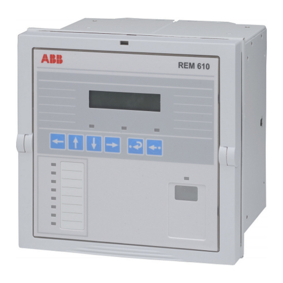
Page 3: Motor Protection Relay
Motor Protection Relay REM 610 1MRS 755121 Issued: 01.12.2003 Status: Updated Version: C/08.03.2005 Data subject to change without notice Features • Three-phase thermal overload protection - disturbance recorder data • Three-phase motor start-up supervision - recorded data of the five last events with... - Page 4 It handles fault conditions during REM 610 can equally well be used to protect, motor start up, normal run, idling, and cool- for instance, feeder cables and power trans- ing down at standstill, e.g.
-
Page 5: Setting Description
Motor Protection Relay REM 610 1MRS 755121 Settings Before the relay is connected to a system it must be assured that the relay has been given the correct settings, see table 1. Table 1: Setting values Setting Description Setting range... -
Page 6: Technical Data
Motor Protection Relay REM 610 1MRS 755121 Technical data Table 2: Dimensions Width frame 177 mm, case 164 mm Height frame 177 mm (4U), case 160 mm Depth case 149.3 mm Weight of the relay ~3.5 kg 177 (4U) Fig. 1... - Page 7 Motor Protection Relay REM 610 1MRS 755121 Technical data (cont´d) Table 4: Energizing inputs Dynamic current withstand half-wave value 250 A 1250 A Input impedance <100 mΩ <20 mΩ Table 5: Measuring range Measured currents on phases I and I as multiples of 0...50 x I...
- Page 8 Motor Protection Relay REM 610 1MRS 755121 Technical data (cont´d) Table 11: RTD/analogue inputs 100 Ω platinum Supported RTD sensors TCR0.00385 (DIN 43760) 250 Ω platinum TCR 0.00385 1000 Ω platinum TCR 0.00385 100 Ω nickel TCR 0.00618 (DIN 43760) 120 Ω...
-
Page 9: Insulation Tests
Motor Protection Relay REM 610 1MRS 755121 Technical data (cont´d) Table 13: Electromagnetic compatibility tests Voltage dips and short interruptions According to the IEC 61000-4-11 30%/10 ms 60%/100 ms 60%/1000 ms >95%/5000 ms Electromagnetic emission tests According to the EN 55011... -
Page 10: Connection Diagrams
Motor Protection Relay REM 610 1MRS 755121 Connection dia- grams Fig. 2 Residual current is measured via a core-balanced current transformer. - Page 11 Motor Protection Relay REM 610 1MRS 755121 Connection diagrams (cont´d) Fig. 3 Residual current is measured via a summation connection of the phase current transformers.
- Page 12 Motor Protection Relay REM 610 1MRS 755121 Connection diagrams (cont´d) Fig. 4 REM 610 connected to a contactor controlled motor with the trips routed to trip the contactor.
-
Page 13: Ordering Information
Motor Protection Relay REM 610 1MRS 755121 Ordering informa- When ordering REM 610 protection relays The order number identifies the protection tion and/or accessories, please specify the follow- relay type and hardware as described in Fig. ing: 4 and is labelled on the marking strip under the lower handle of the relay. - Page 14 Configuration, setting and SA system tools The following tool versions are needed to support the new functions and features of REM 610 release B: CAP 501 Relay Setting Tool CAP 501 v. 2.3.0-5 or later CAP 505 Relay Setting Tool CAP 505 v.
- Page 16 ABB Oy Distribution Automation P.O. Box 699 FI-65101 Vaasa, FINLAND Tel +358 10 22 11 Fax +358 10 224 1094 www.abb.com/substationautomation...