ABB REM 610 Operator's Manual
Motor protection relay
Hide thumbs
Also See for REM 610:
- Technical reference manual (158 pages) ,
- Operator's manual (68 pages) ,
- Product manual (36 pages)
Table of Contents
Advertisement
Quick Links
Advertisement
Table of Contents

Related Manuals for ABB REM 610


Summary of Contents for ABB REM 610
- Page 1 REM 610 Motor Protection Relay Operator’s Manual...
-
Page 3: Table Of Contents
3.2.2.2. How to change settings ........22 3.2.2.3. Configuration ............25 3.2.2.4. How to acknowledge and reset indications, output contacts and memorized values....27 3.3. Protection relay indications ............28 3.3.1. Indicator LEDs ..............28 3.3.1.1. Green indicator LED ..........28 © Copyright 2005 ABB Oy, Distribution Automation, Vaasa, FINLAND... - Page 4 REM 610 Motor Protection Relay 1MRS 752264-MUM Operator’s Manual 3.3.1.2. Yellow indicator LED ........... 28 3.3.1.3. Red indicator LED ..........29 3.3.1.4. Programmable indicator LEDs ......29 3.3.2. Indication messages ............30 3.3.2.1. Operation indication messages ......30 3.3.2.2. Disturbance recorder indication ......31 3.3.2.3.
-
Page 5: Introduction
1.1. About this manual This manual provides basic information on the protection relay REM 610 Revision B and presents detailed instructions on how to use the Human-Machine Interface (HMI) of the relay, also known as the Man-Machine Interface (MMI). In addition to the instructive part, a short chapter on commissioning and maintenance of the relay is included. - Page 6 REM 610 Motor Protection Relay 1MRS 752264-MUM Operator’s Manual • Disturbance recorder • recording time up to 80 seconds • triggering by one or several internal or digital input signals • records four analogue channels and up to eight user-selectable digital channels •...
-
Page 7: Guarantee
REM 610 1MRS 752264-MUM Motor Protection Relay Operator’s Manual Guarantee 1.4. Please inquire about the terms of guarantee of your nearest ABB representative. 1.5. Revision history Version Date Remarks 26.10.2004 Front page picture and figure 3.1.1.-1 updated. 02.03.2005 Sections 1.1., 1.3., 3.1.7., 3.1.8., 3.4.2., 3.4.3. and 9 changed. -
Page 8: Safety Information
REM 610 Motor Protection Relay 1MRS 752264-MUM Operator’s Manual Safety information Dangerous voltages can occur on the connectors, even though the auxiliary voltage has been disconnected. National and local electrical safety regulations must always be followed. The device contains components which are sensitive to electrostatic discharge. -
Page 9: Instructions
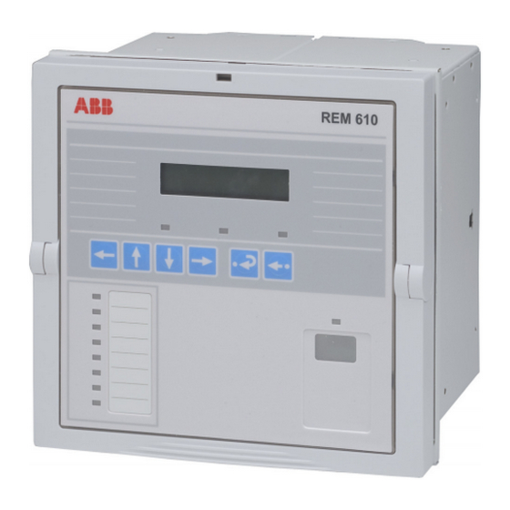
• an HMI push-button section with four arrow buttons and buttons for clear/cancel and enter • an optically isolated serial communication port with an indicator LED. FrViewREM610_b Fig. 3.1.1.-1 Front view of REM 610 1. LCD 2. HMI push-button section 3. Programmable indicator LEDs (red) 4. Indicator LEDs: •... -
Page 10: Display Modes
Display modes When the display is in the idle mode, the name of the motor drive will be displayed, which by default is - ABB -. To change the name of the motor drive, use SPA parameter M20. Fig. 3.1.2.2.-1 Display in the idle mode When the display is in the view mode, you can only view the settings. -
Page 11: How To Use The Push-Buttons
REM 610 1MRS 752264-MUM Motor Protection Relay Operator’s Manual Push increase or decrease increase or decrease Fig. 3.1.2.4.-1 Adjusting the display contrast After power start up of the relay, the factory default value of the display contrast will automatically be restored. -
Page 12: Main Menu
REM 610 Motor Protection Relay 1MRS 752264-MUM Operator’s Manual Table 3.1.3-1 Button navigation and editing Resetting latched output contacts in the idle mode for 5 s Acknowledging and resetting indications, latched output contacts and memorized values Resetting thermal level to 0 at power up 3.1.4. -
Page 13: Spa Password
REM 610 1MRS 752264-MUM Motor Protection Relay Operator’s Manual As soon as you have replaced the default HMI password, the new password will be required for altering parameter values. Once you have given the valid password, the display will remain in the setting mode until returned to the idle mode. -
Page 14: How To Select Language
Changing the SPA password 3.1.8. How to select language REM 610 allows you to choose among several different languages. The default language is English. For the selection of languages, see Fig. 3.1.8.-1. Change the display language as follows: 1. Press an arrow button to access the main menu. -
Page 15: How To Set The Real-Time Clock
REM 610 1MRS 752264-MUM Motor Protection Relay Operator’s Manual By pressing before confirming the selection, the former language will remain active and the display will be returned to the view mode. Pressing again will return the display to the idle mode. -
Page 16: How To Switch Between Front And Rear Connection
REM 610 Motor Protection Relay 1MRS 752264-MUM Operator’s Manual Parameter Menu Main Menu Group Menu MEASUREMENTS RECORDED DATA SETTINGS CONFIGURATION CONFIGURATION FUNCTION TEST/DI COMMUNICATION LANGUAGE INFO MEMORY SETTINGS FREQUENCY PASSWORD HMI CONFIGURATION Confirm TIME YY-MM-DD (00-23) TRIP CIRCUIT SUP hh.mm;ss... -
Page 17: 1.Indicator Led For Front Communication
3.1.11. How to select the protocol for rear communication REM 610 allows you to choose the communication protocol for rear connection. The selected protocol is stored in the non-volatile memory and will therefore be activated automatically after an interruption in the auxiliary voltage. -
Page 18: Hmi Operation Levels
REM 610 Motor Protection Relay 1MRS 752264-MUM Operator’s Manual Parameter Menu Main Menu Group Menu MEASUREMENTS RECORDED DATA SETTINGS CONFIGURATION CONFIGURATION FUNCTION TEST/DI CONFIGURATION REAR CONNECTION CONFIGURATION COMMUNICATION REAR PROTOCOL LANGUAGE INFO Confirm IEC 60870-5-103 REAR COM. MODULE MEMORY SETTINGS... - Page 19 REM 610 1MRS 752264-MUM Motor Protection Relay Operator’s Manual as multiples of the rated current, I , which correspond to the full load current (FLC) of the motor. I is shown as a percentage of the rated current of the θ...
-
Page 20: How To Monitor Recorded Data
REM 610 Motor Protection Relay 1MRS 752264-MUM Operator’s Manual L1 x.xx L2 x.xx L3 x.xx I0 x.xx Fig. 3.2.1.2.-2 Activating the monitoring state Note! The prerequisite for monitoring correct primary current values is that parameters M80 and M83 have been correctly set via serial communication. -
Page 21: Info
REM 610 1MRS 752264-MUM Motor Protection Relay Operator’s Manual 3.2.1.4. INFO The main menu group INFO contains information you may need when ordering repair service. 1. Press an arrow button to access the main menu. 2. Use the arrow buttons to select INFO and press... -
Page 22: How To Change Settings
REM 610 Motor Protection Relay 1MRS 752264-MUM Operator’s Manual 3.2.2.2. How to change settings The actual settings consist of the settings of group 1 or group 2, depending on which group that has been selected to be active (indicated by an asterisk “*”). The actual settings can be seen in the first parameter menu, e.g. - Page 23 REM 610 1MRS 752264-MUM Motor Protection Relay Operator’s Manual Group Menu Parameter Menus Main Menu MEASUREMENTS RECORDED DATA SETTINGS PU-SCALE :x.xx SETTINGS SETTINGS PROTECTED UNIT SETTINGS SETTINGS PROTECT. STAGES Is> In:x.xx * GRP 1 :x.xx Edit/Confirm OPT. STAGES ThA GRP 2 :x.xx...
- Page 24 REM 610 Motor Protection Relay 1MRS 752264-MUM Operator’s Manual To set functions via switchgroups: 1. Press an arrow button to access the main menu. 2. Use the arrow buttons to select the main menu group SETTINGS and the desired switchgroup menu (e.g. SGF), and press 3.
-
Page 25: Configuration
REM 610 1MRS 752264-MUM Motor Protection Relay Operator’s Manual 3.2.2.3. Configuration In general, the parameters found under CONFIGURATION are set only once by the customer, i.e. prior to commissioning of the relay. To alter a parameter: 1. Press an arrow button to access the main menu. - Page 26 REM 610 Motor Protection Relay 1MRS 752264-MUM Operator’s Manual Main Menu Group Menu Parameter Menus MEASUREMENTS RECORDED DATA SETTINGS CONFIGURATION CONFIGURATION CONFIGURATION FUNCTION TEST/DI FUNC.TEST CONFIGURATION COMMUNICATION DI STATUS DI1 STATUS LED TEST LANGUAGE DI2 STATUS INFO MEMORY SETTINGS DI3 STATUS...
-
Page 27: How To Acknowledge And Reset Indications, Output Contacts And Memorized Values
REM 610 1MRS 752264-MUM Motor Protection Relay Operator’s Manual Main Menu Group Menu Parameter Menus MEASUREMENTS RECORDED DATA SETTINGS CONFIGURATION CONFIGURATION FUNCTION TEST/DI COMMUNICATION LANGUAGE INFO MEMORY SETTINGS CONFIGURATION FREQUENCY FREQUENCY PASSWORD HMI FREQUENCY TIME TRIP CIRCUIT SUP CONFIGURATION PASSWORD HMI... -
Page 28: Protection Relay Indications
REM 610 Motor Protection Relay 1MRS 752264-MUM Operator’s Manual 3.3. Protection relay indications The operation of the relay can be monitored by means of three different kinds of indications on the HMI: • Three indicator LEDs with fixed functionality: Ready, Start/Alarm and Trip •... -
Page 29: Red Indicator Led
REM 610 1MRS 752264-MUM Motor Protection Relay Operator’s Manual • Lit indicator: A protection stage has started or generated an alarm. The start and alarm indication can be selected to be either latching or non-latching with the SGF switches. A non-latching indication will automatically be cleared when the fault has disappeared and the protection stage has been reset, whereas a latching indication will remain lit until manually cleared. -
Page 30: Indication Messages
REM 610 Motor Protection Relay 1MRS 752264-MUM Operator’s Manual For instructions on setting the switchgroups, refer to section Switchgroups. 3.3.2. Indication messages The messages give an overview of protection operations and internal relay faults. 3.3.2.1. Operation indication messages When a protection stage starts, the text START will appear on the display along with the name of the function. -
Page 31: Disturbance Recorder Indication
REM 610 1MRS 752264-MUM Motor Protection Relay Operator’s Manual indicator LEDs. The text message for the restart inhibit state is non-latching, whereas the status indication via a programmable LED can be either latching or non- latching. The restart of a motor can be inhibited by the thermal protection, the cumulative start-up time counter or an external digital input signal. -
Page 32: Indications For Internal Relay Faults (Irfs) And Warnings
REM 610 Motor Protection Relay 1MRS 752264-MUM Operator’s Manual 3.3.2.3. Indications for internal relay faults (IRFs) and warnings There are two types of fault indications; internal relay fault (IRF) indications and warnings. Internal relay faults prevent relay operation while less severe faults (called warnings) allow continued relay operation with full or reduced functionality. - Page 33 REM 610 1MRS 752264-MUM Motor Protection Relay Operator’s Manual Table 3.3.2.3-1 IRF codes Fault code Type of fault Faulty configuration set for IEC 60870-5-103 131, 139, 195, 203, Internal reference voltage error 222, 223 Error in the measuring unit May be corrected by formatting to the factory setting.
- Page 34 REM 610 Motor Protection Relay 1MRS 752264-MUM Operator’s Manual Table 3.3.2.3-2 Warning codes Trip-circuit • Error in trip circuit - Check the trip circuit for broken conductors and correct. supervision - Warning will not be displayed if trip-circuit supervision (TCS)
-
Page 35: Detachable Plug-In Unit
REM 610 1MRS 752264-MUM Motor Protection Relay Operator’s Manual 3.4. Detachable plug-in unit 3.4.1. Identifying the product The order number is found on a label under the lower handle of the relay. Warning! When checking the order number of the relay plug-in unit, be °... -
Page 36: Inserting And Changing The Battery
REM 610 Motor Protection Relay 1MRS 752264-MUM Operator’s Manual Note! Before fitting a relay plug-in unit into a relay case, check that the unit and the case have the same order number. The order number of the case is printed on the bottom plate inside the case. - Page 37 REM 610 1MRS 752264-MUM Motor Protection Relay Operator’s Manual The removed battery should be disposed of in compliance with local environmental regulations on the disposal of lithium batteries. The battery is not being charged during normal operation. When the relay is taken out of service, the battery should be removed in order to avoid discharge.
-
Page 38: Commissioning And Maintenance
Additionally, correct operation of input and output signals to and from the relay should be verified. REM 610 is a numerical protection relay with functionality implemented in the relay software configuration. Software functionality does not change over time and the relay performs extensive self-supervision during operation. -
Page 39: Maintenance Instructions
REM 610 1MRS 752264-MUM Motor Protection Relay Operator’s Manual Relay commissioning includes: 1. Verifying that the correct application-specific settings have been entered into the relay. This is done by reading the relay settings either via the HMI or serial communication and comparing these to the calculated application-specific settings. -
Page 40: Measurements Verification
REM 610 Motor Protection Relay 1MRS 752264-MUM Operator’s Manual 4.3. Measurements verification As most of the protection functions in the protection relay are based on the phase currents and earth-fault current measured by the relay, it is important to verify that the relay is measuring proper values. -
Page 41: Digital Input Test
REM 610 1MRS 752264-MUM Motor Protection Relay Operator’s Manual The table below shows the activation order and the corresponding digit flashing when a signal is being tested. Table 4.4.-1 Function test Number Function Alarm of stage θ> Trip of stage θ>... -
Page 42: Testing Of Protection Functions
REM 610 Motor Protection Relay 1MRS 752264-MUM Operator’s Manual 4.6. Testing of protection functions The short-circuit and earth-fault protection functions in the relay can be tested with the setting values used during normal operation. If other settings are used during testing, you should make sure that the original settings are re-entered after the test is completed. -
Page 43: Spare Parts
REM 610 1MRS 752264-MUM Motor Protection Relay Operator’s Manual Spare parts 5.1. Plug-in unit The relay’s construction allows a spare part in form of a plug-in unit. The outage time can therefore be reduced to a minimum in case the relay should fail. -
Page 44: Repair
Please contact the manufacturer or the nearest representative for further information on checking, overhaul and recalibration of the relay. When contacting ABB for ordering repair services, give a description of the fault and state the fault code, if applicable. -
Page 45: Ordering Information
REM 610 1MRS 752264-MUM Motor Protection Relay Operator’s Manual Ordering information Refer to the Technical Reference Manual. -
Page 46: References
REM 610 Motor Protection Relay 1MRS 752264-MUM Operator’s Manual References Other available manuals: • Technical Reference Manual, 1MRS 752263-MUM • Installation Manual, 1MRS 752265-MUM... -
Page 47: Abbreviations
REM 610 1MRS 752264-MUM Motor Protection Relay Operator’s Manual Abbreviations ASCII American Standard Code for Information Interchange CBFP Circuit-breaker failure protection Central processing unit Current transformer Digital Input Human-Machine Interface IDMT Inverse definite minimum time characteristic International Electrotechnical Commission Internal relay fault... - Page 52 ABB Oy Distribution Automation P.O. Box 699 FI-65101 Vaasa FINLAND Tel. +358 10 22 11 Fax. +358 10 224 1094 www.abb.com/substationautomation...