Table of Contents
Advertisement
Quick Links
Advertisement
Table of Contents

Related Manuals for ABB RET 670


Summary of Contents for ABB RET 670
- Page 1 Operator's manual Transformer protection IED RET 670 Innovation from...
- Page 3 Document ID: 1MRK504049-UEN Issued: December 2007 Revision: D IED product version: 1.B © Copyright 2007 ABB. All rights reserved...
- Page 4 ENSURE THAT OUR PRODUCTS ARE DEVELOPED TO THE LATEST TECHNOLOGICAL STANDARDS. AS A RESULT, IT IS POSSIBLE THAT THERE MAY BE SOME DIFFERENCES BETWEEN THE HW/SW PRODUCT AND THIS INFORMATION PRODUCT. Manufacturer: ABB AB Substation Automation Products SE-721 59 Västerås Sweden Telephone: +46 (0) 21 34 20 00 Facsimile: +46 (0) 21 14 69 18 www.abb.com/substationautomation...
-
Page 5: Table Of Contents
Status indication LEDs..............20 Indication LEDs................20 How to navigate................21 Read....................21 Change ..................22 Control..................22 Section 5 Understand the HMI tree..........23 Overview...................23 Section 6 Read measured values..........25 Overview...................25 View analog primary values..............26 Overview..................26 View analog secondary values............26 Overview..................26 RET 670 Operator's manual 1MRK504049-UEN rev. D... - Page 6 System time and synchronization.............33 System time.................33 Time synchronization..............33 Overview................33 TimeSynch................33 TimeSynchBIN...............33 TimeSynchSNTP..............34 TimeSynchDSTBegin.............34 TimeSynchDSTEnd..............34 TimeZone................34 General settings................34 Power system................34 Overview................34 Identifiers................34 Primary values................35 Three phase analog group.............35 Three phase analog summation group........35 Communication................35 Operator's manual RET 670 1MRK504049-UEN rev. D...
- Page 7 Local/Remote switch (LocalRemote, LocRemControl)...41 Control commands..............42 Single command..............42 Monitoring..................42 Overview................42 Measurements (MMXU)............42 Current phasors..............42 Voltage phasors..............42 Current sequence components (MSQI)........42 Voltage sequence components (MSQI).........43 Disturbance report (RDRE)............43 Binary signals.................43 Analog signals................43 Generic measured value............43 RET 670 Operator's manual 1MRK504049-UEN rev. D...
- Page 8 Voltage protection................48 Overview................48 Two step undervoltage protection (PUVM, 27)......48 Two step overvoltage protection (POVM, 59)......49 Two step residual overvoltage protection (POVM, 59N)..49 Overexcitation protection (PVPH, 24)........49 Frequency protection..............49 Overview................49 Underfrequency protection (PTUF, 81)........49 Operator's manual RET 670 1MRK504049-UEN rev. D...
- Page 9 Binary Input Module (BIM)............56 Signal matrix for binary input (SMBI)........57 View binary output values..............57 Overview..................57 Binary Output Module (BOM)..........57 Signal matrix for binary outputs (SMBO)........57 Function test modes.................57 Differential protection..............57 Distance protection..............57 Current protection................58 RET 670 Operator's manual 1MRK504049-UEN rev. D...
- Page 10 Two step overvoltage protection (POVM, 59)......62 Two step residual overvoltage protection (POVM, 59N)..62 Overexcitation protection (PVPH, 24)........62 View frequency protection values..........63 Underfrequency protection (PTUF, 81)........63 Overfrequency protection (PTOF, 81)........63 Rate-of-change frequency protection (PFRC, 81)....63 Operator's manual RET 670 1MRK504049-UEN rev. D...
- Page 11 Tripping logic (PTRC, 94)............69 Event counter.................69 Trip matrix logic (GGIO, 94X)..........69 Logic gate................69 Logic pulse timer..............69 Logic SR memory..............69 Logic timer set................70 Monitoring..................70 Disturbance report (RDRE)............70 Generic measured value (GGIO)...........70 Measured value expander block..........70 LEDs..................71 RET 670 Operator's manual 1MRK504049-UEN rev. D...
- Page 12 All indication LEDs..............79 Reset lockout................79 Reset counters................80 Reset autorecloser..............80 Circuit breaker................80 Circuit switch................80 Event counter.................80 Reset pulse counter...............80 LDCM clear counters..............80 Reset temperature functions............81 Section 14 Authorization..............83 Administrate users................83 Users....................84 Section 15 Glossary.................85 Glossary...................85 Operator's manual RET 670 1MRK504049-UEN rev. D...
-
Page 13: Section 1 Introduction
IED during normal service once it has been commissioned. The operator’s manual can be used to find out how to handle disturbances or how to view calculated and measured network data in order to determine the cause of a fault. RET 670 Operator's manual 1MRK504049-UEN rev. D... -
Page 14: About The Operator's Manual
The chapter “Glossary” describes words and acronyms used in the literature describing the IED. This manual does not contain any instructions for commissioning or testing. 1.1.3 Intended audience General The operator’s manual addresses the operator, who operates the IED on a daily basis. Operator's manual RET 670 1MRK504049-UEN rev. D... -
Page 15: Related Documents
The operator must be trained in and have a basic knowledge of how to operate protection equipment. The manual contains terms and expressions commonly used to describe this kind of equipment. 1.1.4 Related documents Documents related to RET 670 Identity number Operator’s manual 1MRK 504 049-UEN Installation and commissioning manual... -
Page 16: Revision Notes
Section 1 Introduction 1.1.5 Revision notes Revision Description No functionality added. Minor changes made in content due to problem reports. Operator's manual RET 670 1MRK504049-UEN rev. D... -
Page 17: Section 2 Safety Information
Always avoid touching the circuitry when the cover is removed. The product contains electronic circuitries which can be damaged if exposed to static electricity (ESD). The electronic circuitries also contain high voltage which is lethal to humans. RET 670 Operator's manual 1MRK504049-UEN rev. D... -
Page 19: Section 3 Overview
To identify the IED, open the diagnostics menu. The identity of the IED along with other data is found under: Diagnostics/IED status/Product Identifiers The type of IED, the main function type, its serial number, ordering number and production date are found here. RET 670 Operator's manual 1MRK504049-UEN rev. D... -
Page 21: Section 4 Understand The Local Human-Machine Interface
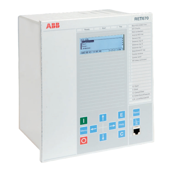
IED operates. The configuration designer can add functions that alert to events requiring the attention of the operator. Figure 1: 1/2 x 19” case and 1/1 x 19” case with small and medium LCDs RET 670 Operator's manual 1MRK504049-UEN rev. D... -
Page 22: Keypad
The Local/Remote key is used to set the IED in local or remote control mode. This key opens the reset screen. The E key starts editing mode and confirms setting changes when in editing mode. Table continued on next page Operator's manual RET 670 1MRK504049-UEN rev. D... -
Page 23: Key Activated Screens
LEDs” and “All indication LEDs” submenus. To reset a counter, the actual counter must first be selected. The submenus and the their structures are discussed in the “Reset” chapter of this document. RET 670 Operator's manual 1MRK504049-UEN rev. D... -
Page 24: Lcd
LED Indication Information Green: Steady In service Flashing Internal failure Dark No power supply Yellow: Steady Dist. rep. triggered Flashing Terminal in test mode Red: Steady Trip command issued 4.5.2 Indication LEDs Operator's manual RET 670 1MRK504049-UEN rev. D... -
Page 25: How To Navigate
Press the down arrow key to move from the Single line diagram to the desired submenu. • Use the right arrow key to move downwards in the HMI tree until the desired parameter is displayed. RET 670 Operator's manual 1MRK504049-UEN rev. D... -
Page 26: Change
The Open or Close commands are issued by pressing the O or I keys; The user is requested to confirm the command in a pop-up window. E confirms a command; C cancels it. Interlocking or synchrocheck conditions may cause other query windows to pop-up. Operator's manual RET 670 1MRK504049-UEN rev. D... -
Page 27: Section 5 Understand The Hmi Tree
Disturbance records • Settings • Diagnostics • Test • Reset • Authorization • Language Each submenu is in turn made up of several other submenus. The overall structure is illustrated in figure 3. RET 670 Operator's manual 1MRK504049-UEN rev. D... - Page 28 Current Current Trip Values monitoring monitoring Sequence functions Installed functions Multi- Compon- Recalc purpose ents Distance to Fault Control Voltage Sequence Monitor Compon- ents etc. en05000696.vsd Figure 3: Overview of the tree structure Operator's manual RET 670 1MRK504049-UEN rev. D...
-
Page 29: Section 6 Read Measured Values
For example, it is possible to equip a 1/1 x 19” case IED with 14 I/O modules. In reality fewer I/O modules may be installed. In the measurements menu the operator will only see data from the hardware and software installed. RET 670 Operator's manual 1MRK504049-UEN rev. D... -
Page 30: View Analog Primary Values
Measurements/Analog Mean Values/mA modules/Instance No./AI Displays input data from the milli-ampere module which has six inputs. Each input has a range of +/- 20 mA. The value displayed on the screen is however dependant Operator's manual RET 670 1MRK504049-UEN rev. D... -
Page 31: Signal Matrix For Ma Inputs (Smmi)
(I2) and zero sequence (I0) current values for a three phase line, both magnitude and phase angle for each component are displayed. These indicate how well balanced a system is. In an ideal balanced system the zero sequence current RET 670 Operator's manual 1MRK504049-UEN rev. D... -
Page 32: Voltage Sequence Component
Three sets of values are shown. This data indicates how well balanced the system is. View metering values Measurements/Metering The output data generated under metering is from the pulse counter and includes data about the status of the counter and counter values. Operator's manual RET 670 1MRK504049-UEN rev. D... -
Page 33: Section 7 Event List
Events displays recorded events such as trips and breaker opened or closed. Events Displays a list of events in chronological order and where each event has a time stamp. The latest event is at the top of the list. RET 670 Operator's manual 1MRK504049-UEN rev. D... -
Page 35: Section 8 Handle Disturbances
The path in the HMI is shown below. Disturbance records/Record xx/Indications 8.2.3 View event recordings The Event recording section in the Disturbance report shows the recording number. The path in the HMI is shown below. Disturbance records/Record xx/Event recording RET 670 Operator's manual 1MRK504049-UEN rev. D... -
Page 36: View Trip Values
Using the manual trigger generates an instant disturbance report. Use this function to get a snapshot of the monitored line. Follow the path below and answer yes in the Execute manual trig dialog box. Disturbance Records/Manual Trig Operator's manual RET 670 1MRK504049-UEN rev. D... -
Page 37: Section 9 Read And Change Settings
BIN, Time synch SNTP, Time synch DST Begin, Time synch DST End and Time synch time zone. The settable parameters are found under each category. 9.1.2.2 TimeSynch Settings/Time/Synchronization/TimeSynch Here the parameters FineSyncSource, CourseSyncSrc and SyncMaster are switched on or off. 9.1.2.3 TimeSynchBIN Settings/Time/Synchronization/TimeSynchBIN RET 670 Operator's manual 1MRK504049-UEN rev. D... -
Page 38: Timesynchsntp
Identifiers, Primary values, three phase analog group and three phase analog sum group. 9.2.1.2 Identifiers Settings/General Settings/Power System/Identifiers Displays list with Station Name, Station Number, Object Name, Object Number, Unit Name and Unit Number. Operator's manual RET 670 1MRK504049-UEN rev. D... -
Page 39: Primary Values
The IP address, IP mask and Link for the Optical Ethernet card at the rear of the IED are set here. Settings/General settings/Communication/TCP-IP configuration/Rear OEM- Port CD The same as the above but with different IP address if a second port is used. RET 670 Operator's manual 1MRK504049-UEN rev. D... -
Page 40: Spa, Lon And Iec 60870-5-103 Settings
Settings/General settings/Communication/SLM configuration/Rear optical SPA-IEC port In this submenu SPA or IEC is chosen and the necessary settings for the respective communication protocols are made. Settings/General settings/Communication/SLM configuration/Rear optical SPA-IEC port/Protocol selection SPA or IEC103 operation. Operator's manual RET 670 1MRK504049-UEN rev. D... -
Page 41: Ldcm
The up to 60 instances of MulticommandReceive settings available here allow the user to adjust the maximum and minimum cycle time, the pulse duration and mode of operation. The mode of operation is either steady or pulsed. Settings/General Settings/Communication/Station communication/IEC61850– 8–1 RET 670 Operator's manual 1MRK504049-UEN rev. D... -
Page 42: Analog Modules
Settings for binary inputs and outputs (BIM, BOM, IOM), and under each binary module there are one or more adjustable parameters. In the I/O modules folder there is also a “reconfigure” setting that starts a dialog box prompting the user to confirm Operator's manual RET 670 1MRK504049-UEN rev. D... -
Page 43: Hmi
Settings/General Settings/HMI/Functions The settings here are used to determine the way information is presented in the HMI. 9.2.4.5 Reference channel service values Settings/General settings/HMI/Reference channel service values The phase angle reference is selected here. RET 670 Operator's manual 1MRK504049-UEN rev. D... -
Page 44: Change Lock
These are the parameters for among others Bay control, Switch controller, Reservation input, Circuit breakers and Circuit switches. The parameters include delay times, dependencies, pulse times and characteristics. 9.2.6.2 Bay control (QCBAY) Settings/General Settings/Control/Apparatus Control/Bay Control/CBO Operator's manual RET 670 1MRK504049-UEN rev. D... -
Page 45: Reservation Input (Resin)
9.2.6.8 Local/Remote switch (LocalRemote, LocRemControl) Settings/General Settings/Control/Apparatus control/LocalRemote Displays six instances of the local/remote function (LR) that permit the user to set the control mode. RET 670 Operator's manual 1MRK504049-UEN rev. D... -
Page 46: Control Commands
3I0, for positive sequence current it is I1 and for negative sequence current it is I2. There are three sets of settings with seven categories of parameter settings per set (CSQ) Operator's manual RET 670 1MRK504049-UEN rev. D... -
Page 47: Voltage Sequence Components (Msqi)
These settings are used to define the range of values used in the function block and to set the threshold values. This is a generic function and therefore the input values depend on the application. 9.2.8.11 Event function Settings/General settings/Monitoring/Event function RET 670 Operator's manual 1MRK504049-UEN rev. D... -
Page 48: Binary Signal Status Report
Each instance has 1 setting and four settable parameters. The setting “operation” is used to turn the function on or off. The parameters are adjusted to change cycle times, pulse counter criteria and the like. Operator's manual RET 670 1MRK504049-UEN rev. D... -
Page 49: Setting Group N
Displays up to two instances of T3D with 13 settings each. The settings for this function are identical to "Transformer differential protection, two winding (PDIF, 87T)" 9.3.2.4 Restricted earth fault protection (PDIF, 87N) Settings/Setting group N/Differential protection/LowImpREF(PDIF) RET 670 Operator's manual 1MRK504049-UEN rev. D... -
Page 50: High Impedance Differential Protection (Pdif, 87X)
Displays 19 settings including minimum operating current for both phase-phase and phase-earth fault loops. 9.3.3.4 Directional impedance (RDIR) Settings/Setting Group N/Distance protection/DirectionalImpedance(RDIR) Includes settings for rated current, voltage and impedance direction angles. 9.3.3.5 Power swing detection (RPSB, 78) Settings/Setting Group N/Distance protection/PowerSwingDetection(RPSB) Operator's manual RET 670 1MRK504049-UEN rev. D... -
Page 51: Automatic Switch Onto Fault Logic (Psof)
Displays three instances of IEF with four settable parameters per instance. The settable parameters are operation (On or Off), base setting for current magnitude, the threshold current as a percentage of Ibase, and the multiplier for the current threshold level. RET 670 Operator's manual 1MRK504049-UEN rev. D... -
Page 52: Four Step Residual Overcurrent Protection (Pefm, 51N/67N)
On or Off, set rated quantities or make other adjustments necessary for the fine tuning of the function itself. 9.3.5.2 Two step undervoltage protection (PUVM, 27) Settings/Setting Group N/Voltage protection/UnderVoltage2Step(PUVM) Operator's manual RET 670 1MRK504049-UEN rev. D... -
Page 53: Two Step Overvoltage Protection (Povm, 59)
Underfrequency function the Operation setting must be On. Once changes have been made to settings, it is essential that these changes are properly saved in the IED. 9.3.6.3 Overfrequency protection (PTOF, 81) Settings/Setting Group/Frequency protection/Overfrequency RET 670 Operator's manual 1MRK504049-UEN rev. D... -
Page 54: Rate-Of-Change Frequency Protection (Pfrc, 81)
There are six instances of Fuse failure supervision parameters for setting rated current, voltage, operation mode and 14 other parameters. 9.3.8.2 Current circuit supervision (RDIF) Settings/Setting Group N/Secondary system supervision/ CurrentCircuitSupervision(RDIF) Operator's manual RET 670 1MRK504049-UEN rev. D... -
Page 55: Fuse Failure Supervision (Rfuf)
Displays five instances of the trip logic function (TRP) with five settable parameters per instance. The settable parameters include operation, tripping order, trip lockout and minimum duration of trip output signal. 9.3.10.3 Trip matrix logic (GGIO, 94) Settings/Setting group N/TripLogic(GGIO) RET 670 Operator's manual 1MRK504049-UEN rev. D... -
Page 56: Logicgate
Language Under the language part of the main menu the language options available in the HMI are located. These vary depending on the configuration ordered. Operator's manual RET 670 1MRK504049-UEN rev. D... -
Page 57: Section 10 Diagnose Ied Status
By following the menu path below the configuration of all hardware in the IED is displayed as a list. Diagnostics/IED Status/Installed HW The list includes the slot number, the module name (Card) and its article number. RET 670 Operator's manual 1MRK504049-UEN rev. D... -
Page 59: Section 11 Test The Ied
Data shown here is mainly trip and start related. Frequency protection includes measurements from frequency functions. Measurements show trip, start and similar data. Multipurpose protection includes measurements showing data regarding trip signals, start signals, current and voltage values. RET 670 Operator's manual 1MRK504049-UEN rev. D... -
Page 60: Ied Test Mode
Binary input modules with enhanced pulse counting capabilities can receive pulses used for power measurement. The number of pulses received is used to measure power. 11.3.1.1 Binary Input Module (BIM) Test/Binary Input Values/Binary Input Modules/BIM Operator's manual RET 670 1MRK504049-UEN rev. D... -
Page 61: Signal Matrix For Binary Input (Smbi)
Function test modes 11.5.1 Differential protection Test/Function test modes/Differential protection Test of the low and high impedance restricted earth fault protection as well as transformer differential protection testing. 11.5.2 Distance protection Test/Function test mode/Distance protection RET 670 Operator's manual 1MRK504049-UEN rev. D... -
Page 62: Current Protection
Test of current circuit supervision and fuse failure supervision. 11.5.8 Control Test/Function test modes/Control Test of synchrocheck and energizing check function. 11.5.9 Logic Test/Function test modes/Logic Test of trip logic and event counter functions. Operator's manual RET 670 1MRK504049-UEN rev. D... -
Page 63: Function Status
RET 670 Operator's manual 1MRK504049-UEN rev. D... -
Page 64: High Impedance Differential Protection (Pdif, 87X)
11.6.4 Current protection Viewable data under Current protection consists mainly of trip status data under the various categories of current protection which include overcurrent protection, thermal overload, pole discordance and variations of these. Operator's manual RET 670 1MRK504049-UEN rev. D... -
Page 65: Instantaneous Phase Overcurrent Protection (Pioc, 50)
Displays up to three instances of TTR with 12 measurements per instance. The measurements show trip data, start signal status, time to reset, alarm signals and others. 11.6.4.7 Breaker failure protection (RBRF, 50BF) Test/Function status/Current protection/BreakerFailure(RBRF)/BFP RET 670 Operator's manual 1MRK504049-UEN rev. D... -
Page 66: Breaker Failure Protection, Single Phase Version (Rbrf, 50Bf)
Two step residual overvoltage protection (POVM, 59N) Test/Function status/Voltage protection/ResidualOverVoltage2Step(POVM)/ Displays up to three instances of TRV with six measurements per instance. The measurements include operate/trip and signal data. 11.6.5.4 Overexcitation protection (PVPH, 24) Test/Function status/Voltage protection/Overexcitation(PVPH)/OEX Operator's manual RET 670 1MRK504049-UEN rev. D... -
Page 67: View Frequency Protection Values
The data generated by the multipurpose function comprises various trip and start signals, block of second harmonic detection, various measured current values and the angle between current and voltage. 11.6.7.1 General current and voltage protection (PGPF) Test/Function status/Multipurpose protection/GeneralCurrentVoltage(PGPF)/ RET 670 Operator's manual 1MRK504049-UEN rev. D... -
Page 68: Secondary Circuit Supervision
Test/Function status/Control/SynchroCheck(RSYN)/SYN Displays up to five instances of SYN with 21 measurements per instance. These include information about which lines and buses selected, various voltage and frequency differences and feedback on synchronization status. Operator's manual RET 670 1MRK504049-UEN rev. D... -
Page 69: Apparatus Control (Apc)
Interlock, one and a half circuit breaker connection Test/Function status/Control/Apparatus control/Interl11/2CBConn/IKx Displays 10 measurements per CB arrangement (IKx) showing the conditions applicable to breakers disconnectors and earth switches in the one and half CB arrangement. RET 670 Operator's manual 1MRK504049-UEN rev. D... -
Page 70: Interlock, One And A Half Circuit Breaker Line A
For example, the measurement named QB12OPTR indicates whether or not QB1 and QB2 are in the open position. If the Operator's manual RET 670 1MRK504049-UEN rev. D... -
Page 71: Interlock, Transformer Bay
(CNT_VAL), the latest value of the error indication during command (L_CAUSE) and error indication during command (CAUSE) which have integer outputs, the measurement outputs have boolean values indicating the status of processes and devices. 11.6.11.17 Bay reserve Test/Function status/Control/Apparatus control/BayReserve RET 670 Operator's manual 1MRK504049-UEN rev. D... -
Page 72: Reservation Input (Resin)
Under this part of the HMI tree there are the following three submenus: • IED Commands • Function Commands • User Defined Commands Various IED, function and user defined command data can be viewed here. Operator's manual RET 670 1MRK504049-UEN rev. D... -
Page 73: Logic
Displays one value in boolean form indicating output from the pulse timer. 11.6.13.6 Logic SR memory Test/Function status/Logic/LogicSRMemory Displays 40 instances of the function (SM). There are two measurement parameters per instance, SMnn OUT (Output) and SMnn N_OUT (Output inverted). The output RET 670 Operator's manual 1MRK504049-UEN rev. D... -
Page 74: Logic Timer Set
11.6.14.3 Measured value expander block Test/Function status/Monitoring/MeasValExpander Displays up to 66 instances of the function block (XP). These show the boolean values assigned to the integer values generated by analog inputs. Operator's manual RET 670 1MRK504049-UEN rev. D... -
Page 75: Leds
11.6.16 Communications The communication output data available under Test includes remote communication and station communication. RET 670 Operator's manual 1MRK504049-UEN rev. D... -
Page 76: Remote Communication
Each set of output data has 16 signals. Other information displayed here shows whether there has been a change in data and whether data is valid. 11.6.17 View setting groups Test/Function status/Setting groups Displays six setting groups and indicates which of them is in use. Operator's manual RET 670 1MRK504049-UEN rev. D... -
Page 77: View Test Data
Test LEDs Test/LED test The Test LEDs menu enables the operator to activate LEDs manually. LEDs that do not light up are defective. Defective LEDs are also logged in Disturbance records under Monitoring. RET 670 Operator's manual 1MRK504049-UEN rev. D... -
Page 79: Section 12 Control And Supervise The Bay
Locating and using the single line diagram It is possible to navigate the SLD screen using the up and down keys on the IED keypad. The apparatus under control is highlighted as the user moves from symbol RET 670 Operator's manual 1MRK504049-UEN rev. D... - Page 80 The symbols used in the Single Line Diagram (SLD) are described in the table below Symbol Description Autotransformer xx05000227.vsd Busbar xx05000228.vsd Capacitor xx05000231.vsd Circuit breaker xx05000232.vsd Damping Coil xx05000233.vsd Current Transformer xx05000234.vsd Earth xx05000235.vsd Feeder system xx05000236.vsd Generator xx05000237.vsd Table continued on next page Operator's manual RET 670 1MRK504049-UEN rev. D...
-
Page 81: Control Screen Messages
They can also warn the user as to conditions that are a hindrance to the intended action, such as an interlocking condition. The user may be given the choice to override certain conditions. RET 670 Operator's manual 1MRK504049-UEN rev. D... -
Page 83: Section 13 Reset
The reset lockout facility is used to undo a lockout condition caused by a such a trip. Reset/Reset lockout/Trip logic(PTRC) In the dialog box that appears, choose YES to reset. RET 670 Operator's manual 1MRK504049-UEN rev. D... -
Page 84: Reset Counters
The Pulse counter reset function is found in the Reset counters menu in the HMI tree. Reset/Reset counters/Pulse counter(GGIO:12) In the dialog box that appears, choose YES to reset. 13.1.3.6 LDCM clear counters Reset/Reset LDCM counters Operator's manual RET 670 1MRK504049-UEN rev. D... -
Page 85: Reset Temperature Functions
The Reset temperature function under the Reset counters menu offers the following reset possibilities. These are outlined below. Reset/Reset temperature/ThermalOverload1TimeConstant(PTTR.25) In the dialog box that appears, choose YES to reset. Reset/Reset temperature/ThermalOverload2TimeConstant(PTTR.25) In the dialog box that appears, choose YES to reset. RET 670 Operator's manual 1MRK504049-UEN rev. D... -
Page 87: Section 14 Authorization
The HMI path is as follows: Authorization/Administrator To log in as administrator Write abb in place of the three first * symbols. Place the cursor at the fourth * symbol. Press the "down arrow" until the $ symbol appears directly behind abb. Enter User categories There are three different user categories, these are listed below: •... -
Page 88: Users
Once users have been registered in the system by the administrator, they can log on and off, and change their passwords under the User menu. The HMI path from the main menu to the user menu is as follows: Authorization/User Operator's manual RET 670 1MRK504049-UEN rev. D... -
Page 89: Section 15 Glossary
Section 15 Glossary Section 15 Glossary About this chapter This chapter contains a glossary with terms, acronyms and abbreviations used in ABB technical documentation. 15.1 Glossary Alternating current A/D converter Analog to digital converter ADBS Amplitude dead -band supervision Analog digital conversion module, with time synchronization... - Page 90 Discrete Fourier transform DIP-switch Small switch mounted on a printed circuit board DLLB Dead line live bus Distributed Network Protocol as per IEEE/ANSI Std. 1379-2000 Disturbance recorder DRAM Dynamic random access memory Disturbance report handler Operator's manual RET 670 1MRK504049-UEN rev. D...
- Page 91 High speed auto reclosing High voltage HVDC High voltage direct current IDBS Integrating dead band supervision International Electrical Committee IEC 60044-6 IEC Standard, Instrument transformers – Part 6: Requirements for protective current transformers for transient performance RET 670 Operator's manual 1MRK504049-UEN rev. D...
- Page 92 IRIG-B: InterRange Instrumentation Group Time code format B, standard 200 International Telecommunications Union Local area network LIB 520 High voltage software module Liquid crystal display LDCM Line differential communication module Local detection device Operator's manual RET 670 1MRK504049-UEN rev. D...
- Page 93 Bus or LAN used at the process level, that is, in near proximity to the measured and/or controlled components Power supply module Parameter setting tool PT ratio Potential transformer or voltage transformer ratio PUTT Permissive underreach transfer trip RASC Synchrocheck relay, COMBIFLEX RET 670 Operator's manual 1MRK504049-UEN rev. D...
- Page 94 Trip circuit supervision Transmission control protocol. The most common transport layer protocol used on Ethernet and the Internet. TCP/IP Transmission control protocol over Internet Protocol. The de facto standard Ethernet protocols incorporated into 4.2BSD Operator's manual RET 670 1MRK504049-UEN rev. D...
- Page 95 Three times zero-sequence current. Often referred to as the residual or the earth-fault current Three times the zero sequence voltage. Often referred to as the residual voltage or the neutral point voltage RET 670 Operator's manual 1MRK504049-UEN rev. D...