GE Druck DPI 620 Genii User Manual
Advanced modular calibrator
Hide thumbs
Also See for Druck DPI 620 Genii:
- Quick start manual (154 pages) ,
- User manual (179 pages)
Table of Contents
Advertisement
User Manual
GE Measurement & Control
Druck DPI 620 Genii
Advanced Modular Calibrator
K0541
© 2013 General Electric Company. All Rights Reserved. Specifications are
subject to change without notice. GE is a registered trademark of General
Electric Company. Other company or product names mentioned in this
document may be trademarks or registered trademarks of their respective
companies, which are not affiliated with GE
Druck DPI620 Genii
Advertisement
Table of Contents

Related Manuals for GE Druck DPI 620 Genii


Summary of Contents for GE Druck DPI 620 Genii
- Page 1 K0541 © 2013 General Electric Company. All Rights Reserved. Specifications are subject to change without notice. GE is a registered trademark of General Electric Company. Other company or product names mentioned in this document may be trademarks or registered trademarks of their respective...
-
Page 2: Table Of Contents
Power Off ........................... 19 1.11.3 Sleep Mode ........................19 1.11.4 Power up from Sleep Mode ..................19 1.12 Druck DPI 620 Genii, Modes ....................20 1.12.1 Dashboard navigation ....................21 1.12.2 Set Date, Time and Language ................. 22 1.12.3 Themes ..........................22 1.12.4... - Page 3 User Manual Druck DPI620 Genii 1.13.2 Upgrading the Software ..................... 23 1.14 Maintenance..........................28 1.14.1 Cleaning ..........................28 1.15 Instrument Return........................29 1.15.1 Returned Material Procedure for USA ..............29 1.15.2 Returned Goods Procedure for Europe ............... 30 1.15.3 Instrument Disposal in the European Union ............. 31 1.16 Packaging for Storage or Transportation ..............
- Page 4 User Manual Druck DPI620 Genii 2.13 Example Procedure: Switch Test ..................57 2.14 Measure Pressure: IDOS Option ..................60 2.14.1 IDOS Option Assembly Instructions ..............61 2.14.2 IDOS Function Procedures ..................62 2.15 Error Indications ........................63 Pressure Indicator Operation (MC620) ..................64 Parts and Assembly ........................
- Page 5 User Manual Druck DPI620 Genii 5.2.2 Define each Input Channel ..................... 87 Analysis Function ........................89 Run Procedure ........................... 90 5.4.1 Sequence to Upload and Download File ..............91 HART® Operations ..........................92 HART® Menu Operations ..................... 92 Start-up ............................93 HART®...
- Page 6 User Manual Druck DPI620 Genii 7.4.2 Troubleshooting ........................ 118 Device Focus View ........................ 119 The Navigation Menu Tree....................121 7.6.1 Block Header bar......................122 Functional Group View ....................... 123 7.7.1 Displaying Parameter Help ..................125 7.7.2 Refreshing Data ........................ 126 7.7.3 Editing Values ........................
- Page 7 User Manual Druck DPI620 Genii 8.10 Procedures (CH1): Resistance (source) ................ 159 8.11 Procedures (CH1): TC mV (measure or source) ............161 8.12 Procedures (CH1): Cold Junction (TC method) and CJ (measure) ....162 8.13 Procedures (CH1): AC mV/Volts (measure) ..............165 8.14 Procedures: Pressure Indicator Modules (PM 620) ..........
-
Page 8: Overview
User Manual Druck DPI620 Genii Overview The Druck DPI620 Genii is a battery-powered instrument for electrical measure and source operations and HART® communications. The Druck DPI620 Genii also supplies the power and user interface functions for all optional items. The touch-screen displays up to six different parameters. Equipment in the Box The following items are supplied with the Druck DPI 620 Genii:... -
Page 9: Optional Items
(MC 620) or a Pressure Station (PV 62X) to enhance the pressure measurement functionality. • Pressure Stations, PV 62X, if the Druck DPI 620 Genii is installed in a Pressure Station, it becomes a fully integrated pressure calibrator. -
Page 10: General Safety Precautions
User Manual Druck DPI620 Genii General Safety Precautions Read and obey all the operator's local Health and Safety regulations and Safe Working Procedures or Practices. When doing a procedure or task: • Use only the approved tools, consumable materials and spares to operate and maintain the equipment. •... -
Page 11: General Warnings
User Manual Druck DPI620 Genii General Warnings • It is dangerous to ignore the specified limits for the instrument or its related accessories. This can cause injuries. • If the equipment is used in a manner not specified by the manufacturer, the protection provided by the equipment may be impaired. -
Page 12: Electrical Warnings
To prevent an explosion or fire, do not short circuit, do not disassemble, and keep it safe from damage. • To prevent an explosion or fire, use only the GE specified battery (Part: 191-356), power supply (Part: 191-339) and battery charger (Part: IO620-CHARGER). - Page 13 User Manual Druck DPI620 Genii • Note that the operating and storage temperature range of the mains PSU does not match that of the DPI620. Mains PSU operating temperature range 0°C to +40°C, storage temperature range -40°C to +70°C. • The DC input to the DPI620 Genii is rated at 5V (+/-5%). Maximum current 2 Amps.
- Page 14 User Manual Druck DPI620 Genii The following summary of installation and measurement overvoltage categories are derived from IEC61010-1. The overvoltage categories indicate the severity of overvoltage transients Overvoltage Description Category Overvoltage category I has the least severe overvoltage transients. Generally CAT I CAT I equipment is not designed to be directly connected to the mains supply.
-
Page 15: Pressure Warnings
• To prevent damage to the Druck DPI 620 Genii, only use it within the specified pressure limits. • Do not exceed the maximum pressures stated in the appropriate component manual for the unit under test. -
Page 16: Preparing The Instrument
User Manual Druck DPI620 Genii Preparing the Instrument On receipt of the instrument check the contents in the box, listed in section 1.1. It is recommended to retain the box and packaging for future use. Install the Battery Remove the five Pozidriv screws (A) (Ref: Figure 1-1). Remove the battery cover. - Page 17 User Manual Druck DPI620 Genii Figure 1-1 06 June 2013 K0541 issue 1 Page 17 of 175...
-
Page 18: Charge The Battery
User Manual Druck DPI620 Genii 1.10 Charge the Battery Connect the DC power supply into the +5V DC connection on the side of the unit (Ref: Figure 1-2). The battery can also be charged using the USB connections (Ref: Figure 1-2). The unit can be On or Off when charging. -
Page 19: Basic Modes
User Manual Druck DPI620 Genii 1.11 Basic Modes 1.11.1 Power On From OFF – momentarily press the power button until the display flashes (Ref: Figure 1-2) . 1.11.2 Power Off Press and hold power button until the screen is blank. 1.11.3 Sleep Mode Press and release power button for sleep mode. -
Page 20: Druck Dpi 620 Genii, Modes
User Manual Druck DPI620 Genii 1.12 Druck DPI 620 Genii, Modes The Druck DPI 620 Genii can be used as follows: • Calibrator (with independent functions on each of six channels). - Data logging capabilities - Documenting capabilities • HART® Communicator. -
Page 21: Dashboard Navigation
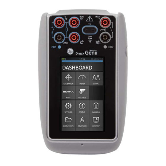
User Manual Druck DPI620 Genii 1.12.1 Dashboard navigation The Dashboard is navigated by swiping a finger from top to bottom while touching the screen. Functions screens are navigated by swiping a finger from right to left while touching the screen. Figure 1-3 Dashboard Note: Fieldbus is not installed on all units 06 June 2013... -
Page 22: Set Date, Time And Language
DASHBOARD >> SETTINGS >> THEME 1.12.4 Druck DPI 620 Genii Manual Select the Help icon on the Dashboard to access the manual. All the information required to operate the Druck DPI 620 Genii, is in the Help section of the Dashboard which is accessed by selecting: DASHBOARD >>... -
Page 23: Software And Firmware Upgrades
Note: If the software revision number is highlighted red then an upgrade is available. 1.13.2 Upgrading the Software Follow the website instructions to download the files onto a USB flash memory drive. www.ge-mcs.com 1. Select: DASHBOARD >> ADVANCED 2. Enter the calibration PIN: 5487 3. Select the button. - Page 24 User Manual Druck DPI620 Genii • Upgrade the Application software and SDC625 Application. 1. Copy the ‘AMC’ application folder into the root of a USB flash memory device. 2. Put the USB flash memory drive in the USB type A connector. 3.
- Page 25 User Manual Druck DPI620 Genii • Upgrade the HART processor Application and Boot Loader 1. Create a folder named ‘HART’ in the root of a USB flash memory device. 2. Copy the files ‘DK416.s19’ and ‘DK417.s19’ into the ‘HART’ folder. 3.
- Page 26 User Manual Druck DPI620 Genii • Upgrade the HART Device Library By default the HART device library is stored on the micro SD Card. 1. Set the DPI620 Genii USB client port to Storage Device mode by selecting: DASHBOARD >> DEVICES >>...
- Page 27 User Manual Druck DPI620 Genii Figure 1-4 Hart DD Directory Structure Note: • If a mistake is made during upgrade and there are no files to upload, follow the on-screen instructions and complete the procedure. • When an upgrade completes normally, the initial operation of the touch screen may be slower (a period of approximately 30 seconds).
-
Page 28: Maintenance
User Manual Druck DPI620 Genii 1.14 Maintenance The DPI620 Genii instrument contains no user serviceable parts and should be returned to a GE service center for repair. 1.14.1 Cleaning CAUTION Do not use solvents or abrasive materials. Clean the case and display with a lint free cloth and a weak detergent solution. -
Page 29: Instrument Return
If the instrument is unserviceable and requires a repair, return to a GE Service Centre or Approved Service Agent. Web site: www.ge-mcs.com Contact the GE Service Centre, either by 'phone, fax or e-mail to obtain a Returned Material Authorization (RMA) number, providing the following information: Product (i.e. -
Page 30: Returned Goods Procedure For Europe
If the instrument is unserviceable and requires a repair, return to a GE Service Centre or Approved Service Agent. Web site: www.ge-mcs.com Contact the GE Service Centre, either by 'phone, fax or e-mail to obtain a Returned Material Authorization (RMA) number, providing the following information: Product (i.e. -
Page 31: Instrument Disposal In The European Union
Do not dispose of this product or its battery as household waste. Use an approved organization that collects and/or recycles the applicable item. For more information contact • GE Sensing customer service department: (www.ge-mcs.com) • Local government office. 06 June 2013 K0541 issue 1... -
Page 32: Packaging For Storage Or Transportation
User Manual Druck DPI620 Genii 1.16 Packaging for Storage or Transportation To store the unit or to return the unit for calibration or repair carry out the following procedures: Pack the Instrument. To return the instrument for calibration or repair, complete the return goods procedure (Ref: 1.15). -
Page 33: Electrical Operations
User Manual Druck DPI620 Genii Electrical Operations Basic Calibrator Operation Select: DASHBOARD >> CALIBRATOR Select the channel by performing the following tasks: • Swipe to the TASK MENU by swiping the display from right to left. Figure 2-1 Task Menu 06 June 2013 K0541 issue 1 Page 33 of 175... - Page 34 User Manual Druck DPI620 Genii • Select the CUSTOM TASK option. This will allow the user to set up Channels 1 & 2 in addition to the Pressure Channels, USB (IDOS) and Communications (HART or Foundation Fieldbus). Figure 2-2 Task Settings Menu 06 June 2013 K0541 issue 1 Page 34 of 175...
- Page 35 User Manual Druck DPI620 Genii • Select CH1 or CH2 to enter the CHANNEL SETTINGS menu. P1 and P2 are used for pressure measurements. (Refer to Section 3). IDOS is used for external IDOS sensors. (Refer to Section 2.14) is used for Hart® and FOUNDATION™ Fieldbus. (Refer to sections 6 and 7).
- Page 36 User Manual Druck DPI620 Genii Setup a channel for measurement. • DIRECTION selects source or measure for the selected function • FUNCTION selects the function required (eg Current or Voltage). For more options scroll down the menu by swiping the display from bottom to top. •...
- Page 37 User Manual Druck DPI620 Genii Other Task Menu Options available are: • DEFAULT – Returns the settings to the default settings Additional options are also included for common tasks. For example: • Thermocouple Transmitter – Ch1 TC Source Ch2 mA Measure •...
-
Page 38: Set The Function Utility Options
User Manual Druck DPI620 Genii Set the Function Utility Options For each function only one utility may be active. Not all source and measure functions have associated utilities. For all options the button resets the additional readings. 2.2.1 Max/Min This utility is only available with measure functions. The additional values displayed show the minimum, maximum, and average values of the input signal. -
Page 39: Switch Test
User Manual Druck DPI620 Genii 2.2.2 Switch Test This utility is available with measure or source functions. The additional values displayed show signal values (measure or source) when the instrument detects a switch opening and closing. The difference between the two values is displayed as hysteresis value for the switch. -
Page 40: Relief Valve
User Manual Druck DPI620 Genii 2.2.3 Relief Valve This utility is only available with measure functions. This utility tests circuits or mechanisms that have a cut-out response when an input reaches a defined threshold value. The utility allows the user to select a mode of operation which can be rising or falling. - Page 41 User Manual Druck DPI620 Genii Rising Falling Figure 2-7 Relief Value Utility 06 June 2013 K0541 issue 1 Page 41 of 175...
-
Page 42: Measurement Display Options
User Manual Druck DPI620 Genii Measurement Display Options There are 2 display views in the CALIBRATOR screen when multiple channels are in use: • Figure 2-8 displays a reduced view of all the selected channels. Figure 2-8 Calibrator Window – Reduced View 06 June 2013 K0541 issue 1 Page 42 of 175... - Page 43 User Manual Druck DPI620 Genii • Figure 2-9 displays an expanded view of the selected channel and minimizes the remaining channels. Figure 2-9 Calibrator Window - Expanded View The displays options can be changed by pressing the channel the user wants to display in expanded view. Selecting displays all channels in the reduced view 06 June 2013...
-
Page 44: Example Procedure: Measure Or Source Current
User Manual Druck DPI620 Genii Example Procedure: Measure or Source Current Figure 2-10 shows CH1 set-up to measure or source a current with external loop power. Note: When using the CH2 connectors, set CH 2 to measure or source these ranges with internal or external loop power. Set the appropriate function by selecting mA or mA +24V. -
Page 45: Example Procedure: Measure Dc Voltage
User Manual Druck DPI620 Genii Example Procedure: Measure DC Voltage Figure 2-11 shows CH1 set-up to measure a DC voltage (0 to 30 V) or DC mV (0 to 2000 mV) Note: When using the CH2 connectors, set-up CH2 to measure these range. Figure 2-11 Measure DC Volts or DC mV on CH1. -
Page 46: Example Procedure: Measure Ac Voltage (Ch1), 0 To 20 Vrms Only
Example Procedure: Measure AC Voltage (CH1), 0 to 20 Vrms Only WARNING To prevent electrical shocks, use only the GE specified AC probe (Part: IO620-AC) to measure AC voltages that are more than 20 Vrms (maximum: 300 Vrms). Refer to Section 2.7. -
Page 47: Example Procedure: Measure Ac Voltage (Ch1) With The Ac Probe
Example Procedure: Measure AC Voltage (CH1) with the AC Probe WARNING To prevent electrical shocks, use only the GE specified AC probe (Part: IO620-AC) to measure AC voltages that are more than 20 Vrms (maximum: 300 Vrms). Attach it to the specified connections only. -
Page 48: Example Procedure: Source Dc Voltage (Ch1)
User Manual Druck DPI620 Genii Example Procedure: Source DC Voltage (CH1) Figure 2-14 shows CH1 Set-up to source a DC voltage on CH1 (0 to 20V). Figure 2-14 Source Voltage on CH1. Range 0 to 20V. 1. Set the applicable software options. 2. -
Page 49: Example Procedure: Measure Or Source Current With 24V Loop
User Manual Druck DPI620 Genii Example Procedure: Measure or Source Current with 24V Loop Figure 2-15 and Figure 2-16 show CH2 set-up to measure (±55mA) or source (0 to 24mA) a current with internal loop power (Selectable to 24 V or 28V). Figure 2-16 Measure current on CH2 with internal loop power (Range: ±55mA) Figure 2-15 Source current on CH2 with internal... - Page 50 User Manual Druck DPI620 Genii Set the applicable software options. 1. Complete the electrical connections and continue with the measure or source operation. 2. Source only (Automation): Set the applicable output value. Note: The current limit of the Loop power is 30mA. 06 June 2013 K0541 issue 1 Page 50 of 175...
-
Page 51: Example Procedure: Measure Or Source Frequency Signals
User Manual Druck DPI620 Genii 2.10 Example Procedure: Measure or Source Frequency Signals Figure 2-17 and Figure 2-18 show CH1 set-up to measure or source a frequency. The units could be Hz, kHz or counts (cpm or cph). Figure 2-17 Example A - Measure Frequency on CH1 (Range 0 to 50 kHz) Figure 2-18 Example B - Source Frequency CH1 (Range 0 to 50 kHz) - Page 52 User Manual Druck DPI620 Genii Example A Example B Measure frequency on Source frequency on CH1 Range: 0 to 50 kHz Range: 0 to 50 kHz Waveform: Square Trigger level: 2.5V Amplitude:5.0 V 1. Set the applicable software 1. Set the applicable software options options 2.
-
Page 53: Example Procedure: Measure/Simulate A Resistance Temperature Detector (Rtd)
User Manual Druck DPI620 Genii 2.11 Example Procedure: Measure/Simulate a Resistance Temperature Detector (RTD) Figure 2-19 and Figure 2-20 show CH1 set-up to measure or simulate an RTD. A 4-wire configuration gives the best accuracy; a 2-wire configuration has the lowest accuracy (4- wire RTD shown). - Page 54 User Manual Druck DPI620 Genii Note: To measure or simulate resistance Ω, select the Resistance function (Range 0 to 4000 Ω). 1. Set the applicable software options. 2. Complete the electrical connections. 3. If necessary change the RTD Type. SETTINGS >> RTD TYPE 06 June 2013 K0541 issue 1 Page 54 of 175...
-
Page 55: Example Procedure: Measure Or Simulate A Thermocouple (Tc)
User Manual Druck DPI620 Genii 2.12 Example Procedure: Measure or Simulate a Thermocouple (TC) Figure 2-21 and Figure 2-22 show CH1 set-up to measure or simulate a TC temperature. To measure or simulate TC millivolts, set the TC mV function. Figure 2-21 K-Type Thermocouple Measure CH1 (Range -270 to 1372 °C) Figure 2-22 Figure 2 21K-TypeThermocouple Source... - Page 56 User Manual Druck DPI620 Genii Note: To measure or simulate TC millivolts, set the TC mV function 1. Set the applicable software options. 2. Complete the electrical connections. 3. If necessary change the thermocouple type. SETTINGS >> TC TYPE 4. Set CJ Compensation mode. SETTINGS >>...
-
Page 57: Example Procedure: Switch Test
User Manual Druck DPI620 Genii 2.13 Example Procedure: Switch Test CH1, P1, P2 and IDOS functions use the CH2 switch connections. CH2 functions use the CH1 switch connections. Switch operation When setting the Switch Test utility on one channel, the software automatically sets-up the other channel for the switch connections. - Page 58 User Manual Druck DPI620 Genii Figure 2-23 CH1 Thermocouple Source CH2 Switch Test Figure 2-23 shows a thermocouple switch test. 1. Set the applicable software options: • The TC is set to source a temperature • The UTILITY is set to SWITCH TEST. The AUTOMATION is set to RAMP 2.
- Page 59 User Manual Druck DPI620 Genii 6. Use to start the “Ramp” cycle. 7. Use to stop the “Ramp” cycle. 8. If necessary, supply the output values in the opposite direction until the switch changes condition again. 9. The display will show the following: •...
-
Page 60: Measure Pressure: Idos Option
IDOS instrument. Before using an IDOS module, (Ref: User Manual: K0378, Druck IDOS UPM). Note: To attach an IDOS module to the Druck DPI 620 Genii calibrator use an IO620-IDOS-USB adaptor. 06 June 2013... -
Page 61: Idos Option Assembly Instructions
User Manual Druck DPI620 Genii 2.14.1 IDOS Option Assembly Instructions Step Procedure Attach one end of the adaptor IO620- IDOS-USB to the IDOS module Push the Type A end of USB Cable into the USB socket on the instrument and the type B end into the adaptor (IO620- IDOS-USB) Set the instrument power on... -
Page 62: Idos Function Procedures
User Manual Druck DPI620 Genii 2.14.2 IDOS Function Procedures Set the calibrator functions for use on the display. This includes: • IDOS function (to measure the pressure) • If necessary, change the Units for the function • If necessary, set a Utility for the function: Max/Min/Avg Switch Test Leak Test . -
Page 63: Error Indications
User Manual Druck DPI620 Genii 2.15 Error Indications Under range: The display shows this symbol for this condition: <<<<< Reading < 102% Negative Full Scale Over range: The display shows this symbol for this condition: >>>>> Reading > 102% Positive Full Scale If the display shows <<<<... -
Page 64: Pressure Indicator Operation (Mc620)
User Manual Druck DPI620 Genii Pressure Indicator Operation (MC620) This section gives examples of how to connect and use the instrument to measure pressure with the module carrier (MC 620) and the applicable pressure modules (PM 620). Figure 3-1 MC620G To make a fully integrated pressure calibrator instrument with one of the three Pressure Stations, refer to the User Manual for the PV62x Series of Pressure Stations, K0457. -
Page 65: Parts And Assembly
Pressure and electrical connections for a pressure module (PM 620). These are self- sealing pressure connections. Two screws to attach the calibrator (Druck DPI 620 Genii). Electrical connections for the calibrator (Druck DPI 620 Genii). Pressure module (PM 620) with a pressure connection. - Page 66 To prevent damage to the PM620 module, only use it within the specified pressure limit on the label. When the items are attached to the Druck DPI 620 Genii it is a fully integrated pressure indicator, measuring pneumatic or hydraulic pressure.
-
Page 67: Assembly Instructions
User Manual Druck DPI620 Genii 3.1.1 Assembly Instructions Step Procedure Align the two slots (a) on the calibrator with the two posts (b) on the module carrier. When the posts are fully engaged in the slots, tighten the two screws (2) hand-tight. Attach one or two PM 620 modules (4) with the correct range and type. -
Page 68: Pressure Connections
User Manual Druck DPI620 Genii Pressure Connections WARNING Pressurized gases and fluids are dangerous. Before attaching or disconnecting pressure equipment, safely release all the pressure. The pressure ports for external equipment use “Quick fit” pressure adaptors. (Refer to Figure 3-4). Figure 3-4 Quick Fit Pressure Adaptor 3.2.1 Procedure (Attaching External Equipment) Figure 3-5 Pressure Connections... - Page 69 User Manual Druck DPI620 Genii Step Procedure (refer to Figure 3-5) Remove the adaptor from the pressure port. Use an applicable seal for the pressure connection: NPT type: Use an applicable sealant on the thread. BSP (parallel) type: Use the applicable bonded seal at the bottom.
-
Page 70: Procedure Overview
User Manual Druck DPI620 Genii Procedure Overview Figure 3-6 Task Menu To use the pressure indicator, select task using P1 or P2. Refer to Section 2.1 Basic Calibrator Operation for details. If required, change the Units or the function. If necessary, set a Utility for the function: •... -
Page 71: Set Up A Leak Test
User Manual Druck DPI620 Genii Set up a Leak Test This utility is only available in Pressure Measurement modes. This utility provides a test to calculate the leak of a system. Figure 3-7 Leak Test Example 06 June 2013 K0541 issue 1 Page 71 of 175... - Page 72 User Manual Druck DPI620 Genii To configure leak test: Set the Utility to Leak Test. Select: SETTINGS >> LEAK TEST Set the following periods WAIT TIME: The time before the test starts in hours:minutes:seconds (hh:mm:ss). TEST TIME: The period of the leak test in hours:minutes:seconds (hh:mm:ss) to start the Leak Test to stop the “Ramp”...
-
Page 73: Set The Pressure Module To Zero
User Manual Druck DPI620 Genii Set the Pressure Module to Zero SETTINGS >> ZERO >> ZERO Use this option to write a new zero pressure value to the pressure module in use. The sensor adjustment is permitted if it obeys the condition that follows: •... -
Page 74: Error Indications
User Manual Druck DPI620 Genii Error Indications Under range: The display shows this symbol for this condition: <<<<< Reading < 110% Negative Full Scale Over range: The display shows this symbol for this condition: >>>>> Reading > 100% Positive Full Scale If the display shows <<<<... -
Page 75: Data Logging Operation
User Manual Druck DPI620 Genii Data Logging Operation Select the DATA LOGGING option on the Dashboard. The Data Logging function records instrument readings so they can be reviewed or analysed. Figure 4-1 Data Logging The data file can be reviewed by using the following: •... - Page 76 User Manual Druck DPI620 Genii This chapter describes how to use the Data Logging function to log data to a file. In Data Logging mode the display data from all active channels is stored at each data point. The data can be stored: •...
-
Page 77: Set-Up
User Manual Druck DPI620 Genii Set-up Before starting, set all channels to the correct functions. (Refer to section 2.1). To access the Data logging function do the following: DASHBOARD >> DATA LOGGING >> SETUP Figure 4-2 Datalogging Setup 06 June 2013 K0541 issue 1 Page 77 of 175... - Page 78 User Manual Druck DPI620 Genii • STORAGE AREA Used to set Internal or SD card storage. Only the SD card can be read when connected to a PC. • FILENAME Enter the filename (10 characters maximum) • TRIGGER Select one of the following: ...
-
Page 79: Operation
User Manual Druck DPI620 Genii Operation In periodic mode, to begin data logging tap ‘Start logging’ button. In Key press mode, a data point is taken every time the user taps the log button. To stop Data Logging select . The data logging indicator flashes to indicate whenever a reading is logged. -
Page 80: File Management
User Manual Druck DPI620 Genii File Management The data log file management options are as follows: • TRANSFER : Upload data log files to another computer. • ERASE: Delete data log files. • MEMORY STATUS: Displays amount of free memory. 4.4.1 Transfer Data may be transferred as follows: •... -
Page 81: Erase
User Manual Druck DPI620 Genii 4.4.2 Erase The Erase options are as follows: • ERASE ONE FILE: Select file and tap tick bottom right on the screen to erase. • CLEAR INTERNAL: Clears all internal files. 4.4.3 Memory Status The MEMORY STATUS button will show the amount of available memory in the areas that follow: •... -
Page 82: Data Format
User Manual Druck DPI620 Genii Data Format The data files are produced in a Comma Separated Variable (csv) format (refer to Figure 4-1).. This allows the data to be imported into a spreadsheet (e.g. Microsoft® Excel). The first section of the data file contains the following: FILENAME - The data file name COLUMNS - Information for internal use... -
Page 83: Documentation
User Manual Druck DPI620 Genii Documentation This chapter describes the Documenting functions available with the Druck DPI 620 Genii calibrator and are as follows: • ANALYSIS • RUN PROCEDURE Analysis The Analysis function takes readings from two or more DPI 620 channels to calibrate the transfer characterstic of the device being tested. - Page 84 User Manual Druck DPI620 Genii A second input channel can also be used, to calculate the transfer characterstic between three points in the signal path and may be calibrated at the same time, as in the example that follows. • When calibrating a process transmitter that is HART®...
-
Page 85: Set-Up
User Manual Druck DPI620 Genii Set-up Set the Druck DPI 620 Genii channels in the Calibrator function. (Refer to section 2.1). Connect the calibrator to the device under test. Enter the Documenting function. DASHBOARD >> DOCUMENTING Tap the ANALYSIS button. -
Page 86: Define The Reference Channel
User Manual Druck DPI620 Genii 5.2.1 Define the Reference Channel Tap the channel button that is to be used as the Reference channel for the analysis. Figure 5-1 Select Reference Channel Set the channel type to Reference. All other channel settings for that channel are cancelled. -
Page 87: Define Each Input Channel
User Manual Druck DPI620 Genii 5.2.2 Define each Input Channel Tap each Input channel button to set the Input options. Figure 5-2 Select Input Options • SCALING - The scaling values are four set values: The maximum and minimum Reference signal values (Reference High and Reference Low). - Page 88 User Manual Druck DPI620 Genii • ERROR TYPE – The deviation from which the transfer characteristic is to be calculated. This can be one of the following: % Span - a percentage of the Input signal span. - a percentage of the Input signal reading. % Rdg •...
-
Page 89: Analysis Function
User Manual Druck DPI620 Genii Analysis Function Set Input channel parameters (refer to section 5.2), and return to CHANNEL SETUP screen. Select the Start button The Analysis window displays the following: • The deviation of each Input channel from the ideal transfer characteristic. -
Page 90: Run Procedure
• A copy of the 4 Sight Calibration Software. • Standard USB lead (as supplied). • A Druck DPI 620 Genii calibrator device driver available as a download from the website www.ge-mcs.com. 06 June 2013... -
Page 91: Sequence To Upload And Download File
4. Use the Download button in calibrator manager to Download the file to the Druck DPI 620 Genii calibrator. A communications symbol will be displayed at the bottom of the screen. -
Page 92: Hart® Operations
User Manual Druck DPI620 Genii HART® Operations The Druck DPI 620 Genii can communicate with devices that use the HART® protocol as follows: • The Universal and Common Practice commands specified in HART® revision 5 to 7. • Devices that support Device Descriptions (DD). -
Page 93: Start-Up
User Manual Druck DPI620 Genii The Druck DPI 620 Genii can be used to communicate with other HART® field devices as follows: • As a Primary Master the Druck DPI620 Genii starts and controls all communications. The field device (slave) uses each command from the master device to make a change and/or send data back. -
Page 94: Hart® Connections
Druck DPI620 Genii HART® Connections Before setting-up the electrical connections between the HART® device and the Druck DPI 620 Genii get the correct connection scheme (Ref: DASHBOARD >> HELP). Power Supply from the Calibrator A 24 V or 28 V loop power can be supplied using the CH2 Current (24V) measure function. -
Page 95: External Loop Power
User Manual Druck DPI620 Genii External Loop Power In the example that follows, there is an external power supply. Figure 6-2 Measure current on CH2 without 24 V loop power. HART® function is enabled and 250 Ω resistor is enabled. 06 June 2013 K0541 issue 1 Page 95 of 175... -
Page 96: Communicator Attached To A Network
User Manual Druck DPI620 Genii Communicator Attached to a Network In the example that follows, the calibrator connects directly to a network. There must be a 250 Ω resistor in series with the loop power supply and the HART® device. Figure 6-3 CH2 function is set to None. -
Page 97: Start Hart® Application
User Manual Druck DPI620 Genii Start HART® Application Select the HART® Fieldbus channel so that it is in its expanded view (refer to Section 2.3) Select button Figure 6-4 Hart Channel Window The Main HART® application will now open. 06 June 2013 K0541 issue 1 Page 97 of 175... - Page 98 User Manual Druck DPI620 Genii The Druck DPI 620 Genii displays the HART® application screen in light or dark mode. Figure 6-5 HART® Application Main Screen 06 June 2013 K0541 issue 1 Page 98 of 175...
-
Page 99: Hart® Toolbar
User Manual Druck DPI620 Genii HART® Toolbar Figure 6-6 HART® Toolbar On entering the HART® application, the toolbar is displayed. The ICONs are greyed out when they are not active. The ICON functions are described below: OPEN NEW CONNECTION – Requires HART® application to Exit and Restart from Dashboard. -
Page 100: Data Display
The display data is colour coded as follows: • - HART® transmitter data • Blue - Druck DPI 620 Genii channel data • Black/White - can be edited Common acronyms used are as follows: • PV - Primary Variable • AO - Analogue Output •... -
Page 101: Editing Values
User Manual Druck DPI620 Genii 6.11 Editing Values Any value displayed in white/black with a [V] or [E] icon can be edited. Edit variables as follows: 1. Select the variable 2. If a selection window is opened select the variable (or select Edit button). - Page 102 User Manual Druck DPI620 Genii Note: To go back to the original value, select the Abort button in the menu bar. 7. Select Commit button in the menu bar to implement a new value 8. The yellow highlight will disappear. 06 June 2013 K0541 issue 1 Page 102 of 175...
-
Page 103: Executing Methods
Exits from the procedure. ABORT Accepts inputs and proceeds to the next step. SWITCH APP: Returns to Druck DPI 620 Genii screen (to change channel function settings without interrupting the method procedure). Note: Some methods may make the HART® device output a certain current. -
Page 104: Method Example - Self-Test
User Manual Druck DPI620 Genii Some methods need values to be entered. Use the alpha/numeric keypads. A drop down menu can be used for method selection options. Some methods require input from the DPI 620 instrument channels. A drop down menu displays the channels as follows: •... -
Page 105: Method Example - Analog Trim
User Manual Druck DPI620 Genii 6.12.2 Method Example - Analog Trim The Druck DPI 620 Genii can perform an analogue trim on the 4 to 20 mA loop without connecting to any external reference meters. 1. Navigate to the calibration folder Figure 6-8 Calibration Folder 2. - Page 106 User Manual Druck DPI620 Genii 4. Read the CH2 value and enter this in the meter value text box using the keypad. Figure 6-9 Enter Calibration Point 5. Select SET. 6. Repeat steps 3 and 4 with 20 mA selected. This will calibrate the transmitter’s output current.
-
Page 107: Preferences
Transmitters with a non-zero poll address are in multi-drop mode and default to a fixed loop current of 4 mA. By default, the Druck DPI 620 Genii polls address 0 (zero) only. Change the Poll Address by selecting the appropriate search radio button or entering the tag name in the search field. -
Page 108: Failed To Find Device
External HART® resistor present, check the DPI 620 resistor setting is OFF. Check that the CH 2 function is set to ‘NONE’ if the Druck DPI 620 Genii is used as a secondary master (in parallel with an external supply. -
Page 109: Foundation™ Fieldbus
User Manual Druck DPI620 Genii Foundation™ Fieldbus Introduction FOUNDATION™ Fieldbus (FF) is a device application for configuration of FF enabled field devices. On-line connection is via the integrated H1 modem. Devices directly connected to an H1 field segment can be configured and supported by Start up FOUNDATION™... - Page 110 User Manual Druck DPI620 Genii To start the FOUNDATION™ Fieldbus application and connect to a device: Connect DPI620 Genii to a H1 FOUNDATION™ Fieldbus device. Figure 7-1 Example Connection Diagram Foundation Fieldbus Select the FOUNDATION™ Fieldbus channel so that it is in its expanded view (refer to Section 2.3).
- Page 111 User Manual Druck DPI620 Genii Select button. Figure 7-2 Calibrator Fieldbus Channel 7. The Main FOUNDATION™ Fieldbus application will now open. Note: Updating CH1, CH2, P1, P2 tasks is only possible when the FOUNDATION™ Fieldbus application is not running – to close FOUNDATION™ Field bus application select : HOME >>...
-
Page 112: Foundation™ Fieldbus Toolbar
User Manual Druck DPI620 Genii FOUNDATION™ Fieldbus Toolbar Figure 7-3 FOUNDATION™ Fieldbus Toolbar On entering the FOUNDATION™ Fieldbus application, the toolbar is displayed. The ICONs are greyed out when they are not active. The ICON functions are described below: OPEN CONNECTION – Only available when awaiting an open connection. - Page 113 User Manual Druck DPI620 Genii ABORT – Abort Update of parameters, reverts to previous values (refer to Section 7.7.3). STATUS – Provides Device profile of currently connected device (refer to Section 7.5). FUNCTION FINDER – Search FF variables and device functions.
-
Page 114: Scanning For Devices
User Manual Druck DPI620 Genii Scanning For Devices The following steps describe how to scan for FOUNDATION™ Fieldbus devices over a FOUNDATION™ Fieldbus H1 connection: Connect DPI620 Genii to H1 bus (refer to section 7.2). Select the OPEN CONNECTION Icon on the Toolbar to enter device scan screen. - Page 115 User Manual Druck DPI620 Genii Select the SCAN button The ‘scanning’ progress dialog view will open. Any devices found in the selected range will appear in the bus tree window list - All scanned devices are shown as a bold icon with an associated tag. Previous scan results are indicated in grey.
-
Page 116: Context Sensitive Menu
User Manual Druck DPI620 Genii Selecting any device in the search results and selecting OK will initiate connection to the ‘Device Focus view.’ To Re-scan use the context sensitive menu on the Genii Modem (Refer to section 7.4.1). 7.4.1 Context Sensitive Menu Context sensitive menus are available for each device in the scan Menu by select and hold. - Page 117 User Manual Druck DPI620 Genii Devices This provides access to the following functions: • Tag / Address Change Set Tag Set Address Clear Tag Clear Address • Boot Operational Function (BOF) class change Set Basic Set Link Master Figure 7-7 Scan Menu - Set Bridge Context Sensitive - •...
-
Page 118: Troubleshooting
User Manual Druck DPI620 Genii 7.4.2 Troubleshooting • If no device is found when performing scan check: Field wiring. Verify electrical segment connections are in accordance with the specific manual supplied with the field device and segment coupler / power supply. The loop is not suffering from interference due to an unstable voltage supply from the segment power supply and / or electrical interference. -
Page 119: Device Focus View
User Manual Druck DPI620 Genii Device Focus View In this view the specific information of the device is shown. – PD tag – Device Id – Block List with Target / Actual Mode On entering ‘Device Focus view’ the software will load the Blocks of the target field device and make them available for parameterization. - Page 120 User Manual Druck DPI620 Genii Selecting the Scan button returns device scan view (reference Figure 7-5). Selecting the desired block with a single key press will open the Navigation Tree for the block (Refer to section 7.6). 06 June 2013 K0541 issue 1 Page 120 of 175...
-
Page 121: The Navigation Menu Tree
User Manual Druck DPI620 Genii The Navigation Menu Tree This is the overview of the entire loaded block of the device (this is not the entire field device only one aspect of it) showing all the menus available according to the configured access level. -
Page 122: Block Header Bar
User Manual Druck DPI620 Genii 7.6.1 Block Header bar The block header bar indicates the target and actual mode of the block. Figure 7-11 Block Header Bar The Highlighted text indicates the actual mode of the device block. The highlight is shown in green if the target mode is equal to the actual mode of the device block. -
Page 123: Functional Group View
User Manual Druck DPI620 Genii Functional Group View The functional groups show all the variables or settings in that menu group along with the current value. Figure 7-12 Function Group View The left side hosts the 'Variable Description Area' and access to the context based adjustment functions. - Page 124 User Manual Druck DPI620 Genii Black variables are open for editing under the appropriate access conditions, such as access code or PIN that may be required in a different Functional Group. The Navigation Tree bar shows the hierarchy of menus and groups above the current Function Group View.
-
Page 125: Displaying Parameter Help
User Manual Druck DPI620 Genii 7.7.1 Displaying Parameter Help • The yellow triangle in the corner of the Variable Description area indicates that help is available for that parameter. • Context menu opened up with touch and hold action. • Selecting Display Help will show the help attributes. Figure 7-14 Parameter Help 06 June 2013 K0541 issue 1... -
Page 126: Refreshing Data
User Manual Druck DPI620 Genii 7.7.2 Refreshing Data When a refresh is in progress the variable description goes grey and in the right area of the Variable Editing area the pending icon appears. When the read request is fulfilled the variable description goes from grey to black again and the pending icon disappears. -
Page 127: Editing Values
User Manual Druck DPI620 Genii 7.7.3 Editing Values Values which may be editable are shown in black in the “variable editing area” of the function group view (Refer to Figure 7-12). Select the parameter to open for editing. Once Edit is complete, the variable description is highlighted in bold and the commit and cancel icons in the toolbar become active. -
Page 128: Methods
User Manual Druck DPI620 Genii If an invalid value is entered the variable will be shown in red and the error icon appears. 7.7.4 Methods These are viewed as a button or selection menu. In the case of a button, a momentary touch activates the execution of the associated functionality. -
Page 129: Function Finder
User Manual Druck DPI620 Genii Function Finder Function Finder is a way of searching for FF variables and device functions in the on-line device. In complex devices with multiple menus this allows the user to navigate a device without a manual, greatly simplifying the on-line experience, even with an unfamiliar device. - Page 130 User Manual Druck DPI620 Genii Figure 7-17 Function Finder 06 June 2013 K0541 issue 1 Page 130 of 175...
-
Page 131: Exporting Data To Main Genii Application
User Manual Druck DPI620 Genii Exporting Data to Main Genii Application The FOUNDATION™ Fieldbus application allows selected parameters to displayed in the Communications channel windows for the Calibrator screen. The selected parameters are defined by the Export List Menu. Figure 7-18 Export List 06 June 2013 K0541 issue 1 Page 131 of 175... - Page 132 User Manual Druck DPI620 Genii Parameters are added to the Export List using the context menu in the Variable Description area (refer to Section 7.7) and selecting ‘Add to ‘Export List’. Note: Only Parameters that return a value can be added to the Export List.
-
Page 133: Viewing Exported Variables In Channel Window
User Manual Druck DPI620 Genii 7.9.1 Viewing Exported Variables in Channel Window Return to Main Application by Minimizing the FOUNDATION™ Fieldbus application. >> HOME Minimize Expand the FOUNDATION™ Fieldbus window and select: Settings >> PRIMARY VALUE The Export List of selected parameters will be displayed. The selected parameter will be displayed in the FOUNDATION™... -
Page 134: My Block
User Manual Druck DPI620 Genii 7.10 My Block My Block allows the user to create Menus of commonly used parameters for easy recall. Additional Menus can be created under ‘My Block’ using the context menu accessed with touch and hold gesture. Figure 7-21 Add 'My Block' Menu 06 June 2013 K0541 issue 1... - Page 135 User Manual Druck DPI620 Genii Parameters are added to ‘My Block’ (or the created Menu) using the context menu in the Variable Description area (refer to Section 7.7) . Figure 7-22 Adding Parameters to 'My Block' 06 June 2013 K0541 issue 1 Page 135 of 175...
-
Page 136: Application Settings
DPI620 Genii. Allows the user to browse for a specific device to determine that there is support for it. To request support for a non-registered DD please contact your local GE Service centre (refer to Section 1.16). 06 June 2013 K0541 issue 1... -
Page 137: Options
User Manual Druck DPI620 Genii 7.11.2 Options • Poll header every - Sets the refresh rate for the device parameters displayed in the header. • Poll all dynamic every - Sets the refresh rate for FF dynamic variables in the function group view (note this setting only becomes valid if the function group option Refresh Vars On is active) (refer to Section 7.7.2). -
Page 138: Advanced
User Manual Druck DPI620 Genii 7.11.3 Advanced These settings are for advanced users only and it is recommended to retain Default Values. 06 June 2013 K0541 issue 1 Page 138 of 175... -
Page 139: Calibration Procedures
User Manual Druck DPI620 Genii Calibration Procedures Note: GE Measurement and Control can provide a calibration service that is traceable to international standards. Note: GE Measurement and Control recommend returning the instrument to the manufacturer or an approved service agent for calibration. If using an alternative calibration facility, check that it uses the standards that follow. - Page 140 User Manual Druck DPI620 Genii Table 8-1 Calibration equipment Function (ppm = parts per million) Current Current (mA) calibrator. (CH1 or CH2) Accuracy - Current measure/source, refer to Table 8-2 or Table 8-3 Voltage Volts calibrator. (CH1 or CH2) Accuracy - Voltage measure/source, Refer to Table 8-5 or Table 8-7 Millivolts mV calibrator.
- Page 141 User Manual Druck DPI620 Genii Function Calibration equipment (ppm = parts per million) Thermocouple temperature reference unit (0°C) Accuracy: 30 mK AC mV AC mV calibrator. (CH1) Accuracy - AC mV measure, Refer to Table 8-15 AC Volts AC Volts calibrator. (CH1) Accuracy - AC Volts measure, Refer to Table 8-16...
-
Page 142: Procedures (Ch1/Ch2): Current (Measure)
User Manual Druck DPI620 Genii To do a calibration on a measure or source function, use the advanced menu option. 1. Select: DASHBOARD >> ADVANCED 2. Enter the calibration PIN: 4321 3. Select the button. 4. Select: PERFORM CALIBRATION Then select a function and start the calibration: 1. - Page 143 User Manual Druck DPI620 Genii 3. Use the calibration menu (Ref: Section 8.1) to do a three- point calibration (-FS, Zero and +FS) for each range: 20 mA and 55 mA. 4. Check the calibration is correct. • Select the applicable Current (measure) function, (Ref: Section 2.4, 3).
-
Page 144: Procedures (Ch1/Ch2): Current (Source)
User Manual Druck DPI620 Genii Procedures (CH1/CH2): Current (source) Do the procedure as follows: 1. Connect the applicable calibration equipment (Ref: Table 8-1): • CH1/CH2 (24 mA range): (Ref: Section 2.4 and Section 2.9). • CH2 (-24 mA range only): (Ref: Section 2.4 and Section 2.9). - Page 145 User Manual Druck DPI620 Genii 4. Check the calibration is correct: • Select the applicable Current (source) function(Ref: Section 2.4 and Section 2.9). • Apply the values that follow: CH1/CH2: 0.2, 6, 12, 18, 24 • Check the error is within limits (Ref: Table 8-3) Table 8-3 Current (source) error limits Source mA Calibrator...
-
Page 146: Procedures (Ch1/Ch2): Dc Mv/Volts (Measure)
User Manual Druck DPI620 Genii Procedures (CH1/CH2): DC mV/Volts (measure) Do the procedure as follows: 1. Connect the applicable calibration equipment (Ref: Table 8-1). 2. Let the equipment get to a stable temperature (minimum: 5 minutes since the last power on). 3. - Page 147 User Manual Druck DPI620 Genii Table 8-4 Millivolts (measure) error limits Applied Calibrator Permitted uncertainty DPI 620 error (mV) (mV) ±2000 0.051 0.14 ±1000 0.040 ±200 0.0051 0.017 ±100 0.0040 0.0125 0 (short 0.0036 0.008 circuit) Table 8-5 Voltage (measure) error limits Applied Calibrator Permitted...
-
Page 148: Procedures (Ch1): Dc Mv/Volts (Source)
User Manual Druck DPI620 Genii Procedures (CH1): DC mV/Volts (source) Do the procedure as follows: 1. Connect the applicable calibration equipment (Ref: Table 8-1). 2. Let the equipment get to a stable temperature (minimum: 5 minutes since the last power on). 3. - Page 149 User Manual Druck DPI620 Genii Table 8-6 millivolts (source) error limits Calibrator Permitted Source mV uncertainty DPI 620 error (mV) (mV) 0.0001 0.008 0.00046 0.0125 0.0009 0.017 1000 0.003 2000 0.006 0.14 Table 8-7 Voltage (source) error limits Source Calibrator Permitted uncertainty DPI 620 error...
-
Page 150: Procedures (Ch1): Frequency (Measure/Source)
Output = 10V Unipolar Square wave Frequency = 990 Hz Druck DPI 620 Genii: Input units = Hz Input trigger level = 5 V 4. Use the calibration menu (Ref: Section 8.1) to do a one- point calibration. 5. Check the calibration is correct. - Page 151 (minimum: 5 minutes since the last power on). 3. Set-up the equipment as follows: Frequency meter: Gate time = one second Druck DPI 620 Genii: Waveform = Square; Amplitude = 10 V Frequency = 990 Hz 4. Use the calibration menu (Ref: Section 8.1) to do a one- point calibration.
- Page 152 • Frequency (measure) calibration check. Signal generator: Output = 10 V Unipolar Square wave Druck DPI 620 Genii: Input trigger level = 5 V Units: Hz or kHz as specified in Table 8-8 or Table 8-9 • Frequency (source) calibration check.
- Page 153 User Manual Druck DPI620 Genii Table 8-8 Hz error limits (measure/source) Measure/ Calibrator Permitted uncertainty source Hz DPI 620 error (Hz) (Hz) (measure) (source) 0.0002 0.0023 0.0026 0.0005 0.0050 0.0053 Table 8-9 kHz error limits (measure/source) Measure/ Calibrator Permitted uncertainty source kHz DPI 620 error (kHz)
-
Page 154: Procedures (Ch1): Frequency Amplitude (Source)
User Manual Druck DPI620 Genii Procedures (CH1): Frequency Amplitude (source) Do the procedure as follows: Note: The procedure that follows calibrates the “mark” value of the square wave frequency output. The “space” value is fixed and is approximately -120 mV. 1. - Page 155 User Manual Druck DPI620 Genii 5. Check the calibration is correct. • Set-up the equipment as follows: Source frequency = 0 (For DC output); Waveform = Square • Apply the amplitude values that are applicable to the calibration (Ref: Table 8-10). •...
-
Page 156: Procedures (Ch1): Resistance Measure)
User Manual Druck DPI620 Genii Procedures (CH1): Resistance measure) Do the procedure as follows: 1. Connect the applicable calibration equipment (Ref: Table 8-1). 2. Let the equipment get to a stable temperature (minimum: 5 minutes since the last power on). 3. - Page 157 User Manual Druck DPI620 Genii 4. Check the calibration is correct • Select the applicable Resistance (measure) function (Ref Section 2.1153). • Make a 4-wire connection to the applicable standard resistor (Ref: Table 8-11) and measure the value. • Check the error is within limits (Ref: Table 8-11) Table 8-11 Resistance (measure) error limits Resistor Standard...
-
Page 158: Procedures (Ch1): True Ohms (Measure)
User Manual Druck DPI620 Genii Procedures (CH1): True Ohms (measure) Do the procedure as follows: 1. Repeat procedure 8.8; in step 3 and 4 select True Ohms. 2. Check the error is within limits (Ref: Table 8-1). Table 8-12 True Ohms (measure) error limits Resistor Standard Permitted... -
Page 159: Procedures (Ch1): Resistance (Source)
User Manual Druck DPI620 Genii 8.10 Procedures (CH1): Resistance (source) Do the procedure as follows: 1. Connect the applicable calibration equipment (Ref: Table 8-1). 2. Let the equipment get to a stable temperature (minimum: 5 minutes since the last power on). 3. - Page 160 User Manual Druck DPI620 Genii 4. Check the calibration is correct: • Select the Resistance (source) function (Ref: Section 2.11). • Apply the resistance values that are applicable to the calibration (Ref: Table 8-13). • Check the error is within limits (Ref: Table 8-13). Table 8-13 Resistance (source) error limits Calibrator Ohms...
-
Page 161: Procedures (Ch1): Tc Mv (Measure Or Source)
User Manual Druck DPI620 Genii 8.11 Procedures (CH1): TC mV (measure or source) Do the procedure as follows: 1. Connect the applicable calibration equipment (Ref: Table 8-1). 2. Let the equipment get to a stable temperature (minimum: 5 minutes `since the last power on). 3. -
Page 162: Procedures (Ch1): Cold Junction (Tc Method) And Cj (Measure)
User Manual Druck DPI620 Genii Table 8-14 TC mV (measure or source) error limits Calibrator uncertainty Permitted Input TC (mV) DPI 620 error (mV) output TC (mV) (measure) (source) (measure) (source) 0.0036 0.00011 0.0085 0.0090 0.0036 0.0001 0.008 0.008 0.0036 0.00011 0.0085 0.0090... - Page 163 User Manual Druck DPI620 Genii CJ (TC Method) Do the procedure as follows: 1. Connect the applicable calibration equipment (Ref: Table 8-1). 2. Set the reference unit temperature: 0°C. 3. Let the equipment get to a stable temperature (minimum: 1 hour since the last power on). 4.
- Page 164 User Manual Druck DPI620 Genii Do the procedure as follows: 1. Connect the applicable calibration equipment (Ref: Table 8-1). 2. Set-up the equipment: • Function = TC (measure) • TC Type = K Type • CJ Compensation, Mode = Automatic 3.
-
Page 165: Procedures (Ch1): Ac Mv/Volts (Measure)
User Manual Druck DPI620 Genii 7. Check the calibration is correct • Select the TC (measure) function 8. Check the equipment gives a TC temperature that is the same as the temperature on the reference unit ±0.1°C (0.2°F) 8.13 Procedures (CH1): AC mV/Volts (measure) Do the procedure as follows: 1. - Page 166 User Manual Druck DPI620 Genii 4. Check the calibration is correct: • Select the applicable AC mV or AC Volts (measure) function (ref Section 0). 5. Apply the input values that are applicable to the Calibration. • AC mV: 10, 500, 1000, 2000 •...
-
Page 167: Procedures: Pressure Indicator Modules (Pm 620)
User Manual Druck DPI620 Genii 8.14 Procedures: Pressure Indicator Modules (PM 620) Do the procedure as follows: 1. Assemble the pressure indicator with the necessary PM620 modules. 2. Connect the instrument to the pressure standard. 3. Let the equipment get to a stable temperature (minimum: 60 minutes since the last power on). - Page 168 User Manual Druck DPI620 Genii Table 8-17 Calibration pressures Nominal applied pressure Ranges: gage mbar (psi) -FS † Zero < 700 mbar (10.0 psi) > 700 mbar (10.0 psi) -900 (-13.1) †For a three-point calibration, do not apply more than - 90% of the specified FS for the unit.
- Page 169 User Manual Druck DPI620 Genii 5. Check the calibration is correct: • Select the applicable pressure function. • Apply the following pressure values (absolute sensors). • 0, 20, 40, 60, 80, 100 (%FS). • Go back to 0 in the same steps. •...
-
Page 170: Procedures: Idos Upm
User Manual Druck DPI620 Genii 8.15 Procedures: IDOS UPM (Ref: User manual IDOS UPM). When the calibration is complete, the instrument automatically sets a new calibration date in the UPM. 06 June 2013 K0541 issue 1 Page 170 of 175... -
Page 171: General Specification
User Manual Druck DPI620 Genii General Specification Introduction For a full specification of the Druck DPI 620 Genii calibrator and its related accessories (MC 620 carrier, PM 620 module and PV 62x pressure stations) refer to the relevant product datasheet. - Page 172 -10 to 50°C (14 to 122°F) Operating temperature -20 to 70°C (-4 to 158°F) Storage temperature IP55 (Druck DPI 620 Genii calibrator only) Ingress Protection 0 to 90% relative humidity (RH) non-condensing Humidity MIL-PRF-28800F for class 2 equipment Shock/Vibration Pollution Degree...
- Page 173 User Manual Druck DPI620 Genii Note 1: The DPI 620 has been assessed to the European IEC60529 standard as having an ingress protection rating of IP55, but this is for reliability purposes and not for safety reasons. Note 2: To meet the immunity requirements of annex A of EN61326-1:2006, when used in an industrial environment, the unit must be battery powered to guarantee measurement specification.
-
Page 174: Manufacturer
User Manual Druck DPI620 Genii Manufacturer Druck Limited Fir Tree Lane Groby Leicester LE6 0FH United Kingdom Tel: +44 (0)116 231 7100 06 June 2013 K0541 issue 1 Page 174 of 175... -
Page 175: Display Icons
User Manual Druck DPI620 Genii Display Icons Table 11-1 Dashboard Icons Advanced Hart® Calibrator Help Data Logging LED (shows status) Blue – Active Red – Alarm Green - Connected Touchscreen Multimeter Documenting Scope Foundation Settings Fieldbus Files Status Applications Devices 06 June 2013 K0541 issue 1 Page 175 of 175...