
Related Manuals for ABB SafeRing 36


Summary of Contents for ABB SafeRing 36
- Page 1 1VDD006116 GB 1VDD006116 GB SafeRing / SafePlus 36kV Installation and operating instructions...
-
Page 2: Table Of Contents
CONTENTS General description Description of functions Dimensional drawings Side connections Transport and handling By receiving Inspection Storage Technical data Electrical data Fuse table Installation Cable compartment Cable connection Relay and current transformers for relay protection Gas pressure Operation Operating conditions Operation 5.2.1 Switch disconnector, C-module... -
Page 3: General Description
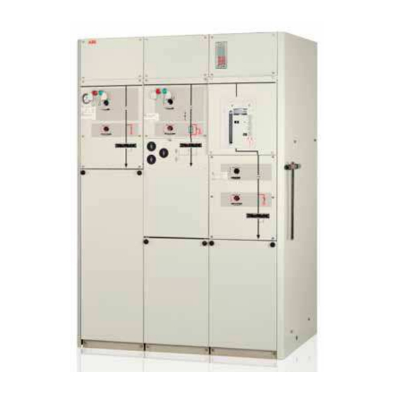
1. GENERAL DESCRIPTION SafeRing is a SF insulated ring main unit and SafePlus is a compact switchgear for applications in medium voltage distri- bution networks. SafeRing can be supplied as 2-, 3- or 4-way standard configurations with additional equipment according to customer specification. -
Page 4: Description Of Functions
1.1 DESCRIPTION OF FUNCTIONS Lifting lugs (hinged) Nameplate with serial number Mimic diagram Load break switch Earthing switch Switch-fuse disconnector Push buttons close/open Fuse canister Position indicator 10. Blown fuse indicator 11. Charged spring indicator 12. Padlock device 13. Cable compartment cover 14. -
Page 5: Dimensional Drawings
1.2 DIMENSIONAL DRAWINGS Unit 1-way 2-way 3-way 4-way A (mm) 1330 1750 1.3 SIDE CONNECTIONS REJ603 Installation and operating instruction | SafeRing/SafePlus 36kV 5... -
Page 6: Transport And Handling
Standard 2-way 600 kg ø30 SAFERING 36 3 and 4-way as for SafeRing The weights are including additional equipment. SafeRing / SafePlus is fitted with lifting lugs, but can also be moved on pallets with a forklift truck. -
Page 7: Technical Data
3. TECHNICAL DATA 3.1 ELECTRICAL DATA SafeRing / SafePlus 36 C-module F-module V-module Switch Earthing Switch-fuse Downstream Vacuum Earthing disconnector switch disconnector earthing circuit- switch/ switch breaker disconnetor Rated voltage 36/38,5/40,5 36/38,5/40,5 36/38,5/40,5 36/38,5/40,5 36/38,5/40,5 36/38,5/40,5 Power frequency withstand voltage 70/80/95 70/80/95 70/80/95... -
Page 8: Fuse Table
24,1 1YMB531006M0005 − Both tables above are based on using ABB CEF high-voltage current-limiting back-up fuse-links − Normal operating conditions with no overlaod of transformer (table 1) and with 20% overlaod of transformer (table 2) − Ambient air temperature -25... - Page 9 3.2 FUSE TABLE - SIBA SafeRing 36 Rated voltage: 36 kV Rated voltage: 40,5 kV SafePlus 36 Operating voltage: 30 kV Operating voltage: 35 kV F-panel at 36 kV: 840 A at 40,5 kV: 750 A transfer transfer 100% load...
-
Page 10: Installation
4. INSTALLATION When installing Ring Main Unit or Compact Switchgear The floor must be well leveled and the unit must be fixed by with Internal Arc Classification AFL, the following must be considered: means of anchor bolts in accordance with the dimensional −... -
Page 11: Cable Compartment
4.1CABLE COMPARTMENT NOTE! Removal of cable cover: The cable cover can be supplied with interlocking to earthing switches (additional equipment). When interlocking is fitted, the cable compartment can only be accessed when the earthing switch is in the closed position. 1. -
Page 12: Cable Connection
The following types are recommended: Euromold / Elastimold Tyco Electronics nkt-cables Prysmian Südkabel ABB Kabeldon Please see supplier documentation for details. The manufacturer’s installation instructions must be followed. Be sure to lubricate the bushings thoroughly with the silicone supplied. NOTE! -
Page 13: Relay And Current Transformers For Relay Protection
SafeRing / SafePlus with vacuum circuit-breakers are prepared for self-powered OCEF protection relay ABB type REJ 603. Relays with auxiliary voltage SafePlus can be delivered with advanced protection relays: −... -
Page 14: Gas Pressure
SF leakage from the SF tank pressure, please contact ABB for instructions (NHP 408025). 1. Remove the front cover and unscrew the pressure indicator by unscrewing the hexagon nut as shown on the figure at the right. 2. Screw the adapter to the valve. The tightening torque is max 45 Nm. -
Page 15: Operation
2500 meters, gas pressure has to be reduced according to figure on previous page. For installation above 2500 meters, please contact ABB for instructions. Special conditions In accordance with IEC 62271-1, the manufacturer and end- user must agree about special operating conditions which deviate from operation under normal conditions. -
Page 16: Operation
OPERATION Before any operation of mechanisms, make sure that front The vacuum circuit-breaker has an integrated lever for the covers are mounted. charging og the springs and push-buttons for operation. All switch-disconnectoer and earthing switches can be Internal mechanical interlocking between the switch- operated with the included operating handle. -
Page 17: Switch-Fuse Combination
5.2.3 SWITCH-FUSE COMBINATION Push buttons open and close switch-disconnector Uncharged Operating shaft, switch-disconnector Position indicator, Charged switch-disconnector Charged spring indicator Position indicator, earthing switch Operating shaft, 5.2.5 EARTHING SWITCH earthing switch Blown fuse indicator 5.2.4 SWITCH-DISCONNECTOR Earthing switch: Before entering handle, press interlocking bracket towards left. -
Page 18: Vacuum Circuit-Breaker, V-Module
5.2.6 VACUUM CIRCUIT-BREAKER - VCB Push button - VCB (OFF) Push button - VCB (ON) Indication - spring charged /( discharged VCB position indicator Counter - closing and opening operations Spring-charging leverr Before operating of the VCB, check that the spring is charged. -
Page 19: Installation And Replacement Of Fuse Links
5.3 INSTALLATION AND REPLACEMENT OF FUSE LINKS The F-module is equipped with a blown fuse indicator. If this indicator changes colour from white to red, this means that at least 1 fuse-link has blown. This will also automatically trip all three phases of the switch-fuse disconnector. - Page 20 5. If a fuse-link is already installed but has to be replaced, pull it out. 8. Press the handle and close the fuse canister. 6. Fix the new fuse-link to the fuse cover by means of the contact screw. Note! the striker pin must point towards the fuse cover.
-
Page 21: Additional Equipment
6. ADDITIONAL EQUIPMENT 6.1 MOTOR OPERATION AND AUXILIARY SWITCHES Circuit-breakers, switch-fuse disconnectors and load break switches can be equipped with motor operation. Available control voltages are 24, 48, 60, 110, 230 VDC and 110, 230 VAC. F- and V- modules can also be equipped with closing and opening coils. -
Page 22: Ronis Key Interlock
6.5 RONIS KEY INTERLOCK To prevent unintended operations, all switches (except switch-disconnector on switch-fuse combination and circuit- breakers) have the possibility to be equipped with Ronis key interlock type EL11AP. 6.6 PADLOCKING DEVICE Ronis key interlock Padlocking device All switches except circuit-breakers are equipped with pad- locking device as standard. -
Page 23: Environmental Certification
LIFECYCLE CONCEPT FOR TRANSPORT, INSTALLATION, REPAIR , SERVICE AND DISPOSAL AT END OF LIFE ABB is committed to the protection of the environment and It is ABB’s obligation to facilitate end-of-life recycling for our adhere to ISO 14001 standards. The unit contains no subs- products. - Page 24 For more information please contact: ABB AS Power Products Division P.O. Box 108, Sentrum N-3701 Skien, Norway Phone: +47 35 58 20 00 Fax: +47 35 52 41 08 www.abb.com...