Table of Contents
Advertisement
Advertisement
Table of Contents

Related Manuals for ABB SV/S 30.160.1.1


Summary of Contents for ABB SV/S 30.160.1.1
- Page 1 — PRODUCT MANUAL ABB i-bus® KNX SV/S KNX-Power Supplies...
-
Page 3: Table Of Contents
® ABB i-bus Contents side Contents General ....................3 Using the product manual ......................3 1.1.1 Structure of the product manual ....................4 1.1.2 Notes ............................4 Product and functional overview ....................5 1.2.1 Brief overview ..........................5 Device technology ................7 Standard Power Supply, 640/320/160 mA, MDRC ...............7 2.1.1... -
Page 5: General
® ABB i-bus General General KNX power supplies provide the system voltage (SELV) for KNX components. The choked output voltage powers individual components and enables them to communicate. Using the product manual This manual provides detailed technical information about the power supplies and how to mount and program them. -
Page 6: Structure Of The Product Manual
® ABB i-bus General 1.1.1 Structure of the product manual All parameters are initially described in chapter 3. Following the parameter descriptions are descriptions for the communication objects. Please note The descriptions of parameters and communication objects in section 3 apply only to those power supplies with diagnostics functions (SV/S 30.320.2.1 and SV/S 30.640.5.1). -
Page 7: Product And Functional Overview
ABB i-bus General Product and functional overview ABB power supplies are designed to be fully compatible with each other. Devices with diagnostics or bus functions for complex applications are available alongside standard devices. An uninterruptable battery backed-up version is also available. -
Page 9: Device Technology
Technical data 100 – 240 V AC, 50/60 Hz Supply Supply voltage U (85…265 V AC) Power consumption Normal operation Maximum - SV/S 30.160.1.1 6.6 W 21 W - SV/S 30.320.1.1 12.5 W 30 W - SV/S 30.640.3.1 24 W... - Page 10 ® ABB i-bus Device technology Protection class EN 61 140 Isolation category Overvoltage category III under EN 60 664-1 Pollution degree 2 under EN 60 664-1 Temperature range Operation -5 °C…+45 °C Storage -25…+55 °C Transport -25…+70 °C 93 %, no condensation allowed...
-
Page 11: Connection Schematic
® ABB i-bus Device technology 2.1.2 Connection schematic Bus connection terminal Label carrier Power supply connection U Status LED Voltage output without choke, I (SV/S 30.640.3.1 only) SV/S xx.xxx.x.1 | 2CDC501049D0201 Rev. A 9... -
Page 12: Dimension Drawing
® ABB i-bus Device technology 2.1.3 Dimension drawing 10 2CDC501049D0201 Rev. A | SV/S xx.xxx.x.1... -
Page 13: Operating And Display Elements
® ABB i-bus Device technology 2.1.4 Operating and display elements Indicator Description Function LED status Two-colored indicator for displaying mains Green: Device operating normally (I < I (green/red) voltage, overload and short-circuit. For Red: Overload (I < I < I SV/S 30.640.3.1, overload and short-circuit... -
Page 14: Knx Power Supply With Diagnostics, 640/320 Ma, Mdrc
® ABB i-bus Device technology KNX Power Supply with diagnostics, 640/320 mA, MDRC KNX power supplies generate and The LEDs indicate the bus current monitor the KNX system voltage (SELV). consumption and the status of the line or The bus line is decoupled from the power device. - Page 15 ® ABB i-bus Device technology Operating and display elements Programming button and LED (red) For assignment of the physical address OK LED (green) ON: Bus voltage and mains voltage OK LED I > I (red) ON: Short-circuit or overload Bus current LEDs (7 x yellow) ON: Indicates present bus current Telegr.
- Page 16 Please note ETS and the current version of the device application are required for programming. The current version of the application is available for download at www.abb.com/knx. After import it is available in ETS under ABB/System devices/Power Supplies. The device does not support the password function of the KNX device in ETS. If you inhibit access to all the project devices using a BCU code, it has no effect on this device.
-
Page 17: Connection Schematic
® ABB i-bus Device technology 2.2.2 Connection schematic Bus connection terminal Programming button and LED (red) Label carrier Reset button and LED (red) Comm. error LED (yellow) Telegr. LED (yellow) Power supply connection U OK LED (green) I > I... -
Page 18: Dimension Drawing
® ABB i-bus Device technology 2.2.3 Dimension drawing 16 2CDC501049D0201 Rev. A | SV/S xx.xxx.x.1... -
Page 19: Operating And Display Elements
® ABB i-bus Device technology 2.2.4 Operating and display elements Operation/ Description Function Indicator light LED green Indicates status of mains and output Mains voltage present, device operating normally voltage (I < I The LED is off during programming. OFF:... -
Page 20: Mounting And Installation
VDE 0100-520. Commissioning requirements ® To commission the device you will need a PC with ETS, a connection to the ABB i-bus e.g. via a KNX interface, and a supply voltage of 110/230 V. Mounting Mounting and commissioning may only be carried out by electrical specialists. -
Page 21: Start-Up
The devices are parameterized using the application program and Engineering Tool Software (ETS). The application program can be found at ABB/System devices/Power Supplies. For parameterization purposes, a PC or Laptop with ETS and a connection to the KNX, e.g. USB or IP interface, is required. -
Page 22: Conversion Of Previous Application Program Versions
Start-up Conversion of previous application program versions ® For ABB i-bus KNX devices, it is possible to adopt the parameter settings and group addresses from earlier versions of the application program from ETS3. At the time of the market launch of the SV/S 30.640.5.1 and SV/S 30.320.2.1 power supplies there is no previous version of the application program. -
Page 23: Parameters
ETS is required for this programming. The application program is available in ETS under ABB/System devices/Power Supplies. The following section describes the parameters of the application program. Parameter windows are structured dynamically so that further parameters may be enabled depending on the settings and the function. -
Page 24: Parameter Window General
® ABB i-bus Start-up 3.3.1 Parameter window General Send communication object "In operation" Options: send value 0 cyclically send value 1 cyclically The communication object In operation indicates the presence of the device on the bus. This cyclic telegram can be monitored by an external device. If a telegram is not received, the device may be defective or the bus cable to the transmitting device may be interrupted. - Page 25 ® ABB i-bus Start-up Send status values Options: no, update only after a change after request after a change or request These parameters determine the send behavior of the status values. Status values are: Total current I > Rated current I (SV/S 30.640.5.1 only)
-
Page 26: Communication Objects
® ABB i-bus Start-up Communication objects 3.4.1 Summary of communication objects Flags Data Point Function Name Length Type (DPT) General In Operation DPT 1.002 1 bit Request status/measured values General DPT 1.017 1 bit Measured value Bus voltage U DPT 14.027... -
Page 27: Communication Objects, General
® ABB i-bus Start-up 3.4.2 Communication objects, General Function Communication object name Data type Flags In Operation General 1 bit C, R, T DPT 1.002 The communication object is enabled if send value 0/1 cyclically is selected for the parameter Send communication object "In operation"... - Page 28 ® ABB i-bus Start-up Overload I > I Status value 1 Bit C, R, T DPT 1.005 The device uses this communication object to report that an overload has been detected on the output. If an overload is detected for > 10 seconds then a telegram with the value 1 is sent. The object value 0 is sent as soon as the current falls...
-
Page 29: Planning And Application
® ABB i-bus Planning and application Planning and application Additional voltage output Type SV/S 30.640.5.1 and SV/S 30.640.3.1 devices have a 30 V DC voltage output without choke. This can be used in combination with an additional choke to power a main or area line. To do this, the devices must be installed in accordance with the connection schematic below. -
Page 30: Reset
® ABB i-bus Planning and application Reset During a reset the bus line is disconnected from the output voltage and shorted. This restarts devices connected to this bus line. The red Reset LED lights up for the duration of the reset. The LED goes off when the reset is complete. -
Page 31: Faults
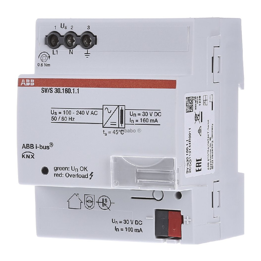
® ABB i-bus Planning and application Faults SV/S 30.640.3.1, SV/S 30.320.1.1 and SV/S 30.160.1.1 Indicators for normal operation, short-circuit and overload Description Recommendation green/ Device operating normally. green Output overloaded. Rectify overload or reduce number of bus devices until there is no longer an overload and only the green U OK LED is lit. -
Page 33: A Appendix
Short description Description Order No. bbn 40 16779 Price Weight group 1 pcs [kg] [pcs.] SV/S 30.160.1.1 KNX Power Supply, 160 mA, MDRC 2CDG110144R0011 86666 8 0.25 SV/S 30.320.1.1 KNX Power Supply, 320 mA, MDRC 2CDG110166R0011 90619 7 0.25 SV/S 30.640.3.1... - Page 34 ® ABB i-bus Appendix Notes 32 2CDC501049D0201 Rev. A | SV/S xx.xxx.x.1...
- Page 36 With regard to purchase or- ders, the agreed particulars shall prevail. ABB AG does not accept any responsibility whatsoever for potential errors or pos- sible lack of information in this document. We reserve all rights in this document and in the subject matter and illustrations con- tained therein.